Hilton Audio MA-150 User manual

HILTON MA-150
SOUND SYSTEM
OPERATING INSTRUCTIONS
Please read this manual carefully, and keep it in a safe place for future reference. It contains valuable
information about your new Hilton MA-150 sound system: its features, how to operate it, how to take
care of it, how to avoid damage to it, what to do if any problems should occur.
If you should encounter any problem in setting up or in operating your Hilton sound system, or if you
have any question which is not answered in this manual, please write or phone.

HILTON AUDIO PRODUCTS of TEXAS, LLC.
9727 SUGAR TREE COURT –HOUSTON, TX - 77070
PHONE (713) 955-5911 FAX (713) 429-5026
e-mail: info@hiltonaudio.com web site: www.hiltonaudio.com

TABLE OF CONTENTS
GUARANTEE OF SATISFACTION......................................................................................................... Page 1
TOP DECK PANEL ...............................................................................................................................Page 3
FRONT EDGE PANEL...........................................................................................................................Page 3
REAR PANEL........................................................................................................................................Page 4
CONNECTING THE SIGNAL SOURCE ................................................................................................. Page 5
SETUP AND OPERATION.....................................................................................................................Page 6
SPEAKER HOOKUP..............................................................................................................................Page 6
GETTING THE MOST FROM YOUR HILTON .......................................................................................Page 8
MAKING RECORDINGS ........................................................................................................................Page 9
CONNECTING TO AN EXTERNAL AMPLIFIER................................................................................... Page 10
ROUTINE INSPECTION AND MAINTENANCE .................................................................................... Page 10
IN CASE OF TROUBLE .......................................................................................................................Page 11
MULTIPLE SPEAKER HOOKUP DIAGRAMS....................................................................................... Page 13
SCHEMATIC - PREAMP ..................................................................................................................... Page 14
SCHEMATIC - POWER AMPLIFIER.................................................................................................... Page 15
SCHEMATIC - POWER SUPPLY ........................................................................................................ Page 16

1
GUARANTEE OF SATISFACTION
Any purchaser of Hilton sound equipment, if not completely satisfied with it, may return such equipment in
undamaged condition, freight charges prepaid, within 30 days after original purchase, for full refund of its purchase
price.
TWO-YEAR LIMITED WARRANTY
For a period of two years after initial purchase, Hilton Audio Products will, at its option, either repair or replace
without charge any Hilton sound system or component thereof which fails in normal service, subject to the
exceptions listed below. Any reasonable shipping and transit insurance charges, within the continental U.S.A.,
incurred in the course of warranty service will be paid by Hilton Audio Products.
EXCEPTIONS TO WARRANTY:
Warranty is restricted to correction of any defect which becomes evident in the course of normal use and operation,
and does not cover any of the following:
1. Repair of normal wear and tear: scratches, nicks, dents, etc.
2. Modernization or alteration to specifications which were not in effect at the time of original purchase.
3. Repair of damage which is caused by accident or abuse and not by any defect in the sound system.
4. Reimbursement for any repair charges not authorized by Hilton Audio Products.
5. Repair of damage which is caused by connecting the sound system to any portable generator or inverter.
6. Repair of damage which is caused by using any other connection or hookup which is stated in this manual
to be improper and likely to cause damage to the sound system.
7. Replacement of any unit which has been modified or altered in any way, by adding inputs or outputs, by
permanently changing its appearance by painting, engraving in an exposed spot, etc.

2
8. Payments of any transit charges, freight, insurance, customs charges or brokerage fees, which may be incurred
in providing warranty service involving international customers. Any such charges, if advanced by Hilton Audio
Products, will be invoiced to the owner of the equipment.
9. Hilton Audio Products assumes no responsibility for any special, incidental or consequential damage.

3
HILTON MODEL MA-150
Sound System

4
TOP DECK PANEL
MON. SECTION:
The MON. OUT jack signal level and mode is controlled in this section. The slide switch will select either the VOICE
or the MUSIC program to be monitored. The signal out is adjusted with the LEVEL control.
MUSIC SECTION:
The MUSIC volume control adjusts the loudness of the music program when playing a Laptop Computer, MP3,
CD or other signal through the two AUXILIARY inputs. Adjustment of music volume can also be done by using
the Hilton remote volume control assembly in conjunction with the volume control.
MUSIC BASS AND TREBLE CONTROLS: Adjust the bass and treble compensation for the music program. They
have no effect on any of the voice program channels. Very wide latitude is provided, and we recommend using
only the minimum adjustment from normal which will give you the music sound that you desire. See also the section
titled GETTING THE MOST FROM YOUR HILTON.
MICROPHONE SECTIONS:
Four high impedance microphone inputs are provided. Volume and tone controls are completely independent of
each other, and of the music program.
MICROPHONE TONE CONTROLS: One of the features which makes the Hilton sound systems outstanding is
the ability of their voice circuits to reproduce cleanly the high frequencies which are absolutely essential for voice
clarity. If you have a voice in the bass range, turn the tone control to the right far enough to be sure that there
is no boomingness; if you are a baritone, leave it near the normal setting.
AUX 1/AUX 2 INPUTS:
These four controls are used to feed signals into the MUSIC section of the MA-150's preamp. Examples of signal
input sources would be Laptops, MP3, CDs, Mini-Discs or Turntables. The controls marked BALANCE and
LEVEL are input controls. These four controls are fed by the 3.5mm stereo jacks marked AUX 1 and AUX 2
on the Front Edge of the MA-150. The BALANCE adjusts the signal level between A & B of a two track or stereo
signal. The LEVEL control sets the volume feeding the MUSIC section.
POWER:

5
This red light comes on as soon as the AC power switch is turned ON.
AUXILIARY AC OUTLETS:
Two, three prong switched auxiliary AC sockets are provided. These outlets are switched off/on by the power
switch in the POWER ENTRY MODULE. These are meant to be used for low wattage external devices such
as: a wireless microphone, tape recorder, or CD player. Do not exceed 60 Watts combined. The circuit does go
through the main fuse in the POWER ENTRY MODULE. The voltage will be the same as the supplied line
voltage.
FRONT EDGE PANEL
MON. OUT:
A gold RCA phono jack is provided for connecting to an external amplifier for monitoring either the voice or the
music program. This output may also be used to connect an Assistive Listening System, a recorder, amplified
speaker, or other system. The output level is adjustable.
AUX 1 & AUX 2:
Two 3.5mm stereo jacks are provided for feeding signals into the MUSIC section of the MA-150.
Jacks AUX 1 and AUX 2 are used to feed signals into the system. The Top Panel controls marked BALANCE
and LEVEL adjust the signal from these two jacks before the signal reaches the MUSIC section. Left and Right
stereo signals can be connected directly to the two jacks or two separate signal sources can be connected.
Examples of using these two jacks are: The left and right channel of a CD to AUX 1 and a MP3 player into AUX
2. See the section PLAYING LAPTOPS, MP3's, CD's, & ?, for more details on using these jacks.
REMOTE CONTROL JACK:
By plugging in the Hilton remote volume control assembly into MUSIC REMOTE, the music volume can be adjusted
with the knob at the microphone, without touching the knob on the top panel.
Recommended operation: Plug in the remote control cord and turn its volume full on. Set the MUSIC volume
control at a level slightly higher than you need for best voice-music balance. With the remote control, decrease
the music level so that your voice comes out clearly over the music. Without touching the amplifier knob you
can now adjust the music volume from the remote cord.
The remote will not turn the music totally off. If you do not want any music, use the MUSIC VOLUME control.
MIC 1, 2, 3, & 4:

6
Four high impedance microphone inputs are provided.
REAR PANEL
SPEAKER OUTPUT JACKS:
Two speaker jacks are located on the rear of the MA-150.
The speaker outputs are mono 1/4" phone jacks, compatible with standard mono 1/4" phone plugs. The jacks
are connected in parallel with each other. Optimum impedance load is 4 to 16 ohms. Do not connect any
combination of speakers which produces a net impedance load of less than 4 ohms. One series Y connector
is furnished with the MA-150, for use in connecting more than two speakers. See the section titled SPEAKER
HOOKUP for detailed instructions for hookup of multiple speakers.
Do not connect a tape recorder or any other sound equipment to the speaker jacks of the MA-150. Doing so
could cause overheating of the amplifier, and possibly damage it.
SIGNAL OUT:
Two gold RCA jacks are provided, one marked HIGH and the other LOW. Both jacks will vary in volume with the
setting of the MUSIC and MIC volume and the tone controls.
The HIGH jack is a variable line level signal (sometimes referred to as an auxiliary level). It is used to feed a
line level signal to an exterior system.
The LOW jack is a variable microphone level signal. It is used to feed a microphone level signal to an exterior
system.
These two jacks may be used for making monaural recordings from the MA-150, or to connect a slave amplifier
to gain even more power and coverage. When using these outputs remember they are dependent on the volume
and tone setting of the MUSIC and MIC controls.
See the sections titled MAKING RECORDINGS and CONNECTING TO AN EXTERNAL AMPLIFIER.
POWER ENTRY MODULE:
The power entry module contains the power off/on switch, fuse holder, voltage selector and power cord
receptacle.
7
Units which have been damaged by connecting to a wrong power source will not be covered by the warranty.
To open the power entry module to replace the fuse or change voltage, use a small screwdriver or similar device.
Remove the power cord, insert the tip of the tool at a 45 degree angle into one of the notchs between the power
cord receptacle and the power module cover, and apply pressure towards the cover while prying outward.
To change the fuse: remove the fuse holder that is located under the cover and the fuse is easily removed and
replaced. Recommended fuses for 100V or 120V operation: one MDQ3, (3 amp, 250V), for 230V or 240V
operation; two GDC1.6, (1.6 amp, 250V), one for each power leg. Unplug the aux input before turning the unit
on again. If the fuse again blows almost
immediately, unplug the amplifier and
do not attempt to use it until the cause of
the problem has been determined.
Refer to the trouble shooting section of this
manual.
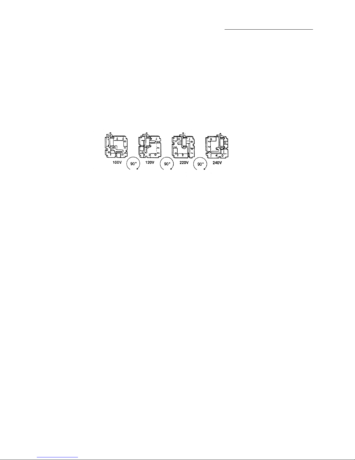
To Change Selected Voltage: Four AC voltages can be used with the MA-150: 100V, 120V, 230V or 240V.
To change between voltages, pull the voltage selector card straight out of the housing using the indicator pin.
Orient the selector card so that the desired voltage is readable at the bottom of the card. Orient the indicator
pin to point up when the desired voltage is readable at the bottom. Insert the voltage selector card into the housing
with the edge showing the selected voltage entering first and the printed side of card facing the fuse compartment.
Reinstall the cover and verify the indicator pin shows the desired voltage.
Voltage Selector Card Orientation
If required, the fuse holder may be changed to take either a single North American fuse or two European standard
fuses. To change, open the power entry module door and remove the fuse holder, insert the correct fuses, turn
the holder over and reinstall. You will not see the fuses when the fuse holder is correctly installed in the power
entry module. The European arrangement requires two fuses. Older model MA-150's require a Phillips screw driver

8
to change the fuse type from European to North American type fuses.
The MA-150 is further protected by an internal thermal circuit breaker. In the event of too much heat build-up,
the thermal circuit breaker will turn the MA-150 off. Once the heat has dissipated, the thermal circuit breaker will
automatically reset itself. Turn the power switch off, and before restarting, check for the cause of the overheating.
Improper speaker hook-up resulting in a low (under 4 ohms) speaker impedance is the most likely cause of
overheating. A shorted speaker cord or Y connector are other possible causes.
CONNECTING THE SIGNAL SOURCE
AND PLAYING BACK LAPTOPS, MP3's, CD's, & ?
Why, you may ask, the ?in the above title? New products are coming out all the time in the audio industry. It
is likely that other new systems are on the drawing boards or in the minds of engineers that we could not even
guess at. Because of this, the MA-150 was designed with enough flexibility that all current, as well as future,
designs will work with your MA-150!
We can make the last statement with confidence because of the design flexibility of the playback circuit in the
MA-150. That being said, we must also point out that having this amount of flexibility requires a greater
understanding of how to use it on your, the owner's, part.
CAUTION: Do not use the microphone inputs for tape playback.
HUM OR BUZZ WHEN USING YOUR LAPTOP? —SEE PAGE 12 FOR THE EASY FIX.
First let's go over some general rules for playing back through the MA-150. Later in this section we will get into
specifics on connecting particular types of devices to the MA-150.
SETTING THE CONTROLS:
Use caution in setting the INPUT LEVEL control and output volume from your signal source. Setting either
too high can result in distortion, especially during peaks in the music program. Keep in mind that you are
using the INPUT LEVEL controls and output control on the signal source to set the proper signal level going
into the MA-150, not as volume controls. Once these are set, then use the MUSIC control to adjust the

9
volume.
Before connecting the Laptop, MP3, CD, or ?, do the following to the MA-150. Set the music volume control
at or below nine o'clock and the music bass and treble controls at normal. Set the BALANCE and the LEVEL
controls at midway position. Connect the signal source as described below. With CDs and Mini-Disc players use
the line out jack. Once connected, turn up only enough volume on the recorder or other signal source to get a
soft listening level. If your unit has an auxiliary out jack, this may also be used, but the signal has a fixed level
from the source. Now adjust the music bass and treble controls to get the sound quality that you want.
PLAYING BACK MONAURAL MP3, CD, MINI-DISC, TURNTABLE OR OTHER SIGNAL SOURCE:
Connect a shielded cord from the output of the recorder or other signal source to either the AUX 1 or AUX 2 jacks
on the Front Edge Panel. Set the controls as described above.
PLAYING BACK STEREO MP3, CD, MINI-DISC, TURNTABLE OR OTHER SIGNAL SOURCE:
Connect a shielded stereo cord from the output of the recorder or other stereo signal source to AUX 1 or AUX
2 jacks on the front edge panel. Set the controls as described above.
SETUP AND OPERATION
Set the unit on a smooth flat surface, advoid carpeting or any sufrace that may block the air vent slots on the
bottom of the unit. Clearance under the unit is required to allow sufficient air flow for cooling.
Turn all the volume controls off, the power switch off, and set the tone controls at normal. Connect and turn on
the music source. Set up your speaker or speakers. Connect them to the amplifier, following the instructions given
in the section titled SPEAKER HOOKUP. Plug in your microphone.
Check to be sure that the power source is the correct voltage. Plug in the power cord, and turn the system on.
Turn on the microphone and test by speaking into it--not by blowing into it. Adjust the music volume and tone
controls. In a unfamiliar area, walk the floor to make sure that your speakers are properly located to cover the
entire area with a comfortable level of sound.
SPEAKER HOOKUP
The minimum impedance load for the MA-150 is 4 ohms.

10
Depending upon the size, shape, and acoustic characteristics of a hall, getting comfortable sound coverage may
require one, two or more speakers. It is important to locate them properly, for best coverage of all areas of the
floor. For information on locating speakers in the hall, see the heading SPEAKER LOCATION in the section titled
GETTING THE MOST FROM YOUR HILTON.
It is also very important to connect them properly, to the amplifier and to each other, to get the best performance
from the amplifier and from the speakers.
In a multiple speaker hookup, it is necessary to consider impedance. This is the electrical resistance of the voice
coils of the speakers. The lower the impedance, the more electrical energy is applied to the speakers. This is
why specifications on power amplifiers will show a given power rating into an 8-ohm load, and a higher power
output into a 4-ohm load.
If a loudspeaker were 100% efficient, all of the electrical energy delivered to it by the amplifier would be converted
into sound energy. Unfortunately, speakers are not 100% efficient; in fact even the highest quality speakers in
the best designed enclosures are no more than 25% efficient. The electrical energy which is not converted to
sound by a speaker is converted into another form of energy--heat. This heat must be dissipated at two points:
the voice coil of the speaker, and at the amplifier. Excessive heat at either point can cause damage to the sound
system.
Improper hookup can cause excessive heat dissipation, and this problem is compounded when less efficient
speakers are used.
By carefully following the instructions in this manual for speaker hookup, you will maintain the best net impedance
load for various speaker combinations. Improper hookup of speakers can cause embarrassing interruptions of
your program, even if you are using Hilton speakers. Over-driving speakers with low power ratings or connecting
them improperly can cause damage to the speakers, and in the event of a shorted voice coil, possibly cause
damage to your amplifier.
ONE HILTON PS-10 OR LB-1 SPEAKER
Plug directly into one of the speaker jacks. Impedance: 4 ohms.
ONE HILTON WORKSHOPPER OR FOLDED HORN SPEAKER (FH-10 OR FH-12)
Plug directly into one of the speaker jacks. Impedance: 8 ohms.
TWO HILTON PS-10 OR LB-1 SPEAKERS
Plug each speaker into a series Y, then plug the Y into one of the speaker jacks. Impedance: 8 ohms.

11
TWO HILTON WORKSHOPPER OR FOLDED HORN SPEAKERS (FH-10 OR FH-12)
Either plug both speakers into the amplifier or plug one speaker into the amplifier and connect the second speaker
to the first speaker. Impedance: 4 ohms, either way.
MORE THAN TWO SPEAKERS
DO NOT CONNECT MORE THAN TWO 8 OHM SPEAKERS OR MORE THAN ONE 4 OHM SPEAKER TO THE
MA-150 WITHOUT CAREFULLY READING THE INSTRUCTIONS WHICH FOLLOW, AND THE DIAGRAMS
CONTAINED IN THIS MANUAL.
HOW TO DETERMINE NET IMPEDANCE
To determine the net impedance of a given combination of speakers, it is necessary to understand and apply the
following:
IMPEDANCE: The resistance produced by the voice coil of a speaker, expressed in ohms. Hilton Folded Horn
and Workshopper speakers are 8 ohms, the PS-10 and LB-1 are 4 ohms; other makes have varying impedances,
usually from 4 to 16 ohms.
PARALLEL CONNECTION: A hookup in which the output of the amplifier is divided among speakers, with part
of the output going to each speaker. The speaker jacks are connected in parallel. The jacks on top of the Hilton
Folded Horn speaker are also connected in parallel with each other.
SERIES CONNECTION: A hookup in which all of the amplifier output passes through each speaker in turn,
instead of being divided up among them. If you plug a series Y connector into the amplifier and connect one
speaker to each leg, you have the speakers connected in series.
SERIES-PARALLEL CONNECTION: If you have two groups of speakers which are connected in parallel within
the group, and connect one group to each leg of a series Y connector, you have a series-parallel connection.
NET IMPEDANCE--The combined impedance of all speakers in a hookup:
(Each speaker must be the same impedance)
IN PARALLEL--the impedance of 1 speaker, divided by the number of speakers in the parallel hookup.
IN SERIES--the impedance of 1 speaker, multiplied by the number of speakers in the series hookup.
IN SERIES-PARALLEL--the net impedance of each parallel group, multiplied by the number of parallel
groups connected in series.

12
The minimum impedance load for the MA-150 amplifier is 4 ohms, for best operating results. Hilton Workshopper
and Folded Horn speakers are 8 ohms and the LB-1, WA-180, and PS-10 are 4 ohms. Two 8 ohm speakers
connected direct to the MA-150 produces a 4-ohm load. If you should connect four 8 ohm speaker in parallel
or two 4 ohm speakers directly to the MA-150, this parallel connection produces a 2 ohm load, which at high
drive levels will produce excessive energy which is dissipated in the form of heat and cause the MA-150 to shut
down.
The hookup diagrams in this manual show correct use of the series Y connectors for hookup of 4, 6, and 8
speakers, to obtain equal volume level from each speaker and maintain proper net impedance. If it should be
necessary to connect 5 or 7 speakers, a slave amplifier should be used. It is impossible to get equal volume
from these combinations with a single amplifier.
If you must use a speaker hookup not shown in these diagrams, or if you plan multiple hookup of speakers not
manufactured by Hilton, the following points must be considered:
1.You must use a hookup which will produce a net impedance load of 4 ohms or higher.
2.The net impedance to each leg of a series Y connector should be the same, or the speakers driven by one
leg will receive more energy and therefore produce more volume than those driven by the other leg.
3.Different makes and types of speakers have different degrees of efficiency and will produce different sound
volumes when driven at the same amplifier output level. Mixing different types of speakers is not recommended,
but if you must do so, use the more efficient speakers nearest the center to cover the main portion of the floor,
and the less efficient ones at the ends to cover the two front corners of the floor.
CONNECTING SPEAKERS OTHER THAN HILTON SPEAKERS
Any one speaker with the impedance of 4 ohms or higher can be connected directly to the MA-150.
Before connecting two speakers, first find out their impedance. If they are 8 ohms or higher, use the same hookups
as for the Hilton Workshopper or Folded Horn speakers. Two 4-ohm speakers must be connected in series, use
the hook-up for two Hilton PS-10 or LB-1. For other combinations, follow the instructions given above to obtain
a net impedance of no less than 4 ohms.
CHECK THE POWER RATING OF THE SPEAKER AND BE CAREFUL NOT TO EXCEED IT. Over-driving of
a speaker with a low power rating can result in any of the following: 1. Distortion of the program. 2. The voice

13
coil may become jammed at one end of its excursion, making the speaker inoperative. 3. A short circuit may
occur in the voice coil, ruining the speaker and possibly causing damage to your amplifier.
NEVER CONNECT TWO AMPLIFIERS TO THE SAME SPEAKER OR SPEAKERS!
GETTING THE MOST FROM YOUR HILTON, AND AVOIDING DAMAGE TO IT
MICROPHONE TECHNIQUE
Always work close to your microphone -- never let it get more than an inch from your lips. Work straight into
it, as much as possible. Holding the microphone too far from your lips, or speaking across it rather than into
it, can rob you of more than half the power and efficiency which is built into your Hilton. If you hold your
microphone two inches from your lips, it won't pick up half as much sound as at one inch--it will pick only one-fourth
as much. If you then try to turn up four times as much gain in an attempt to be heard, you will be fighting feedback.
FEEDBACK
The feedback squeal can occur at any time that power is turned up on an amplifier and an open microphone is
near a loudspeaker. The more power is turned up, or the closer the microphone is to the speaker, the more likely
feedback will occur. The squeal is caused by sound from the speaker being picked up by the microphone and
fed back into the amplifier. It is almost always the result of bad microphone technique, working so far from the
microphone that you have to turn up an excess of power in order to cover the floor. It can also be caused by
standing too close to a speaker. Only very rarely is feedback caused by any defect in the sound system.
SPEAKER LOCATION
Speakers should be placed so that the entire area is covered with sound. You should set up so that you can get
close enough to a speaker to be able to hear the voice-music balance, but not so close that you are continually
fighting feedback. Try never to aim a speaker directly at a hard, flat, painted or panelled wall, which will cause
echo and bounce-back of sound. If you must direct speakers towards such a surface, tilt them downward.
Wherever it is practicable, direct speakers towards an absorbent surface--one which is draped or acoustically
treated.
USING YOUR TONE CONTROLS
In a hall which is excellent acoustically, you can set your tone controls, within limits, almost any way you choose,

14
to get the sound quality of voice and music that you prefer.
But in a hall which is reverberant, not only must the voice-music balance be adjusted to compensate for the acoustic
conditions, but the tone controls for both music and voice must also be adjusted. In a reverberant hall, not only
must you cut the music volume down, but you should also use your tone controls to remove excess bass boominess
from the music, and take out some of the highs in the music.
REVERBERATION TIME
To determine the reverberation time of a hall, stand in the center of the empty hall, clap your hands, and carefully
count the number of seconds before the sound dies away completely. 1 second or less: excellent acoustic
conditions. 2 to 2-1/2 seconds: not good, but with speakers placed properly and careful attention to voice-music
balance and tone compensation, it is possible to get fairly good sound, with good intelligibility. 3 seconds or more:
the sound will not be good, no matter what equipment you use or how well you operate it. Only acoustic treatment
of such a hall will help produce better sound.
HANDLING AND TRANSPORTING
Your Hilton is designed for ruggedness, and with the normal handling to be expected in portable use, it will give
you years of trouble-free service. You may stow components in any position for transporting, as long as they are
protected from being excessively bumped or banged around.
MAKING RECORDINGS
There are many types and brands of recorders on the market, ranging from very compact and inexpensive, up
to premium quality models with quite sophisticated features. Even within the same price range, one model may
have different characteristics from another, and the same hookup which produces good results with one recorder
may not do so with another. Therefore, it may require a bit of experimenting to arrive at the hookup and
adjustments which give the best results with a given recorder.
CAUTION
Do not allow anyone to connect a recorder directly to the speaker socket, to the series Y connector, or to any
socket on a speaker. Some recorders have inputs of such low impedance that if they are connected in a speaker
circuit they produce the same effect as an improper speaker hookup: overheating and possible damage to the
MA-150.
MONAURAL RECORDINGS

15
Use the SIGNAL OUT jacks on the Rear Panel to make Monaural recordings with full program (the same as is
going to the speaker). The HIGH jack is an adjustable line level signal and would be connected to the Line or
Auxiliary input of your recorder. The LOW jack is an adjustable microphone level signal and would be connected
to the Microphone input of your recorder. The signal strength at these two jacks is dependent on where the MUSIC
and MIC volume (and tone) controls are set. If you have a choice of using either one with your recorder we suggest
you make short test recordings both ways to find which one works best with your recorder.
If you have a recorder that has an automatic recording level control (ARL or ALC) and you use this feature, it
will record with a wide range of input signal strength. But during pauses with no signal, there may be annoying
hash or background noise. Some of these units also have a manual adjustment for recording level, therefore we
recommend using the manual control to avoid this noise problem.
Another way to make monaural recordings is by the use of a telephone pickup (also referred to as "inductive
pickup's"). These are available at many outlets--Radio Shack, for instance. To use one of these pickups, loop
your speaker cord around it and secure it snugly with a rubber band. Plug the other end of the cord into the
microphone input on the recorder. With some recorders, this produces better results than a direct hookup. No
matter what recorder is used, no damage can be caused because there is no direct contact with your sound system;
the pickup is made through the insulation on the speaker cord. One other advantage is multiple recorders can
be connected. The speaker cord must be connected to a speaker, or no signal will be produced.
CONNECTING TO AN EXTERNAL AMPLIFIER
The gold RCA jacks, OUTPUTS - LOW and HIGH, on the Rear Panel can be used for feeding a signal to an
external amplifier or a "House" sound system. The LOW output is used to connect into a high impedance
microphone input of another amplifier. Use the HIGH output to connect into an auxiliary input or LOW to a Mic.
input.
If the slave amplifier must be located more than 30 feet away from the main amplifier, the use of a plain shielded
high impedance cable is not recommended, because of the noise that will be introduced into the system. In this
case, you must use sufficient length of LOW IMPEDANCE cable, and a pair of LINE MATCHING
TRANSFORMERS.
Disconnecting a slave hookup: Before disconnecting, make sure that both the main and the slave amplifiers are
turned off. If they are turned on and volume controls are turned up, unplugging will cause a loud pop in the
speakers, and even possibly damage them.

16
ROUTINE INSPECTION AND MAINTENANCE
Routine cleaning and inspection of your sound system, microphone and cords will help in preventing trouble and
maintain the appearance and performance of your Hilton.
POWDER COATED AND FINISHED SURFACES
Clean all of the powder coated and finished surfaces and knobs with a soft cloth or sponge dampened with a
mild detergent solution. Do not use harsh chemical cleaners or solvents as they may damage the surface. A
vacuum cleaner with a duster brush attachment does a good job cleaning dust and loose dirt on the amplifier.
CHECKING OF PLUGS, SOCKETS, AND CORDS
Cords, plugs, and sockets take more punishment than any other component of your sound system. For this
reason, they should get extra attention, more frequent checkups, and extra care in handling and stowing to prevent
failure in operation. Fortunately, there are advance warning signals before these components fail. If you know
what to look for, you can avoid embarrassing failures.
To check your cords, set up your sound system and plug in your mic. Wiggle each plug in its socket and flex
each cord along its length; do this for all mic and speaker cords. Listen for static and interruptions, which are
warning signals of future trouble.
CHECKING THE MICROPHONE
Check your microphone from time to time -- has its response changed? A mic whose diaphragm is starting to
drag will lose its bass response and sound tinny, and there will be an increased susceptibility to feedback. Care
of a microphone is fairly simple. Don't drop it, don't blow into it and don't spray or squirt anything into it in an
attempt to clean it. Keep your microphone in a dry place when not in use. Excessive moisture inside the
microphone can cause corrosion and oxidation resulting in unnatural sound or a complete microphone failure.
While checking your microphone look for any screws that might have loosened on the mic itself or on the remote
cord assembly. Carefully tighten any loose screws or nuts, and replace any that are missing. Examine the
microphone cable especially where the wires enter the plugs -- look for frayed or bare wires and loose connections.
With the microphone plugged into the amplifier and turned on, speak into the mic while moving the cable. Listen
for crackling noises or intermittent operation indicating broken or loose wire/s. Microphone cables are constructed
with shielded cable and like any wire will withstand only so many twists and bends before the wires will break.
When storing your mic cord, coil the cord avoiding sharp bends -- this will certainly extend the life of your

17
microphone cord assembly.
CHECKING SPEAKERS
If a speaker has been dropped or handled roughly, it may develop a misalignment of the voice coil resulting in
a "dragging cone". To check for this, hook up the speaker to the amplifier and play some music. Turn the volume
off, and set the bass at maximum and the treble at minimum. Put your ear close to the speaker and turn up
the volume only enough to hear the music clearly. If the cone is dragging, you will hear a rasp on each bass
note. The speaker may sound normal at your usual volume and tone setting, but over time the problem may
become worse and will require replacing the speaker. While the speaker is connected set your tone controls for
normal and turn up the volume while playing the music. Listen for any rattles or vibrations caused by loose grill
or trim. Tighten any screws as necessary.
Establishing a routine schedule of cleaning and examination of your sound equipment could very well keep you
from having an equipment failure at a most important time. Whenever you set up or take down your equipment,
keep your eyes open for signs of wear, corrosion, looseness, etc. and correct any of these problems as soon as
possible. Your equipment serves you well and without it you're out of business -- give it the care it deserves.
IN CASE OF TROUBLE
Your Hilton was carefully assembled and tested before it was delivered to you. It is backed by our two-year
warranty against failure of any component in normal use. Refer to page two for complete warranty information.
If trouble should occur in the course of normal use and operation, which is not caused by accident or abuse, we
will promptly honor the terms of our warranty, PROVIDED THAT YOU NOTIFY US BEFORE ATTEMPTING
REPAIR. Upon such notification, we will make every effort to correct the problem, by having repair done locally
if feasible, or by replacement of the defective unit at our expense, or by furnishing loaner equipment for your use
while we do the necessary repair.
NON-WARRANTY REPAIR: Even when your warranty is no longer in effect, we advise that if a problem should
develop, it would be wise to phone us before attempting repair. It is quite possible that we could save you time
and money in helping you get your sound system back in operation. There is also repair and servicing information
on our web site
BEFORE NOTIFYING US:
If any part of your Hilton sound system should develop a problem, the information that you give us should be as
detailed as possible, in order for us to provide you the best and fastest service possible.
Table of contents


