RXD-F3/F4/F41/F42
CONTENTS
/
ACCESSORIES
Contents
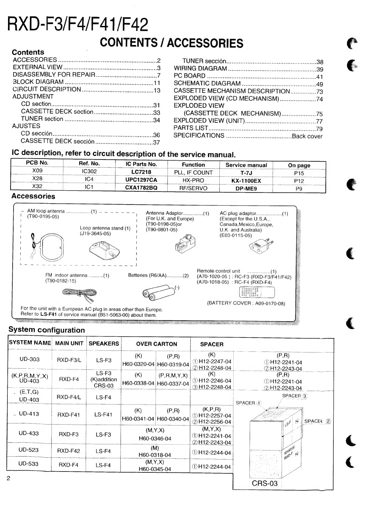
ACCESSORIES
0000.0...
ccceeccccccecsssscesenerceseesteeeseceeeeusenues
2
EXTERNAL
VIEW
............ceccecceccssseceesceecseesececeeteneeeee
3
DISASSEMBLY
FOR
REPAIR...
.cceccccesccccccccccceeeee
7
BLOCK
DIAGRAM
.......
cece
ceccececeecessesseceseceettereceeeees
11
CIRCUIT
DESCRIPTION
uu...
ecccccccccccseccccereecceeee
13
ADJUSTMENT
CDesecCtlontasetieS
ach
ae
edie)
oa
ne
31
CASSETTE
DECK
33
TUNER
Section
00.0...
cece
i
cccccecssesecscsceseececceceececces
34
AJUSTES
CD
SOCCION........ccccccseccescsseseeccssssesesesersecccesceesece,
36
CASSETTE
DECK
SeCCION
o.oo
eecccccccccccceccecceeees
37
TUNER
S6@CCION......
oe.
cecececccccceceseceesecsuccestneseeees
38
WIRING
DIAGRAM...
occ
cee
ccccccesecescesecsccesscesscees
39
PG
BOARD:
22.055.
228
su
eiteeavcc:
Seciheoac
naan
41
SCHEMATIC
DIAGRAM
........ecceccccesscccccecscceeecccesseees
49
CASSETTE
MECHANISM
DESCRIPTION..........00...
73
EXPLODED
VIEW
(CD
MECHANISM).................0.
74
EXPLODED
VIEW
(CASSETTE
DECK
MECHANISMM)....................
75
EXPLODED
VIEW
(UNIT).........
cc
ceeeeeeceeseeeeeceeseens
77
PARTS
LIST
fis
tetoliesenrctieetneleaichktetoecaadas
79
SPECIFICATIONS
o.oo
.eccccccccccccccecesseeeseeeeees
Back
cover
ie
IC
Parts
No.
Function
—_|_‘
Service
manual
_Onpage
_
__xo9-
|
C302
LC7218
PLLIFCOUNT
|
T-7J
|
PIB
X28
|
ca
UPC1297CA
HX-PRO
|
KX-1100EX)
|
P12
X32
IC1
CXA1782BQ
RF/SERVO
__DP-ME9
—
AM
loop
antenna
(T90-0195-05)
Loop
antenna
stand
(1)
(J19-3645-05)
FM
indoor
antenna
(T90-0182-15)
For
the
unit
with
a
European
AC
plug
in
areas
other
than
Europe.
Refer
to
LS-F41
of
service
manual
(B51-5063-00)
about
them.
Antenna
Adaptor.
(For
U.K.
and
Europe)
(T90-0198-05)or
(T90-0801-05)
G-
AC
plug
adaptor
(Except
for
the
U.S.A.,
Canada,Mexico,
Europe,
U.K.
and
Australia)
(E03-01
15-05)
Remote
contro!
unit
(A70-1020-05
)
:
RC-F3
(A70-1018-05)
:
RC-F4
(BATTERY
COVER
:
A09-0170-08)
|
MAIN
UNIT
SPEAKERS
OVER
CARTON
SPACER
feces
|
|
i
ae
i
.
(kK)
il
(P.R)
a,
(K)
is
oe
(P,R)
-
E
|
RXD-F9/L
—sLS-F3
GD)H12-2247-04
|
(DH12-2241-04
ie
Said
ee
te,
2
OO
ONE
OT
OO
08
DOF
oyna
oodg
04)
(DH12-2243-04
LS-F3
|
K)
P,R,M,Y,X)
(K)
|
(P,R)
(K,P,R,M,Y,X)
|
aye
(
(P,R,M,Y,X)
|
|
eg
UD-40
|
RXD-F4
|
(K)addition
-0398-
“naay
na)
DH12-2246-04
|
(DH12-2241-04
”
nS
rs-03_
H60-0338-04
|H60-0337-04)
-
H12-2248-04
|
_QH12-2243-04
-
(ET,G)
|
SPACER
3°
RXD-F4/L
|
LS-F4
Sencen
UD-403
ay)
|
ies
re
7
;
_
;
|
SPACER
PD
/
UD-413
|
LS-F41
(K)
Be
las
nyesees
04
LP
_
UD-
:
:
1)
H12-2257-
A
b
ee
H60-0341-04
|
H60-0340-04
>)
1445
9956.04
|
¢
8
|
SPACER
®
east
a
sate
wef
8 |
SPACER.
UD-433
Ss
ee
I)
oo
ae
.
RXD-F3
LS-F3
@)H12-2241-04
ian
en
H60-0346-04
|)
H12-2243-04
M)
UD-5
: :
(
@H12-2044-
D-523
RXD-F42
SF
ee
eit
)H12-2244-04
(MYX)
|
RXD-F4
LS-F4
mame
@H12-2244-04
aa