MRIaudio MRIaudioPREM-1000 User manual

MRIaudio IM-01 Rev. B, Jan 2017
0 of 13
InstallationManual
Model: MRIaudioPREM-1000 & MRIaudioPREM-1001
Have questions during installation?
We have answers.
(858) 427-0679
www.mriaudio.com

MRIaudio IM-01 Rev. B, Jan 2017
1 of 13
RecommendedTools:
RequiredTools:
CAUTION:
MRIaudio 3G Transducer contains a finite
amount of magnetic material and should be kept 3ft
away from the magnet’s bore. It can be harnessed
underneath the MRI using supplied transducer mount.
Over-Ear Headphones
29 dB NRR Part # 330 Y-Splitter
Part # 211
Pneumatic Tubing
Part # 220 BNC RF Shielded
Part # 203
DB9 RF Shielded
Part # 210
3G
T
ransducer
Part # 101
Digital Amplifier
Part # 600
T
echnologist Mic
Part # 669
T
echnologist
Speakers Part # 670
iPad & Stand
Part # 620, 630
(optional)
3.5mm to RCA
Cable Part # 625 BNC Coaxial Part # 202
DB9 Coaxial Part # 201
iN-Ear Headphones
29 dB NRR
Part # 320
SYSTEMOVERVIEW
The MRIaudioPREM-1001 & 1001 Patient Stereo is a pneumatic audio system composed of both MRI-
safe and MRI-unsafe components.
It is critically important that only MRI-safe and MRI-conditional components be taken into and
installed in the MRI suite.
When installed correctly, the MRIaudioPREM-1000 & 1001 system is MRI-compatible and will produce
high quality audio for patients undergoing MRI scans.
Fish Tape Electrical Tape
Miniature Flathead
Screwdriver
Zip TiesWire Lubricant
!BE
SU
REANYT
OO
L
S
C
ARRIEDINT
O
MRI
SU
ITEAREMRI-
S
AFE!
MRIaudioPREM-1000 MRIaudioPREM-1000
MRIaudioPREM-1001
MRIaudioPREM-1000
MRIaudioPREM-1001

MRIaudio IM-01 Rev. B, Jan 2017
2 of 13
Part Number Product Description
101 3G Transducer: MRI conditional audio transducer. Aluminum gray, cylindrical shape with BNC-F input, 1.5 and 3 Tesla tested.
101-10 Transducer Mount: Securely mounts 3G Transducer horizontally underneath the MRI. Uses double sided adhesive to secure
the mount to the ground and prevent vibration. Includes 18" black velcro strap to harness 3G Transducer to mount.
201 100' Non-Shielded Gray Coaxial PigTail to DB9-F Cable: Connects MRIaudio digital amplifier to penetration panel in equipment
room.
202 100' Non-Shielded Gray Coaxial PigTail to BNC-M Cable: Connects MRIaudio digital amplifier to penetration panel in equipment
room.
210 45' RF Shielded RG6 Black BNC-M to DB9-M Cable: Connects 3G Transducer to penetration panel inside of the MRI suite.
203 45' RF Shielded RG6 Black BNC-M to BNC-M Cable: Connects 3G Transducer to penetration panel inside of the MRI suite.
220 9' Pneumatic Tubing: Connects both headphones to 3G Transducer; nylon mono tube with gray sheathing. One
proprietary 3G Transducer connection end; one standard two prong headphone connection end.
300 Ear-Tip 250: 250 pairs (500 count) of disposable ear-tips. Designed to work with MRIaudio iN-Ear headphones. 1" tall x .5" wide;
plug shape, turquoise color, PU Foam with silicone core. Provides patients with 29 decibels of hearing protection.
320 In-Ear Headphones: Connects to pneumatic tubing, fits inside all MRI coils. Provides patients with 29 decibels of hearing
protection. Light gray removable headband, 3 feet of dual pneumatic tubing with ear inserts, and a sample pack of
disposable ear-tips included.
330 Over Ear headphones: Connect to pneumatic tubing, provide patients with 29 decibels of hearing protection. Adjustable
headband, silicon ear cushions, black color.
600 Digital Amplifier: 35 watt digital amplifier with mixer. Powers 3G Transducer and sends audio signal to Technologist Speakers.
Three audio inputs with individual front panel volume, bass, and treble tone controls.
600-10 Universal Power Supply for Digital Amplifier: 24 volt DC, 2 amp output,100-240 volt AC input, Energy Star level 5 compliant.
Includes 6' AC power cord plug type B.
600-25 6' AC Power Cord Plug Type B: Connects digital amplifier’s power supply to wall outlet. Female connector plugs directly into
the universal power supply while the male connector plugs into a standard type B outlet.
620 Customized iPad: 16 GB iPad Mini with Wi-Fi. Pre-programmed with internet streaming music applications.
620-30 USB Power Adaptor with 3' Lightning to USB Cable-Type B Plug: Intended to charge iPad. Includes 6' USB extension cord.
625 6' 3.5mm to RCA Cable: Connects any music source (with a 3.5mm jack) to MRIaudioPREM system.
630 iPad Stand: iPad Mini stand enclosure with security lock and key. Desktop anti-theft protection accessory. Gray color, weighted
base, rotating iPad enclosure can be tilted and flipped both horizontally and vertically.
670 Bose Technologist Speakers: Two speakers, allows technologist to listen to the same music as the patient. Independent
volume control included on master speaker. Includes power supply with 5’8” extension, type B (US/Canada) outlet.
670-20 Power Supply for Bose Technologist Speakers: Power supply plug with 5'8" extension, type B (US/Canada) input 100-240 volt
50/60
Herts 360 Mili Amp, Output 12volt DC .833 Amps.
670-36 Bose Technologist Speaker Cable Assembly: Connects Bose Technologist Speakers to amplifier.
669 Shure 450 Series II: Technologist to patient microphone connects to the back of the amplifier.
SYSTEMCOMPONENTS

MRIaudio IM-01 Rev. B, Jan 2017
3 of 13
PartNumber Description CableLength(Feet)
669 Shure450SeriesIIMicrophone 3’
600‐10 UniversalPowerSupply 11’
620‐30 USBPoweradaptor3’LightningUSB;Includes6’USBextension 9’
670‐20 PowersupplyforBoseTechnologistSpeakers 5’8”
625 6’3.5mmtoRCACable 6’
201&202 100’Non‐ShieldedGrayCoaxialCablewithPigTail 100’
210&203 45’RFShieldedRG6blackwithBNC 45’
220 9’PneumaticTubing 9’
670‐36 3’Bose Technologist speaker wire assembly3’
SYSTEMMAP
The system maps below provide an overview of the MRIaudioPREM-1000 & 1001 system installation.
Please refer to subsequent pages for detailed, step-by-step instructions when installing the
system. Be sure to read all instructions before installing the MRIaudioPREM-1000 & 1001 System
Inspect each component for any visible damage. If damage is noted, do not perform the
installation.
Warning: Serious injury could result if metallic/magnetic material is brought into the MRI suite
MRIaudio IM-01 Rev. B, Jan 2017
4 of 13
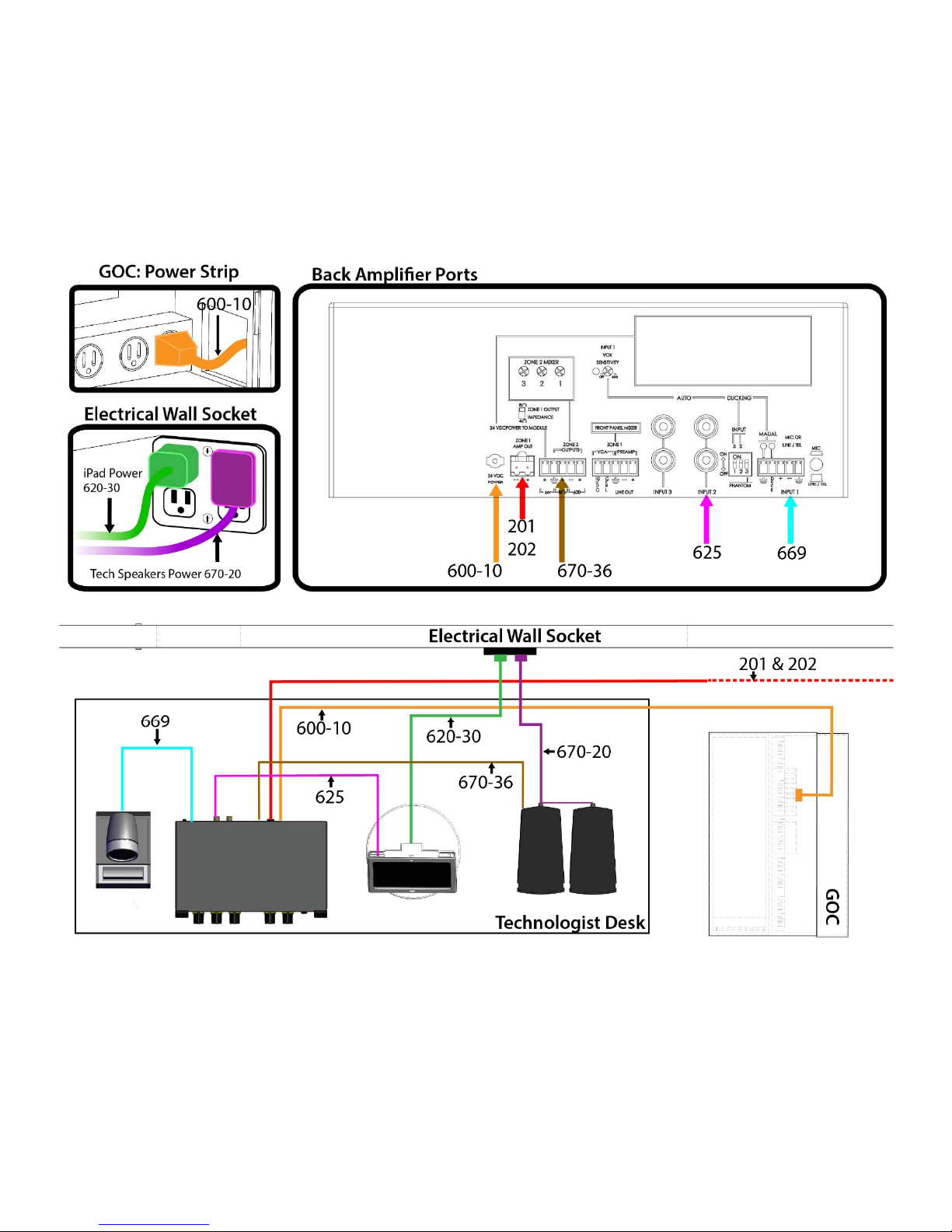
AMPLIFIERMAP
The amplifier map below provides an overview of the digital amplifier.
Please refer to subsequent pages for detailed, step-by-step instructions on how to tune & properly
install cable assemblies.
NOTE: The digital amplifier should be pre-tuned from the MRIaudio factory.
This manual suits for next models
1
Table of contents
Other MRIaudio Stereo System manuals


