hilton 520 User manual
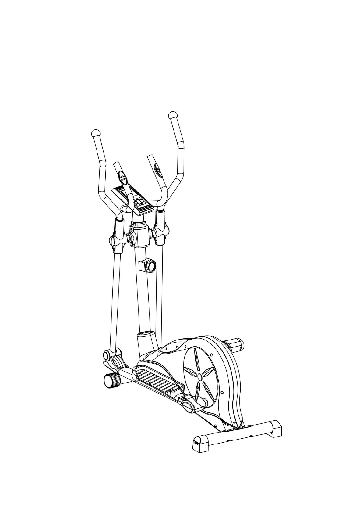
520
MAGNETIC
ELLIPTICAL TRAINER

1
Important Safety Information
Please keep this manual in a safe place for reference.
1. It is important to read this entire manual before assembling and using the equipment.
Safe and efficient use can only be achieved if the equipment is assembled,
maintained and used properly.It is your responsibility to ensure that all users of the
equipment are informed of all warnings and precautions.
2. Before starting any exercise program you should consult your doctor to determine if
you have any physical or health conditions that could create a risk to your health and
safety, or prevent you from using the equipment properly.Your doctor's advice is
essential if you are taking medication that affects your heart rate, blood pressure or
cholesterollevel.
3. Be aware of your body's signals. Incorrect or excessive exercise can damage your
health. Stop exercising if you experience any of the following symptoms: Pain,
tightness in your chest, irregular heartbeat,extreme shortness of breath, feeling
light headed,dizzy or nauseous. If you do experience any of these conditions. you
should consult your doctor before continuing with your exercise program.
4. Keep children and pets away from the equipment. The equipment is designed for
adult use only.
5. Use the equipment on a solid, flat level surface with a protective cover for your floor
or carpet. For safety, the equipment should have at least 0.5 metre of free space all
around it.
6. Before using the equipment, check the nuts and boits are securely tightened.
7. The safety level of the equipment can only be maintained if it is regularly examined
for damage and/or wear and tear.
8. Always use the equipment as indicated.If you find any defective components whilst
assembling or checking the equipment,or if you hear any unusual noise coming from
the equipment during use,stop. Do not use the equipment until the problem has been
rectified.
9. Wear suitable clothing whilst using the equipment. Avoid wearing loose clothing
which may get caught in the equipment or that may restrict or prevent movement.
10.The equipment has been tested and certified to EN957 under class H.C. Suitable
for domestic,home use only. Maximum weight of user, 130Kg. Breaking is speed
independent.
11.The equipment is not suitable for therapeutic use.
12.Care must be taken when lifting or moving the equipment so as not to injureyour
back. Always use proper lifting techniques and/or use assistance.
2

3
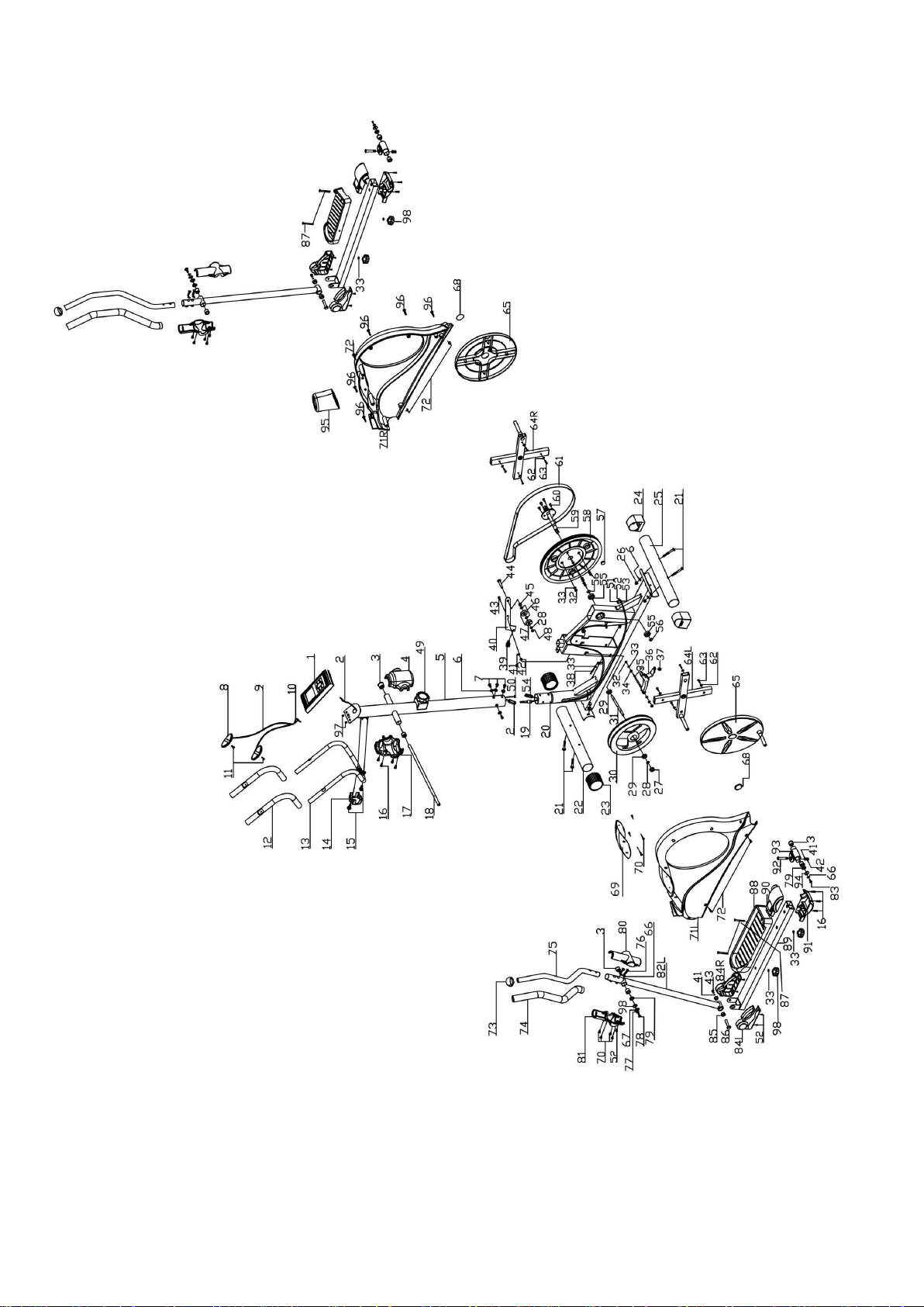
Parts list
Nr
Description
Quantity
1
Computer
1PC
2
Upper Computer Cable
1PC
3
Powder Metallurgy (or Bushing) D28
10PCS
4
Cover for Handlebar Post (Front)
1PC
5
Handlebar Post
1SET
6
M8 Curved Washer Ø20*Ø8.2*1.2T
8PCS
7
Allen Key Bolt M8*16
4PCS
8
Hand pulse Grip
1SET
9
Hand pulse Cable
1SET
10
Hand pulse Plug
1PC
11
Self-tapping Screw M4*25
2PCS
12
Fixed Handlebar Foam
2PCS
13
Fixed Handlebar
1PC
14
Fixed Handlerbar Cover
1PC
15
Allen Key Bolt M8*30
2PCS
16
Self-tapping Screw M4*20
10PCS
17
Cover for Handlebar Post (Back)
1PC
18
Handlebar Axle
1PC
19
Lower Computer Cable
1PC
20
Main Frame
1SET
21
Carriage Bolt M8*70
4PCS
22
Front Stabilizer
1PC
23
Front Stabilizer Cap
2PCS
24
Rear Stabilizer
2PCS
25
Rear Stabilizer Cap
1PC
26
Domed Nut M8
4PCS
27
Flange Nut 3/8"
2PCS
28
Flat Washer M10
2PCS
29
Bearing 6001zz
2PCS

4
30
Flywheel Φ260
1PC
31
Flywheel Axle
1PC
32
M6 Nylon Nut
6PCS
33
Flat Washer Ø18*Ø6.2*1.0
15PCS
34
M6 Nut
2PCS
35
Double-ended screw Ø6*75
1PC
36
Magnet Set
1SET
37
Spring
1PC
38
Bolt M6*70
1PC
39
Spring Hook
1PC
40
Fixing plate for idle wheel
1PC
41
Flash Washer Ø20*Ø8.2*1.2T
5PCS
42
M8 Anti-lose Ø20*Ø8.2*1.2T
3PCS
43
Bolt M8*25L
1PC
44
Bolt M10*40
1PC
45
Bushing Φ14*1.5T*6L
1PC
46
Flat Washer Ø14*Ø10*1.0T
2PCS
47
Bearing 6300Z
2PCS
48
Nylon Nut M10
1PC
49
knob
1PCS
50
Upper knob cable
1SET
51
Upper tension cable
1PC
52
Screw M5*15L
11PCS
53
Sensor
1PC
54
lower knob cable
1PC
55
Bearing 6300ZZ
2PCS
56
Φ17 C-Clip
2PCS
57
Magnet
1PC
58
Belt Wheel Φ260
1PC
59
Crank Axle
1SET
60
Bolt M6*15
4PCS
61
Belt 430J
1PC

5
62
Flat Washer Ø18*Ø5.2*1.0
8PCS
63
Self-tapping M5*17
8PCS
64
Crank(L+R)
2SET
65
Round Cover
2PCS
66
Spring washer M6
6PCS
67
Big washer Ø28*Ø16*1.5T
2PCS
68
Side Cover
2PCS
69
Top Cover (L+R)
2SET
70
Self-tapping M4*12
14PCS
71
Chain Cover (R+L)
2SET
72
Screw M5*15
8PCS
73
Handlebar Cap
2PCS
74
Moveable handlebar Foam
2PCS
75
Moveable handlebar
2PCS
76
Allen Key Bolt M8*35
4PCS
77
Spring Washer Ø17*Ø10.2*2.0T
2PCS
78
Allen Key Bolt M10*25
2PCS
79
Sea Washer Ø25*Ø17*0.5T
4PCS
80
Moveable handlebar Cover (Front)
2PCS
81
Moveable handlebar Cover (Back)
2PCS
82
Moveable handlebar support (R+L)
2SET
83
Allen key bolt M8*20
4PCS
84
Cover for pedal (R+L)
2SET
85
Bushing
4PCS
86
Front Pedal Axle
2PCS
87
Bolt M6*15
8PCS
88
Pedal (R+L)
2PCS
89
Pedal Support Tube
2SET
90
Cover for universal axle (upper)
2PCS
91
Cover for universal axle (lower)
2PCS
92
Allen Key Bolt M8*50
2PCS
93
Universal Joint
2SET

6
94
Washer Ø28*Ø8.2*1.5T
2PCS
95
Front Cover
1PC
96
Self-tapping M5*25
7PCS
98
Washer Ø28*Ø16*4.5T
2PCS
99
Screw M5
2PCS

7
STEP I
Attach the front stabilizer (22) to the main frame (20) with 2 sets of M8*70 Carriage Bolt
(21), Ø20*Ø8.2*1.2T M8 Curved Washer (6),spring washer (66)and M8 Domed Nut
(26).
Attached the rear stabilizer (25) to the main frame (20) with 2 sets of M8*70 Carriage Bolt
(21), Ø20*Ø8.2*1.2T M8 Curved Washer (6) , spring washer(66)and M8 Domed Nut
(26).

8
STEP2
Insert the handlebar post (5) to the front cover (95).
Connect the upper company cable (2) with lower computer cable (19)knob cable(50)
(54)
Attach the handlebar post (5) to the main frame with 3 sets of Ø20*Ø8.2*1.2T M8 Curved
Washer (6) and M8*16 Allen Key Bolt (7).

9
Step 3:
Attach the Pedal (88) on to the pedal support tube (89) with 2 sets of bolt (87),washer
(33)and knob (98)

10
STEP4
1. Position the handlebar axle (18) in the handlebar post (5)
2. Connect moveable handlebar support (82R+82L) to the handlebar axle with 1pcs of
Sea Washer Ø25*Ø17*0.5T(79) ,D-washer Ø28*Ø16*4.5T (98), Flat washer (67),
spring washer (77),sea washer Ø25*Ø17*0.5T (79) and M10*25 Allen key bolt (78)
on each side.
3. Attach the pedal support tube (89R+89L) to the main frame with 1pcs of
Ø28*Ø8.2*1.5T washer (94), sea washer Ø25*Ø17*0.5T (79), spring washer (66) and
M8*20 Allen key bolt (83) on each side.
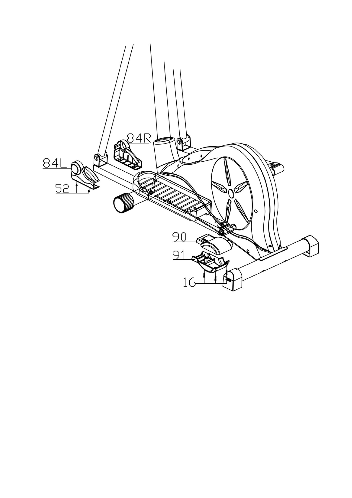
11
STEP5:
1. Attach the Pedal cover (84L+84R) on to the joint with 2 sets of M5*15L screw (52) on
each side.
2. Attach the universal axle cover (front) (90) and universal axle cover (back) (91) on to
the pedal support tube (89) with 3 sets of self-tapping screw M4*20 (16)

12
STEP6
Slide in moveable handlebars (75) and tighten will by using 2 sets of M8*35 Allen key
bolt on each side.
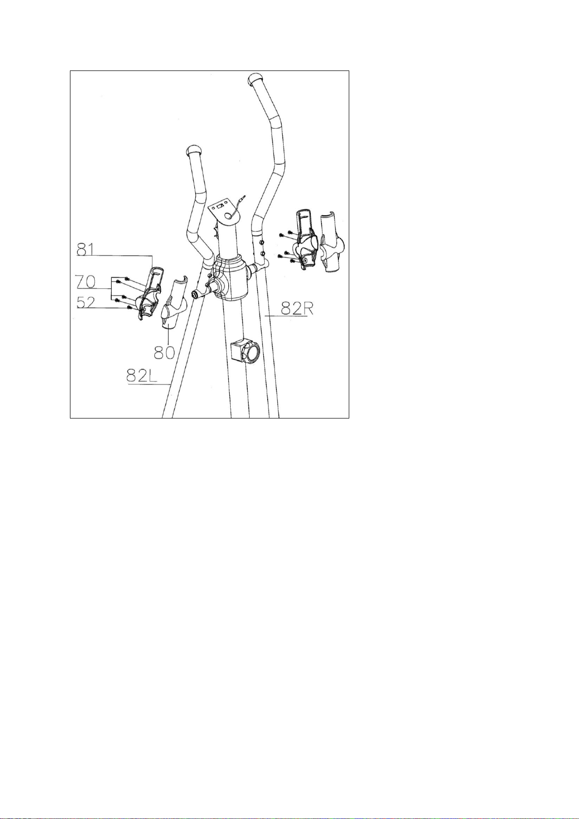
13
STEP7
Attach the moveable handlebar cover (front) (80) and moveable handlebar cover (back)
(81) on to the joint of moveable handlebar and handlebar support (82L+82R) with 4 sets
of M4*12 self –tapping screw and M5*15 screw as show on the picture for each side.
14
STEP8
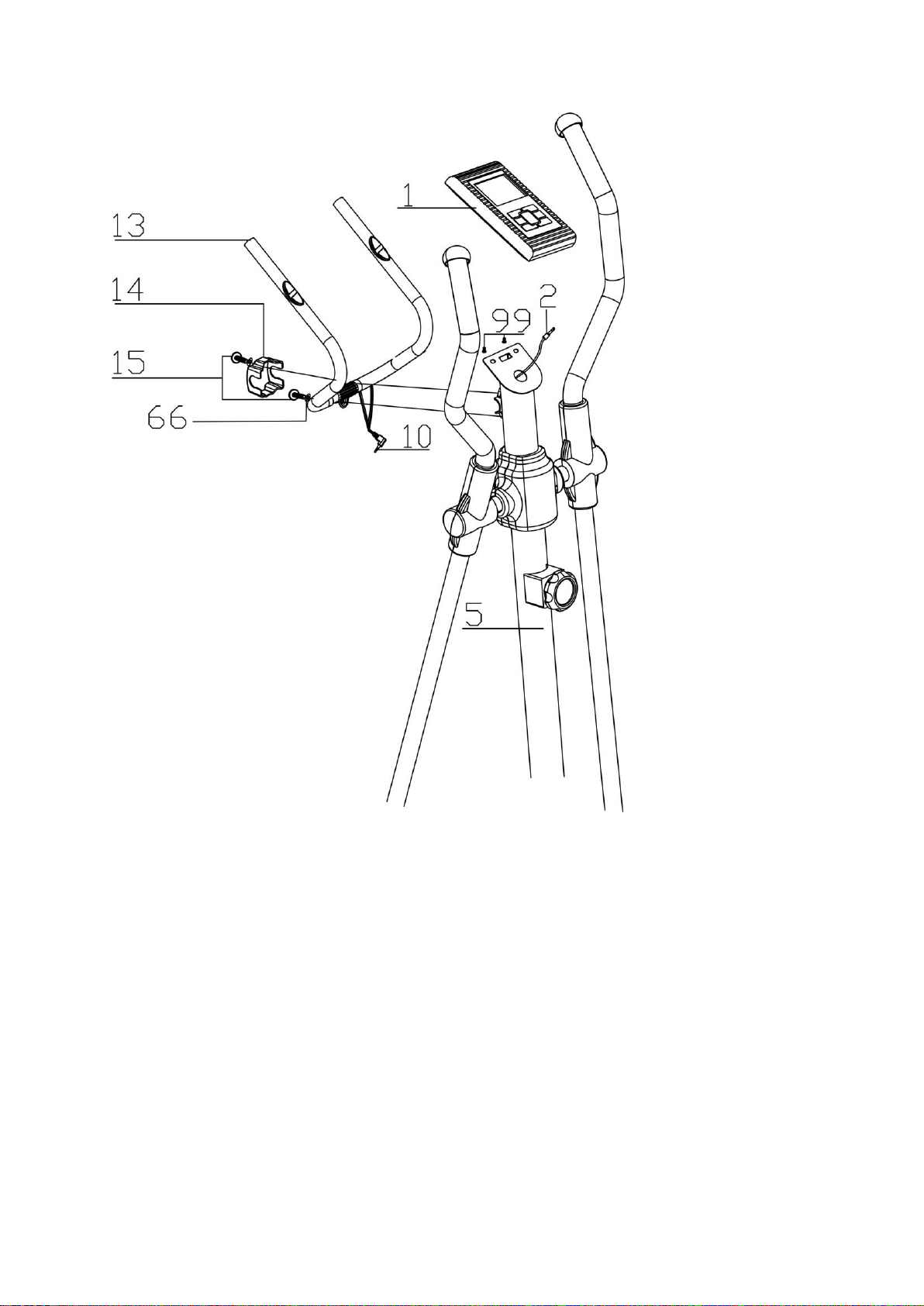
1. Attach the fixed handlebar (13) on to the handlebar post (5) with 2 sets of M8*30
Allen key bolt, cover it with the fixed handlebar cover (14).
2. Connect the computer (1) with the upper computer cable (2), and fix the computer by
using the screws which were already attached at the back of the computer.
3. Inset the handle pulse plug (10) into the back of the computer (1)

15
EXERCISE INSTRUCTIONS
Using your EXERCISE CYCLE will provide you with several benefits, it will improve your
physical fitness, tone muscle and in conjunction with calorie controlled diet help you lose
weight.
1. The Warm Up Phase
This stage helps get the blood flowing around the body and the muscles working properly.
It will also reduce the risk of cramp and muscle injury. It is advisable to do a few
stretching exercises as shown below. Each stretch should be held for approximately 30
seconds, do not force or jerk your muscles into a stretch - if it hurts, STOP.
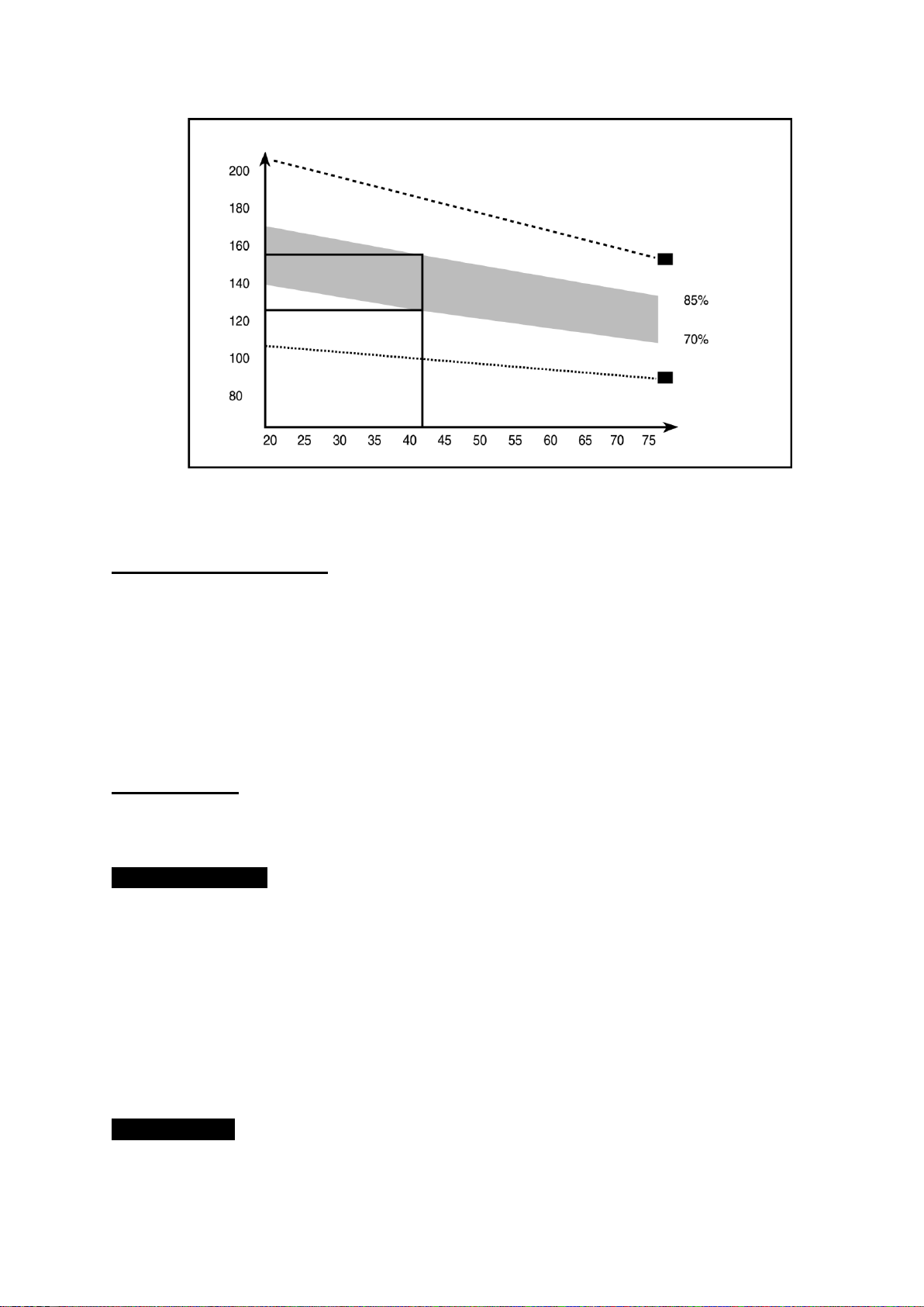
2. The Exercise Phase
This is the stage where you put the effort in. After regular use , the muscles in your legs
will become more flexible. Work to your own pace but it is very important to maintain a
steady tempo throughout. The rate of work should be sufficient to raise your heart beat
into the target zone shown on the graph below.
SIDE BENDS
FORWARD
BENDS
OUTER THIGH
INNER THIGH
CALF /ACHILLES
16
This stage should last for a minimum of 12 minutes though most people start at about
15-20 minutes.
3. The Cool Down Phase
This stage is to let your Cardio-vascular System and muscles wind down. This is a
repeat of the warm up exercise e.g. reduce your tempo, continue for approximately 5
minutes. The stretching exercises should now be repeated, again remembering not to
force or jerk your muscles into the stretch. As you get fitter you may need to train longer
and harder. It is advisable to train at least three times a week, and if possible space your
workouts evenly throughout the week.
4. Fault Finder
1. If you do not receive numbers appearing on your computer, please ensure all
connections are correct.
MUSCLE TONING
To tone muscle while on your EXERCISE CYCLE you will need to have the resistance
set quite high. This will put more strain on your leg muscles and may mean you cannot
train for as long as you would like. If you are also trying to improve your fitness you need
to alter your training program. You should train as normal during the warm up and cool
down phases, but towards the end of the exercise phase you should increase resistance
making your legs work harder. You will have to reduce your speed to keep your heart rate
in the target zone.
WEIGHT LOSS
The important factor here is the amount of effort you put in. The harder and longer you
HEART RATE
TARGET ZONE
MAXIMUM
COOL DOWN
AGE

17
work the more calories you will burn. Effectively this is the same as if you were training to
improve your fitness, the difference is the goal.
USE
The seat height can be adjusted by removing the adjustment knob and raising or
lowering the seat. There are 7 holes in the seat post allowing for a range of heights.
Once the correct height has been chosen, refit the adjustment knob and tighten. The
tension control knob allows you to alter the resistance of the pedals. A high resistance
makes it more difficult to pedal; a low resistance makes it easier. For the best results set
the tension while the bike is in use.

18
Computer
A. User Data:
You should input your personal data before workout. Press BODYFATkey to enter your personal data
of sex, age, height and weight then the computer can save the data unless take out the batteries.
B. SLEEP MODE:
The monitor will entry SLEEP mode (LCD off) when there is no signal input and no key be pressed
after 4 minutes.
Functions and Features:
1. TIME: Shows your elapsed workout time in minutes and seconds. Your computer will automatically
count up from 0:00 to 99:99 in one second intervals. You many also program your computer to
count down from a set value by using the UP and DOWN keys from 0:00 to 99:00. If you continue
exercising once the time has reached 0:00, the computer will begin beeping, and reset itself to the
original time set, letting you know your workout is done.
2. SPEED: Displays your workout speed value in KM/MILE per hour.
3. DISTANCE: Displays the accumulative distance traveled during each workout up to a maximum of
99.9KM/MILE.
4. CALORIES: Your computer will estimate the cumulative calories burned at any given time during
your workout.
5. PULSE: Your computer displays your pulse rate in beats per minute during your workout.
6. RPM: Your pedal cadence.
Key function:
There are 6 button keys and the function description as follows:
1. UPkey: During the setting mode, press the key to increase the value of Time, Distance, Calories,
Age, Weight, Height etc. and to select sex. During the CLOCK mode, you can set up
clock and alarm by this key.
2. DOWN key: During the setting mode, press the key to decrease the value of Time, Distance,
Calories, Age, Weight, Height etc. and to select sex. During the CLOCK mode, you
can set up clock and alarm by this key.
Note: During the setting mode, you can hold UP and DOWN keys together for over two seconds

19
then the setting value will reset to Zero or default value.
3. ENTER/RESET key: a. Press the key to accept the current data entry.
b. During the no speed mode, by holding this key for over two seconds then the
computer will re-power-on.
4. BODY FAT key: Press the key to enter your personal data before measure your body fat ratio.
5. MEASURE key: Press the key to get your body fat ratio and BMI and BMR.
a. FAT %: Indicate your body fat percentage after measurement.
b. BMI (Body Mass Index): BMI is a measure of body fat based on height and weight that
applies to both adult men and women.
c. BMR (Basal Metabolic Rate): Your Basal Metabolic Rate (BMR) shows the number of
calories your body needs to operate. This doesn’t account for any activity, it’s simply the
energy needed to sustain a heartbeat, breathing and normal body temperature. It measures
the body at rest, not sleep, at room temperature.
6. PULSE RECOVERY key: Press the key to activate heart rate recovery function.
F=1.0 means OUTSTANDING
1.0<F<2.0 means EXCELLENT
2.0≦F≦2.9 means GOOD
3.0≦F≦3.9 means FAIR
4.0≦F≦5.9 means BELOW AVERAGE
F=6.0 means POOR
Error Message:
E: The speed over than 999.9 MPH/KPH then the computer will display “E”.
Err: When measure the body fat function or pulse recovery function, if there is no pulse signal input
within 20 seconds
then the computer will display “Err”. You can repress any keys to quit the Err message.
How to replace the batteries:
Please move out the battery cover from the bottom housing then replace the batteries.
This manual suits for next models
1
Table of contents
Popular Elliptical Trainer manuals by other brands

Merrithew
Merrithew Tower Trainer owner's manual

DKN technology
DKN technology XC-190 manual

Everlast
Everlast 16517126 owner's manual

Westinghouse
Westinghouse WE02 OPERATING MANUAL, INSTALLATION STEPS

Christopeit Sport
Christopeit Sport CT 400 Assembly and exercise instructions

Horizon Fitness
Horizon Fitness HZ SERIES EX-22 user guide


