Hiltron THC20IP User manual

HD IR Waterproof Fixed Network Camera
(With Integrated Bracket)
User’s Manual
Version 4.0.0

i
Welcome
Thank you for purchasing our network camera!
This user’s manual is designed to be a reference tool for your system.
Please read the following safeguard and warnings carefully before you use this series product!
Please keep this user’s manual well for future reference!

ii
Important Safeguards and Warnings
1᧪
᧪
Electrical safety
All installation and operation here should conform to your local electrical safety codes.
The power shall conform to the requirement in the SELV (Safety Extra Low Voltage) and the Limited
power source is rated 12V DC or 24V AC in the IEC60950-1. (Refer to general introduction) Please
note: Do not connect two power supplying sources to the device at the same time; it may result
in device damage!
We assume no liability or responsibility for all the fires or electrical shock caused by improper handling
or installation.
We are not liable for any problems caused by unauthorized modification or attempted repair.
2
᧪
Transportation security
Heavy stress, violent vibration or water splash are not allowed during transportation, storage and
installation.
3
᧪
Installation
Do not apply power to the camera before completing installation.
Please install the proper power cut-off device during the installation connection.
Always follow the instruction guide the manufacturer recommended.
4
᧪
Qualified engineers needed
All the examination and repair work should be done by the qualified service engineers.
We are not liable for any problems caused by unauthorized modifications or attempted repair.
5
᧪
Environment
This series network camera should be installed in a cool, dry place away from direct sunlight,
inflammable, explosive substances and etc.
Please keep it away from the electromagnetic radiation object and environment.
Please make sure the CCD (CMOS) component is out of the radiation of the laser beam device.
Otherwise it may result in CCD (CMOS) optical component damage.
Please keep the sound ventilation.
Do not allow the water and other liquid falling into the camera.
Thunder-proof device is recommended to be adopted to better prevent thunder.
The grounding studs of the product are recommended to be grounded to further enhance the reliability
of the camera.
6. Daily Maintenance
Please shut down the device and then unplug the power cable before you begin daily maintenance
work.

iii
Do not touch the CCD (CMOS) optic component. You can use the blower to clean the dust on the lens
surface.
Always use the dry soft cloth to clean the device. If there is too much dust, please use the water to
dilute the mild detergent first and then use it to clean the device. Finally use the dry cloth to clean the
device.
Please put the dustproof cap to protect the CCD (CMOS) component when you do not use the camera.
Dome enclosure is the optical component, do not touch the enclosure when you are installing the
device or clean the enclosure when you are doing maintenance work. Please use professional optical
clean method to clean the enclosure. Improper enclosure clean method (such as use cloth) may result
in poor IR effect of camera with IR function.
7. Accessories
Be sure to use all the accessories recommended by manufacturer.
Before installation, please open the package and check all the components are included.
Contact your local retailer ASAP if something is broken in your package.
Accessory Name
Amount
Network Camera
Unit
1
Quick Start Guide
1
Installation Accessories Bag
1
12V to 24V Conversion Cable
(For AC 24V series product only)
1
CD
1

iv
Table of Contents
1General Introduction ......................................................................................................1
1.1 Overview ...........................................................................................................1
1.2 Features............................................................................................................1
1.3 Specifications....................................................................................................2
1.3.1 Performance ...............................................................................................2
1.3.2 Factory Default Setup .................................................................................4
2Structure......................................................................................................................11
2.1 Multiple-function Combination Cable...............................................................11
2.2 Framework and Dimension .............................................................................12
2.3 Bidirectional talk ..............................................................................................13
2.3.1 Device-end to PC-end...............................................................................13
2.3.2 PC-end to the Device-end.........................................................................13
2.4 Alarm Setup ....................................................................................................14
3Installation ...................................................................................................................16
3.1 Device Installation ...........................................................................................16
3.2 Micro SD Card Installation ..............................................................................17
3.3 Lens Adjustment .............................................................................................19
3.4 Bracket Adjustment .........................................................................................19
3.5 OSD Buttons (For Motorized Zoom Lens Series Product Only) ......................21
4Quick Configuration Tool .............................................................................................23
4.1 Overview .........................................................................................................23

v
4.2 Operation ........................................................................................................23
5Web Operation ............................................................................................................25
5.1 Network Connection........................................................................................25
5.2 Login and Main Interface.................................................................................25
6FAQ .............................................................................................................................28
7Appendix Toxic or Hazardous Materials or Elements ..................................................29

1
1 General Introduction
1.1 Overview
This series network camera integrates the traditional camera and network video technology. It adopts
audio and video data collection, transmission together. It can connect to the network directly without
any auxiliary device.
This series network camera product uses standard H.264 video compression technology and G.711a
audio compression technology, which maximally guarantee the audio and video quality.
It supports the IR night vision function. In the night environments, the device can use the IR light to
highlight the object which is suitable for the surveillance function in the low illumination environments.
The built-in protection enclosure and waterproof design conforms to the IP 66 level. It has the sound
waterproof function suitable for use in the outdoor environments.
It supports real-time monitor and listening at the same time. It supports analog video output and dual-
way bidirectional talk.
It can be used alone or used in a network area. When it is used lonely, you can connect it to the
network and then use a network client-end. Due to its multiple functions and various uses, this series
network camera is widely used in many environments such office, bank, road monitor and etc.
1.2 Features
User
Management
zDifferent user rights for each group, one user belongs to one group.
zThe user right shall not exceed the group right.
Storage
Function
zSupport central server backup function in accordance with your configuration and
setup in alarm or schedule setting
zSupport record via Web and the recorded file are storage in the client-end PC.
zSupport built-in Micro SD card.
zDo not support local Micro SD card hot swap storage function. Support short-time
storage when encounter disconnection.
zSupport network storage function such as FTP.
Alarm
Function
zReal-time respond to external on-off alarm input, and video detect as user pre-
defined activation setup and generate corresponding message in screen and
audio prompt(allow user to pre-record audio file)
zReal-time video detect: motion detect, camera masking.
Network
Monitor
zNetwork camera supports one-channel audio/video data transmit to network
terminal and then decode. Delay is within 270ms (network bandwidth support
needed)
zMax supports 20 connections.
zAdopt the following audio and video transmission protocol: HTTP, TCP, UDP,
MULTICAST, RTP/RTCP, RTSP and etc.
zSupport web access.
Network
Management
zRealize network camera configuration and management via Ethernet.
z
Support device management via web or client-end.
Power
zExternal power adapter DC12V/AC 24V. You can select according to your actual
environments. Please note system can not support these two types of power
supplying at the same time.
Assistant
Function
zLog function
zSupport system resource information and running status real-time display.

2
zDay/Night mode auto switch.
zBuilt-in IR light. Support IR night vision.
zSupport picture parameter setup such as electronic shutter and gain setup.
zBacklight compensation: screen auto split to realize backlight compensation to
adjust the bright.
zSupport video watermark function to avoid vicious video modification.
zThe enclosure conforms to the IP 66 protection. Has the waterproof function.
1.3 Specifications
1.3.1 Performance
Please refer to the following sheet for network camera performance specification.
Model
Parameter
HFW3300C
HFW3200C
HFW3100C
HFW3101C
System
Main Processor
TI Davinci high performance DSP
OS
Embedded LINUX
System
Resources
Support real-time network, local record, and remote operation at the same
time.
User Interface
Remote operation interface such as WEB, DSS, PSS
System Status
Micro SD card status, bit stream statistics, log, and software version.
Video Parameter
Image Sensor
1/2.8-inch
CMOS
1/2.9-inch
CMOS
1/3.0-inch CMOS
Pixel
2080(H)*1553(V
)
1920(H)*1080(V)
Day/Night Mode
Support day/night mode switch and IR-CUT at the same time. (The lens
has built-in IR-CUT mechanical component.).
Auto Aperture
Enable
Gain Control
Fixed/Auto
White Balance
Manual/Auto
BLC
Off/BLC/WDR (1-100 adjustable)/HLC(anti-flicker is outdoor and is valid
only when exposure mode is auto with range 1-100)
Exposure Mode
Manual/Auto
PAL: It ranges from 1/3 to 1/10000
NTSC: It ranges from 1/4 to 1/10000
Video
Compression
Standard
H.264/ H.264H/H.264B/MJPEG
Video Frame
Rate
PAL:
Main stream
(3M@15fps,108
0P@25fps,SXG
A@25fps,1.3M
@25fps,720P@
25fps,D1@25fps
)
Extra stream
(D1@25fps,
CIF@25fps)
PAL:
Main stream
(1080P@25fps,
SXGA@25fps,1.
3M@25fps,720P
@25fps,D1@25f
ps)
Extra stream
(D1@25fps,CIF
@25fps)
PAL:
Main stream
(1.3M@25fps, 720P@25fps,
D1@25fps)
Extra stream
(D1@25fps, CIF@25fps)
NTSC˖
Main
stream
(3M@15fps
,108
0P@30fps,
SXGA@30fps,
1.3M@30fps,
NTSC˖
Main stream
(1080P@30fps,
SXGA@30fps,
1.3M@30fps,
720P@30fps,
NTSC˖
Main stream˖
(1.3M@30fps, 720P@30fps,
704*480@30fps)
Extra stream
(704*480@30fps,352*240@30fps)

3
720P@30fps,
704*480@30fps
)
Extra
stream
(704*480@30fp
s,352*240@30fp
s)
704*480@30fps
)
Extra stream
(704*480@30fp
s,352*240@30fp
s)
Video Bit Rate
H.264: 56Kbps-8192Kbps.
H.264H 16Kbps-8192Kbps
H.264B 56Kbps-8192Kbps
MJPEG is adjustable and bit rate is adjustable.
Support customized setup.
Video Flip
Support mirror.
Support flip function.
Snapshot
Max 1f/s snapshot. File extension name is JPEG.
Privacy Mask
Supports max 4 privacy mask zones
Video Setup
Support parameter setup such as bright, contrast.
Video
Information
Channel title, time title, motion detect, camera masking.
Lens
Lens Interface
Φ14 interface. Lens is the default accessories
Audio
Audio Input
1-channel. RCA
Audio Output
1-channel. RCA
Bidirectional
Talk Input
Reuse the first audio input channel
Audio Bit Rate
16kbps 16BIT
Audio
Compression
Standard
G.711A
/G.711Mu/PCM
Video
Motion Detect
396 (18*22) detection zones; sensitivity level ranges from 0 to 100; area
threshold ranges from 0 to 100.
Activation event: video storage, image snapshot, log, email function and
etc.
Alarm Input
2-channel input
ˈ
1-channel output
Record and
Backup
Record Priority
Manual>External alarm >Video detect>Schedule
Local Storage
Support Micro SD card storage
Storage
Management
Support display local storage status
Network
Wire Network
1-channel wire Ethernet port, 10/100 Base-T Ethernet
Network Protocol
Standard HTTP, TCP/IP, ARP, IGMP, ICMP, RTSP, RTP,UDP, RTCP,
SMTP, FTP, DHCP, DNS, DDNS, PPPOE, UPNP, NTP, Bonjour, SNMP.
Remote
Operation
Monitor, system setup, file download, log information, maintenance ,
upgrade and etc.
AUX
Interface
Video Output
1-channel analog video output
ˈ
BNC port.
Restore Default
Setup
Reset button
Power
Support AC24V/DC12V power. (Can not support these two modes at the
same time.)
Gene
ral
Para
mete
Power
Consumption
8W MAX (10W MAX when ICR switch)
Working
-10
ć
~+60
ć

4
Temperature
Working
Humidify
10%~90%
Dimensions(mm)
φ104*306.7
Weight
1250g(Excluding box)
Installation
Bracket is included in the accessories bag.
IR Distance
20~30m
Protection Level
IP66
1.3.2 Factory Default Setup
Please refer to the following sheet for factory default setup information.
Setup
Item
Default Setup
HFW3300C
HFW3200C
HFW3100C
HFW3101C
Camera
Conditions
Config File
Normal
Brightness
50
Contrast
50
Saturation
50
Sharpness
50
Anti-flicker
Outdoor
Exposure Mode
Auto
Scene Mode
Auto
Day/night Mode
Auto
BLC
Off
Mirror
Off
Flip
Off
Profile Management
Normal
Video
Video bit stream
Main
Stream
Bit stream
type
General
Encode
mode
H.264
Resolution
1080P(1920*1080)
1.3M
˄
1280*960
˅
Frame
Rate(FPS)
PAL:25
NTSC:30
Bit Rate
Type
CBR
Recommen
ded Bit
3584
-8192 Kb/S
1536
-8192Kb/s
Bit Rate
8192
6144
I Frame
50
Watermark
Enable
Watermark
character
DigitalCCTV
Sub
Stream
Enable
Enable
Bit stream
General

5
Setup
Item
Default Setup
HFW3300C
HFW3200C
HFW3100C
HFW3101C
type
Encode
mode
H.264
Resolution
PAL:CIF(352*288)
NTSC:CIF(352*240)
Frame
Rate(FPS)
PAL:25
NTSC:30
Bit Rate
Type
CBR
Recommen
ded Bit
192
-1024Kb/S
Bit Rate
512
I Frame
50
Snapshot
Snapshot
Type
General
Image Size
1080P(1920*1080)
720P(1280*720)
Quality
Better
Bit Rate
Main stream
Interval
1s
Video Overlay
Privacy
Mask
Disable
Channel
Title
Enable
Time Title
Enable
Path
Snapshot
Path
C:
\PictureDownload
Record Path
C:\RecordDownload
Audio
Main Stream
Enable
Enable
Encode
Mode
G.711A
Sub Stream
Enable
Disable
Encode
Mode
G.711A
Network
TCP/IP
Host Name
IPC
Ethernet
Card
Wire(Default)
Mode
Static
Mac
Address
Device MAC address when it is shipped out of the factory
IP Version
IPV4
IP Address
192.168.1.108
Subnet
Mask
255.255.255.0
Default
192.168.1.1

6
Setup
Item
Default Setup
HFW3300C
HFW3200C
HFW3100C
HFW3101C
Gateway
Preferred
DNS
8.8.8.8
Alternate
DNS
8.8.8.8
Enable
ARP/Ping
set device
IP address
service
Enable
Connection
Max
Connection
10
TCP Port
37777
UDP Port
37778
HTTP Port
80
RTSP Port
554
HTTPs On
Disable
HTTPs Port
443
PPPoE
Enable
Disable
Username
none
Password
N/A
DDNS
Server Type
Disable
ˈ
CN99 DDNS
Server
Address
www.3322.org
Domain
Name
none
Username
none
Password
****
Update
Period
10 minutes
IP Filter
Trusted
sites
Disable
SMTP(Email)
SMTP
Server
none
Port
25
Anonymity
Disable
User Name
anonymity
Password
****
Sender
none
Authenticati
N/A

7
Setup
Item
Default Setup
HFW3300C
HFW3200C
HFW3100C
HFW3101C
on
(Encryption
mode)
Title
(Subject)
IPC Message
Attachment
Enable
Mail
Receiver
N/A
Interval
0 Second
Email Test
Disable
ˈ
interval=60 seconds
UPnP
Enable
UPnP
Disable
SNMP
SNMP Port
161
Read
Community
public
Write
Community
private
Trap
Address
N/A
Trap Port
162
SNMP v1
Disable
SNMP v2
Disable
SNMP v3
Disable
Bonjour
Enable
Enable
Server
Name
“SN”. It depends on the device.
Multica
st
Main
Stream
Enable
Enable
Multicast
Address
239.255.42.42
Port
36666
Extra
Stream
Enable
Disable
Multicast
Address
239.255.42.42
Port
36667
IEEE802
Enable
Disable
Authenticati
on
PEAP
Username
None
Password
****
QoS
Real-time
Monitor
0
Command
0

8
Setup
Item
Default Setup
HFW3300C
HFW3200C
HFW3100C
HFW3101C
Event
Video detect
Motion Detect
Enable
Disable
Anti-dither
5 seconds
Sensitivity
3
Record
Channel
Enable
Record
Delay
10 seconds
Relay out
Enable
Alarm Delay
10 seconds
Send Email
Disable
Snapshot
Disable
Video
Masking
Enable
Disable
Record
Channel
Enable
Record
Delay
10 seconds
Relay out
Enable
Record
Delay
10 seconds
Send Email
Disable
Snapshot
Disable
Alarm
Alarm
Activation
Enable
Disable
Relay in
Alarm 1
Anti-dither
0 seconds
Sensor
Type
NO
Record
Channel
Enable
Record
Delay
10 seconds
Relay out
Enable
Alarm Delay
10 seconds
Send Email
Disable
Snapshot
Disable
Abnormi
ty
No SD Card
Enable
Disable
Relay out
Enable
Relay out
Delay
10 seconds
Send email
Disable
Capacity
Warning
Enable
Disable
Capacity
Limit
10%
Relay out
Enable

9
Setup
Item
Default Setup
HFW3300C
HFW3200C
HFW3100C
HFW3101C
Relay out
Delay
10
seconds
Send Email
Disable
SD Card
Error
Enable
Disable
Relay out
Enable
Relay out
Delay
10
seconds
Send email
Disable
Disconnectio
n
Enable
Disable
Record
Enable
Record
Delay
10
seconds
Relay out
Enable
Relay out
Delay
10
seconds
IP Conflict
Enable
Disable
Record
Enable
Record
Delay
10
seconds
Relay out
Enable
Relay out
Delay
10
seconds
Storage
Schedule
Holiday
Schedule
Record
Disable
Snapshot
Disable
Storage
FTP
Enable FTP
Disable
Server
Address
N/A
Port
21
Username
anonymity
Password
N/A
Remote
path
share
Emergency
(Local)
Disable
Record Control
Pack
Duration
8 minutes
Pre-record
5 seconds
Disk Full
Overwrite
Record
Mode
Auto
Syst
em
Gen
eral
Local Host
Device No
Device factory SN
Language
English

10
Setup
Item
Default Setup
HFW3300C
HFW3200C
HFW3100C
HFW3101C
Video
Standard
PAL
Date and
time
Date Format
Y
-M-D
Time
Format
24H
Time Zone
GMT+08:00
System
Time
Sync
DST
Disable
DST Type
Date
Start Time
00:00:00 of Jan.1st
End Time
00:00:00 of Jan.2nd
NTP
Disable
NTP Server
clock.isc.org
Port
123
Update
Period
10 minutes
Account
Anonymous
Login
Disable
Auto Maintenance
Auto Reboot
Enable, Tuesday 02:00
Auto Delete
Old Files
Disable
11
2 Structure
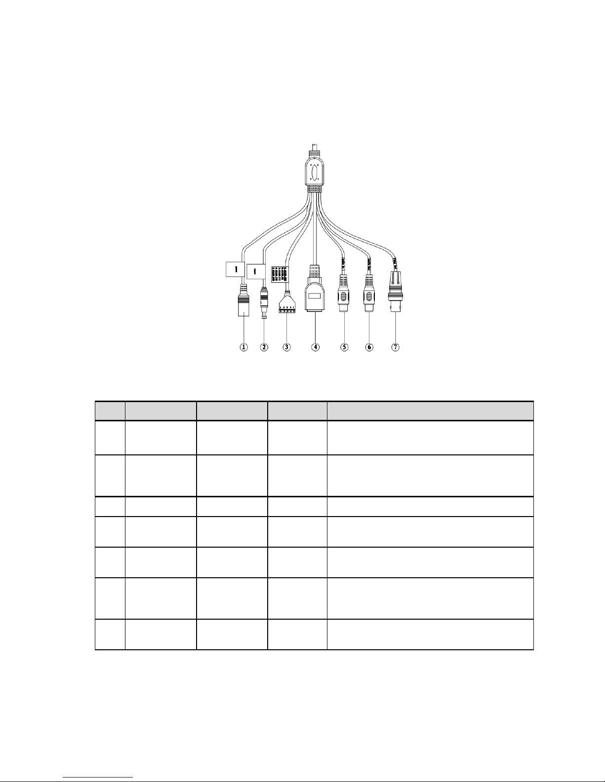
2.1 Multiple-function Combination Cable
You can refer to the following figure for multiple-function combination cable information. See Figure
2-1.
Figure 2-1 Multiple-function combination cable
Please refer to the following sheet for detailed information.
SN
Port Name
Function
Connection
Note
1
DC 12V/AC
24V
Power input
port
/
Power port. Input DC 12V/AC 24V (Please
use the provided conversion cable)
2
Reset
Reset port
/
Hardware reset function. Press it for 3 to 5
seconds; system hardware can restore
default setup.
3
I/O
I/O port
/
Connect to I/O port.
4
LAN
Network port
Ethernet
port
Connect to standard Ethernet cable.
5
AUDIO IN
Audio input
port
RCA
Input audio signal. It can receive the analog
audio signal from the pickup.
6
AUDIO OUT
Audio output
port
RCA
Output audio signal to the devices such as
the sound box.
7
VIDEO OUT
Video output
port
BNC
Output analog video signal. It can connect to
the TV monitor to view the vid
eo.
Please refer to the follow sheet for detailed I/O port information.
12
Port Name
SN
Name
Note
I/O Port
1
ALARM_COM
Alarm output public port.
2
ALARM_NO
Alarm output port. It is to output the alarm signal
to the alarm device.
NO: normal open al
arm output port.
It works with the ALARM_COM port.
3
ALARM_IN1
Alarm input port 1. It is to receive the on
-
off signal
from the external alarm source.
4
ALARM_IN2
Alarm input port 2. It is to receive the on
-
off signal
from the external alarm source.
5
GND
Ground port
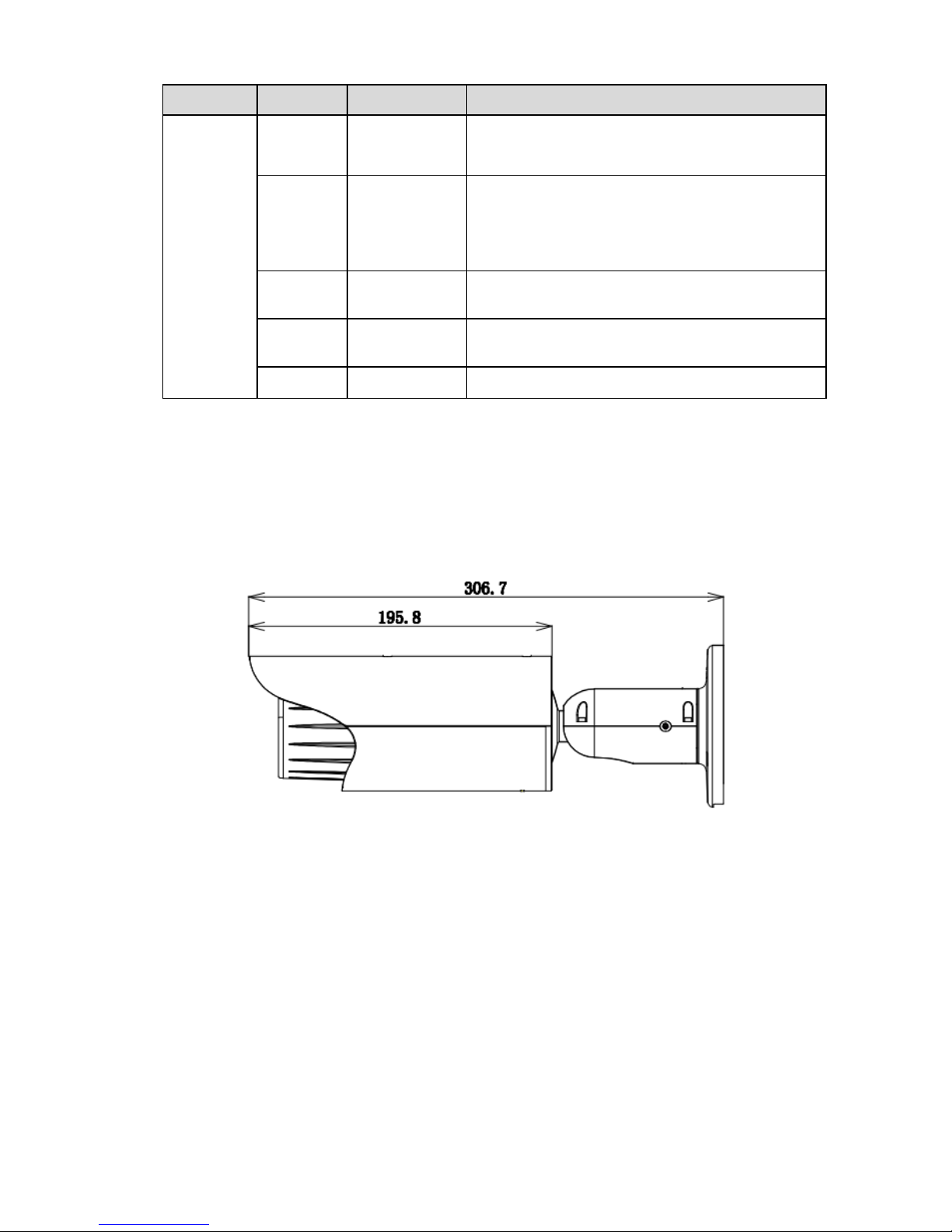
2.2 Framework and Dimension
Please note all frame and dimension illustrations provided in this chapter are for reference only,
and actual product may vary.
Please refer to Figure 2-2 or Figure 2-3 for dimension information according to the actual product. The
unit is mm. Please also see Figure 2-4.
Figure 2-2 Dimension illustration 1
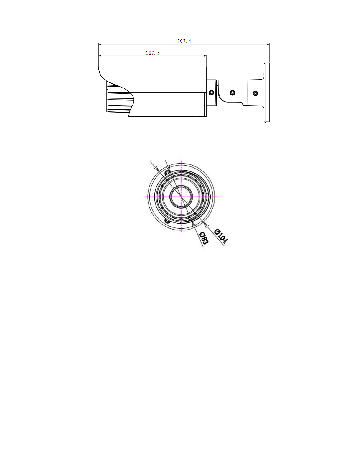
13
Figure 2-3 Dimension illustration 2
Figure 2-4 Dimension illustration 3
2.3 Bidirectional talk
2.3.1 Device-end to PC-end
Device Connection
Please connect the speaker or the MIC to the audio input port of the device. Then connect the
earphone to the audio output port of the PC.
Login the Web and then click the Audio button to enable the bidirectional talk function.
You can see the button becomes orange after you enabled the audio talk function.
Click Audio button again to stop the bidirectional talk function.
Listening Operation
At the device end, speak via the speaker or the pickup, and then you can get the audio from the
earphone or sound box at the pc-end.
2.3.2 PC-end to the Device-end
Device Connection
Connect the speaker or the MIC to the audio input port of the PC and then connect the earphone to
the audio output port of the device.
14
Login the Web and then click the Audio button to enable the bidirectional talk function.
You can see the button becomes orange after you enabled the audio talk function.
Click Audio button again to stop the bidirectional talk function.
Please note the listening operation is null during the bidirectional talk process.
Listening Operation
At the PC-end, speak via the speaker or the pickup, and then you can get the audio from the earphone
or sound box at the device-end.
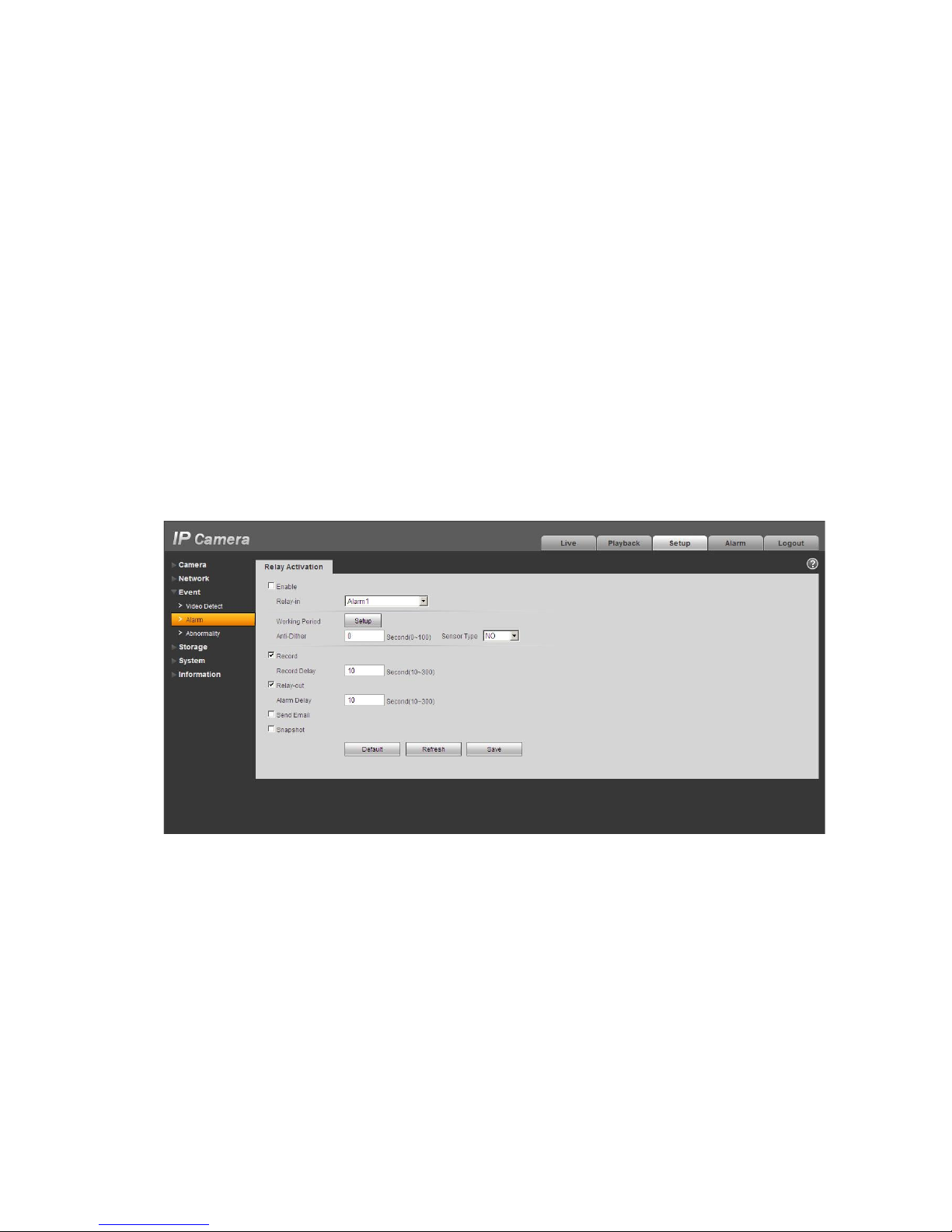
2.4 Alarm Setup
The alarm interface is shown as in Figure 2-5. Please follow the steps listed below for local alarm input
and output connection.
1) Connect the alarm input device to the alarm input port (No.3 pin or No.4 pin) of the I/O cable.
2) Connect the alarm output device to the alarm output port (No.2 pin) and alarm output public port
(No.1 pin). The alarm output port supports NO (normal open) alarm device only.
3) Open the Web, go to the Figure 2-5. Please set the alarm input 01 port for the first channel of the
I/O cable (No.3 pin). The alarm input 02 is for the 2nd channel of I/O cable (No.4 pin). Then you can
select the corresponding type (NO/NC.)
4) Set the WEB alarm output. The alarm output 01 is for the alarm output port of the device. It is the
No.2 pin of the I/O cable.
Figure 2-5 Alarm
Please refer to the following figure for alarm input information. See Figure 2-6.
Alarm input: When the input signal is idle or grounded, the device can collect the different statuses of
the alarm input port. When the input signal is connected to the 5V or is idle, the device collects the
logic “1”. When the input signal is grounded, the device collects the logic “0”.
This manual suits for next models
4
Table of contents


