Himel HAV SP Series User manual
Smart Pump User Guide
Himel Drives
Smart Pump – HAV SP Series
Variable Speed Drives for Asynchronous Motors
User Manual
07/2022
© 2022 HIMEL
Himel
www.himel.com
July 2022 www.himel.com

1
Preface
Thank you for purchasing the HAV-SP series drive developed and produced by Himel
HAV-SP drives are full-featured dedicated drives for parabolic load applications like pumps,
fans, and chillers. HAV-SP has a wide range of integrated features like multi-pump control, dry run
protection, sensor-less flow and energy calculation, pump cleaning, fire override mode, frost,
condensation and hammer effect protections to meet the needs of pump, fans and chillers for
modern buildings. HAV-SP also has functions like PID control, simple PLC, multi-speed control
and other functions to meet different process requirements.
Before using this drive, the users and relevant technicians shall read this manual carefully to
ensure that the drive can be properly installed and operated, so that the drive can perform its best
performance.
If there is any change to this user manual, please refer to the new version without notice.
High-performance Drive
User Manual
Version: V1.4

2
This product implements standards:
The design and production of this product refer to the latest national standards (GB or GB/T),
International Electrotechnical Commission Standards (IEC) and International System of Units (SI).
The technical parameters of the relevant parts can meet the requirements of national standards (GB
or GB/T) and International Electrotechnical Commission Standards (IEC). Main standards:
GB/T 12668.2-2002 Adjustable Speed Electrical Power Drive Systems - Part 2: General
Requirements - Rating Specifications for Low Voltage Adjustable Frequency AC Power Drive
Systems
GB 12668.3-2012 Adjustable Speed Electrical Power Drive Systems - Part 3: EMC
Requirements and Specific Test Methods
GB 12668.501-2013 Adjustable Speed Electrical Power Drive Systems - Part 5: Safety
Requirements - Electrical, Thermal and Energy
GB/T 2423.1-2008 Environmental Testing for Electric and Electronic Products - Part 1: Test
Methods Tests A: Cold
GB/T 2423.2-2008 Environmental Testing for Electric and Electronic Products - Part 2: Test
Methods Tests B: Dry Heat
GB/T 2423.3-2006 Environmental Testing - Part 2: Testing Method - Test Ca: Damp Test,
Steady State
GB/T 2423.4-2008 Environmental Testing for Electric and Electronic Products - Part 2: Test
method - Test Db: Damp heat, cyclic (12h+12h Cycle)
GB/T 2423.9-2006 Environmental Testing for Electric and Electronic Products - Part 9: Test
Methods Tests Cb: Constant damp heat for equipment
GB/T 2423.7-1995 Environmental Testing for Electric and Electronic Products - Part 7: Test
Methods Tests Ed: Free Fall
GB/T 2423.22-2012 Environmental Testing for Electric and Electronic Products - Part 2: Test
method - Test N: Change of Temperature
GB/T4798.1-2005 Environmental Conditions Existing in the Application of Electric and
Electronic Products - Storage
GB/T4798.2-2008 Environmental Conditions Existing in the Application of Electric and
Electronic Products - Transport
GB/T4798.3-2007 Environmental Conditions Existing in the Application of Electric and
Electronic Products - Work
3
Danger
The drive must be reliably grounded. If the drive is not reliably grounded, there may be
a potential danger of personal injury in the device.
Readers
This user manual is suitable for the following readers.
Drive installers, engineering technicians (electrical engineers, electrical operators, etc.),
designers, etc. Please ensure that this user manual reaches the end users.
Notational conventions in this manual
Caution: Moderate or minor injuries may occur due to failure to operate as required.
Danger: Deaths or serious injuries may occur due to failure to operate as required.

4
Table of Contents
Chapter I Product Specification and Ordering Instructions ............6
1.1 Drive series models ................................................. 6
1.2 Product appearance and installation dimensions .......................... 7
1.3 Dimensions of optional base .......................................... 9
1.4 Keypad size ....................................................... 9
1.5 Installation of remote keypad ........................................ 11
1.6 Name of each part of this series drives ................................. 12
1.7 Braking resistors .................................................. 13
Chapter II Installation and Wiring of Drive .........................16
2.1 Drive installation environment ....................................... 16
2.2. Removal and installation of drive panel ............................... 20
2.3 Wiring of main circuit terminals ......................................22
2.4 Control circuit configuration and wiring ............................... 26
Chapter III Operation Instructions of Drive .........................32
3.1 Key function description ............................................ 32
3.2 Keypad operation methods .......................................... 32
Chapter IV Function Parameter Table .................................35
4.1 Function parameter table ............................................35
4.2 Monitoring parameter group U0 ...................................... 97
4.3 Fault record parameter group U1 .................................... 100
4.4 Fault code summary table .......................................... 101
Chapter V Basic Operation Instructions .............................102
5.1 Start operation mode .............................................. 102
5.2 Start-stop control ................................................. 105
5.3 Frequency setting .................................................108
5.4 Analog input .................................................... 110
5.5 Analog output ................................................... 112

5
5.6 Digital input ..................................................... 114
5.7 Digital output .................................................... 119
5.8 Simple PLC ..................................................... 123
5.9 Multistage speed operation ......................................... 127
5.10 PID control .....................................................131
5.11 Multi-pump control ...........................................136
5.12 Troubleshooting .................................................144
Appendix I Communication Protocol ..................................151
Appendix Ⅱ Multi-pump control expansion card applications .........156
6.1 Multi-pump control expansion card installation instructions .............. 156
6.2 Multi-pump control expansion card terminal function description .......... 156
6.3 Fault countermeasures and exception handling ......................... 157

6
Chapter I Product Specification and Ordering Instructions
1.1 Drive series models
The input voltage range of this drive is 380V-440VAC and 220V-240V. The adaptive motor
power range is 2.2 kW ~ 160 kW. The models of this series drives are shown in Table 1-1.
Table 1-1 Drive Models
Drive model
Rated capacity
(kVA)
Rated output
current
(A)
Adaptable motor
(kW)
HAV-SP-4T0022P
3.7
5.0
2.2
HAV-SP-4T0030P
4.9
7.5
3.0
HAV-SP-4T0040P
7.5
8.8
4.0
HAV-SP-4T0055P
8.5
13
5.5
HAV-SP-4T0075P
11
17
7.5
HAV-SP-4T0110P
17
25
11
HAV-SP-4T0150P
21
32
15
HAV-SP-4T0185P
24
37
18.5
HAV-SP-4T0220P
30
45
22
HAV-SP-4T0300P
40
60
30
HAV-SP-4T0370P
50
75
37
HAV-SP-4T0450P
60
90
45
HAV-SP-4T0550P
72
110
55
HAV-SP-4T0750P
100
157
75
HAV-SP-4T0900P
116
180
90
HAV-SP-4T1100P
138
214
110
HAV-SP-4T1320P
167
256
132
HAV-SP-4T1600P
200
307
160
HAV-SP-2T0022P
3.7
10.08
2.2
HAV-SP-2T0030P
4.9
11.5
3.0
Chapter I Product Specification and Ordering Instructions
7
Drive model
Rated capacity
(kVA)
Rated output
current
(A)
Adaptable motor
(kW)
HAV-SP-2T0040P
7.5
16.2
4.0
HAV-SP-2T0055P
8.5
20.3
5.5
HAV-SP-2T0075P
11
26.7
7.5
HAV-SP-2T0110P
17
39
11
HAV-SP-2T0150P
21
52.5
15
HAV-SP-2T0185P
24
62.4
18.5
HAV-SP-2T0220P
30
73.6
22
HAV-SP-2T0300P
40
98.7
30
HAV-SP-2T0370P
50
121
37
HAV-SP-2T0450P
60
147
45
Note: If you need models of other power ranges, please consult the manufacturer before
ordering!
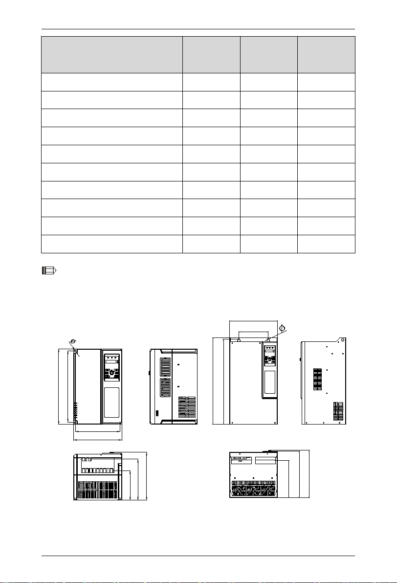
1.2 Product appearance and installation dimensions
W1
W
H1
H
D2
D1
D
W1
W
H1
H
D
D2
D1
(a) A specification (b) B specification

8
Table 1-2 Drive Appearance and Installation Series Dimensions (Unit: mm)
Drive Model
W
W1
H
H1
D
D1
D2
Mounting hole
diameter
(Φ)
Reference
picture
HAV-SP-4T0022P
120
109
215
204
163
133
85
5.5
(a)
HAV-SP-4T0030P
HAV-SP-4T0040P
HAV-SP-4T0055P
HAV-SP-4T0075P
HAV-SP-2T0022P
HAV-SP-2T0030P
HAV-SP-2T0040P
HAV-SP-4T0110P
150
138
259
248
181
150
104
5.5
(a)
HAV-SP-4T0150P
HAV-SP-2T0055P
HAV-SP-2T0075P
HAV-SP-4T0185P
205
188
322
305
215
176
130
6.5
(a)
HAV-SP-4T0220P
HAV-SP-2T0110P
HAV-SP-4T0300P
235
218
370
350
235
200
146
7
(a)
HAV-SP-4T0370P
HAV-SP-2T0150P
HAV-SP-2T0185P
HAV-SP-4T0450P
305
200
490
470
275
270
211
10
(b)
HAV-SP-4T0550P
HAV-SP-2T0220P
HAV-SP-2T0300P
HAV-SP-4T0750P
320
197
560
543
307
302
240
10
(b)
HAV-SP-4T0900P
HAV-SP-4T1100P
HAV-SP-2T0370P
HAV-SP-2T0450P
HAV-SP-4T1320P
355
240
678
659
319
314
261
11
(b)
HAV-SP-4T1600P
Note: 1. The base of HAV-SP-4T0450P~HAV-SP-4T1600P and HAV-SP-2T0220P~HAV-SP-2T0450P
are optional.
Chapter I Product Specification and Ordering Instructions
9
1.3 Dimensions of optional base
W
H-300mm
D
Note: The dimensions of the base in W and D directions are consistent with the corresponding
model, as shown in Table 1-2, and the H dimension is fixed at 300mm.
Table 1-3 Base Matching Table
Base jacking model
Adaptable models
HAV-XS-4T0370DZ
HAV-SP-4T0450P~HAV-SP-4T0550P
HAV-SP-2T0220P~HAV-SP-2T0300P
HAV-XS-4T0750DZ
HAV-SP-4T0750P~HAV-SP-4T1100P
HAV-SP-2T0370P~HAV-SP-2T0450P
HAV-XS-4T1100DZ
HAV-SP-4T1320P~HAV-SP-4T1600P
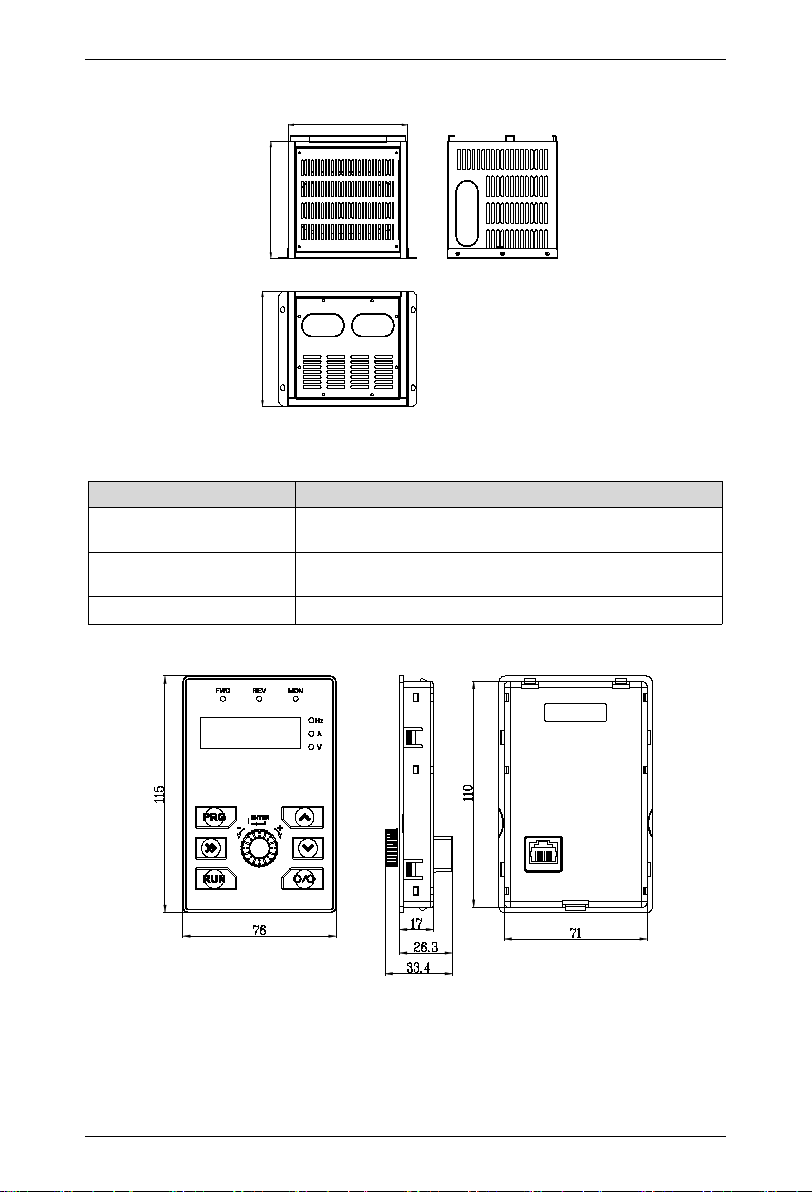
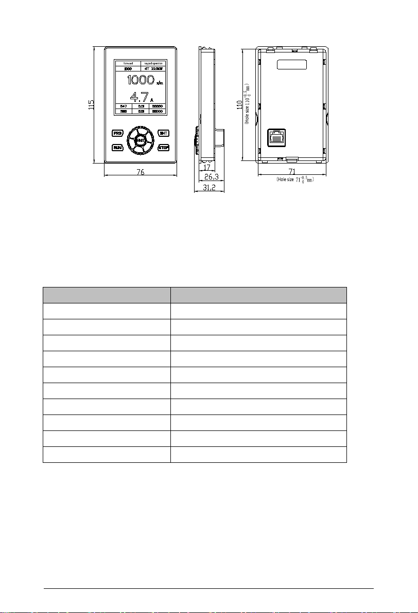
1.4 Keypad size
Figure 1-1 Keypad HAV-SP-LKD Size
10
Figure 1-2 Keypad HAV-SP-LCD Size
Table 1-4 Datasheet of HAV-SP-LCD
Item
Description
Display screen size
55*55mm
Display resolution
160*160
Display mode
Blue screen
Keypad interface
RJ45 interface
USB interface
Micro USB
Humidity
Less than 90%RH, no condensation
Vibration
Less than 5.9m/s2
Environment temperature
-10°C~+50°C
Storage temperature
-40℃~+60℃
Protection class
IP20
Chapter I Product Specification and Ordering Instructions
11
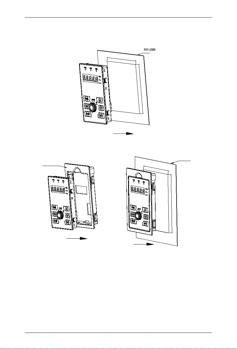
1.5 Installation of remote keypad
The remote keypad can be installed in two ways, one is directly installed on an iron plate, and the
other is installed on an optional keypad tray.
Opening size71.5mm±0.3mm
Opening size111.0mm±0.3mm
When the remote keypad is installed on an iron plate, the installation process is shown in the figure.
Press down the keypad in the direction of the arrow until a "click” sound is heard.
Keypad tray
Iron plate
Opening size 81±0.3mm
Opening size 130±0.3mm
When the remote keypad is installed on an optional keypad tray, the installation process is
shown in the figure. Place the keypad into the tray in the direction of the arrow, and press down the
entire keypad in the direction of the arrow, until a "click” sound is heard.
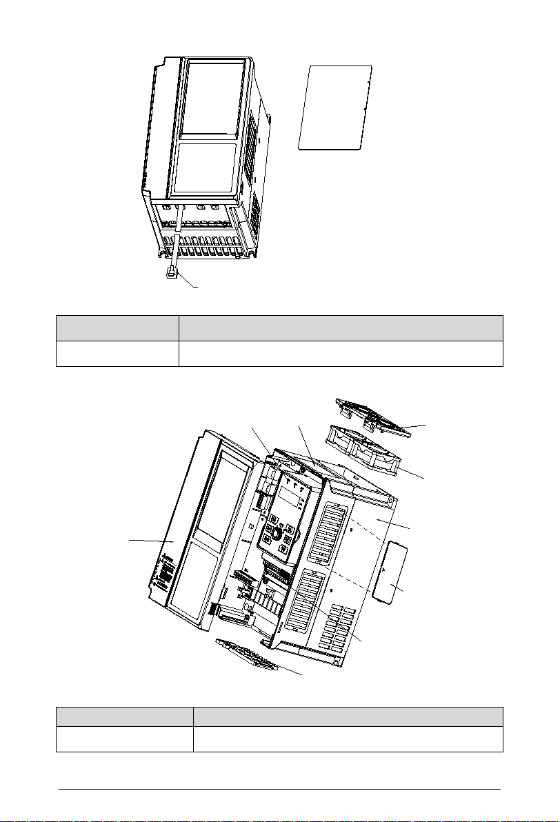
1.5.1 Dust-proof sticker for optional parts (schematic diagram of outlet position of outgoing
keypad line)
12
Panel dustproof sticker
Remote control of
local keypad Remote control of
local keypad
External keypad line
Table 1-5 Dustproof Sticker Model
Dustproof sticker model
Adaptable models
HAV-XS-FCT
HAV-SP-4T0022P~HAV-SP-4T1600P
HAV-SP-2T0022P~HAV-SP-2T0450P
1.6 Name of each part of this series drives
Housing
Fan
Fan
cover
Wire slot
plate
Shell
Keypad
Control
terminal
Drive's
nameplate
Dustproof
cover plate
(optional)
Table 1-6 Dustproof Cover Plate Model
Dustproof cover plate model
Adaptable models
HAV-XS-4T0220 (black)
HAV-SP-4T0022P~HAV-SP-4T0370P
HAV-SP-2T0022P~HAV-SP-2T0185P

Chapter I Product Specification and Ordering Instructions
13
1.7 Braking resistors
Please select energy consumption braking resistors according to Table 1-6. The wiring of the
braking resistors is shown in Figure 1-2.
Figure 1-3 Drive and Braking Assembly Wiring Diagram
Note:
1. The power derating of the braking resistor shall not exceed 30%, otherwise there is a risk of
fire.
2. For braking standard products of 37kW and below, the built-in braking unit can be used; for
braking those of 45kW and above, an external braking unit needs to be added.
3. The wiring length of the braking resistor shall be less than 5m. During the energy
consumption braking process, the braking resistor will cause temperature rise due to energy
consumption. During installation, pay attention to safety protection and sound ventilation.
The braking resistor resistance and the power are selected according to the actual situation.
The greater the system inertia, the shorter the deceleration time required, the more frequent the
braking, the greater the power required by the braking resistor and the smaller the resistance
required. Table 1-6 is recommended based on general applications.
Table 1-7 Braking Resistor Selection Table(380V)
Specification
Suitable motor
power (kW)
Braking resistor
recommendation
Resistance (Ω)
Braking resistor
recommendation
Power (W)
HAV-SP-4T0022P
2.2
200
100
HAV-SP-4T0030P
3.0
200
200
HAV-SP-4T0040P
4.0
200
300
HAV-SP-4T0055P
5.5
200
300
HAV-SP-4T0075P
7.5
≥80
750
HAV-SP-4T0110P
11
≥50
1100
HAV-SP-4T0150P
15
≥50
1500
HAV-SP-4T0185P
18.5
≥45
1800

14
Specification
Suitable motor
power (kW)
Braking resistor
recommendation
Resistance (Ω)
Braking resistor
recommendation
Power (W)
HAV-SP-4T0220P
22
≥45
2200
HAV-SP-4T0300P
30
≥24
3000
HAV-SP-4T0370P
37
≥24
3000
Table 1-8 Braking Resistor Selection Table(220V)
Specification
Suitable motor
power (kW)
Braking resistor
recommendation
Resistance (Ω)
Braking resistor
recommendation
Power (W)
HAV-SP-2T0022P
2.2
≥100
200
HAV-SP-2T0030P
3.0
≥75
300
HAV-SP-2T0040P
4.0
≥75
300
HAV-SP-2T0055P
5.5
≥50
400
HAV-SP-2T0075P
7.5
≥45
750
HAV-SP-2T0110P
11
≥30
1100
HAV-SP-2T0150P
15
≥30
1100
HAV-SP-2T0185P
18.5
≥18
1800

Chapter I Product Specification and Ordering Instructions
15
1.8 Accessary of HAV-SP
If you need the accessories as follow, please specify when ordering.
Name
Reference
Short Description
Applicable Product
Dust cover
HAV-SP-FCB
Prevent dust from entering
the drive
HAV-SP-4T0022P~H
AV-SP-4T0370P
HAV-SP-2T0022P~H
AV-SP-2T0185P
Keypad tray
HAV-SP-JPT
Use when an external
keypad is installed
All series
LCD Keypad
HAV-SP-LCD
LCD keypad
All series
Simple IO
expansion card
HAV-XS-IO-3DI-R
Expand 3 DI, 1 relay
HAV-SP-4T0022P~H
AV-SP-4T1600P
HAV-SP-2T0022P~H
AV-SP-2T0450P
IO expansion card
HAVSPIO3DI3R
Expand 3 DI, 3 relay
HAV-SP-4T0022P~H
AV-SP-4T1600P
HAV-SP-2T0022P~H
AV-SP-2T0450P
Mounting bracket
HAV-XS-4T*
For embedded installation
of drive
*:For detailed model
and power matching,
please refer to Table
2-2
Mounting base
HAV-XS-4T*
Used for cabinet
installation
*:For detailed model
and power matching,
please refer to Table
1-4
Dustproof sticker
HAV-SP-FCT
Use when an external
keypad is installed
All series
Chapter II Installation and Wiring of Drive
16
Chapter II Installation and Wiring of Drive
2.1 Drive installation environment
2.1.1 Installation environment requirements
(1) Install in a well-ventilated indoor place. The ambient temperature is required to be within the
range of -10ºC-40ºC. If the temperature exceeds 40ºC, external forced cooling or derating is
required.
(2) Avoid installing in places with direct sunlight, dusty, floating fibers and metal powder.
(3) Do not install in places with corrosive or explosive gases.
(4) The humidity is required to be lower than 90%RH, without condensation of water droplets.
(5) Install in places where the plane fixed vibration is less than 5.9 m/s2.
(6) Try to keep away from electromagnetic interference sources and other electronic instruments
and equipment that are sensitive to electromagnetic interference.
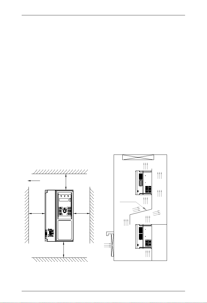
2.1.2 Installation direction and space
(1) Generally, vertical installation shall be adopted.
(2) Minimum installation intervals and distances are shown in Figure 2-1.
(3) When multiple drives are installed up and down, the baffle applied in the middle is shown in
Figure 2-2.
B
Fan exhaust
B
AA
Deflector
DriveDrive
Figure 2-1 Installation Diagram Figure 2-2 Installation Diagram of Multiple Drives
Chapter II Installation and Wiring of Drive
17
Table 2-1 Installation Space Requirements
Drive model
Installation space (mm)
A
B
HAV-SP-4T0022P~HAV-SP-4T0550P
HAV-SP-2T0022P~HAV-SP-2T0300P
≥50
≥100
HAV-SP-4T0750P~HAV-SP-4T1600P
HAV-SP-2T0370P~HAV-SP-4T0450P
≥50
≥200
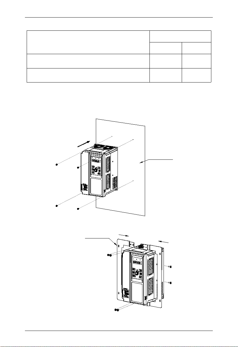
2.1.3 Mechanical installation methods and steps
According to different power levels, HAV-SP series has two structures namely plastic and
sheet metal. According to different installation applications, there are two installation methods:
Wall-mounted and embedded.
1. Wall mounting of plastic structure
Install from front
Control cabinet
mounting plate
Figure 2-3 Wall-mounted Installation Diagram of Plastic Structure
2. Embedded installation of plastic structure
Embedded installation support
Figure 2-4 Embedded Support Installation Diagram of Plastic Structure

Chapter II Installation and Wiring of Drive
18
Install from front
Control cabinet
mounting plate
Figure 2-5 Embedded Installation Diagram of Plastic Structure
3. Wall mounting of sheet metal structure
Hoisting
hole
Control cabinet
mounting plate
Install from front of
control cabinet
Fix with 4 screws
Figure 2-6 Wall-mounted Installation Diagram of Sheet Metal Structure
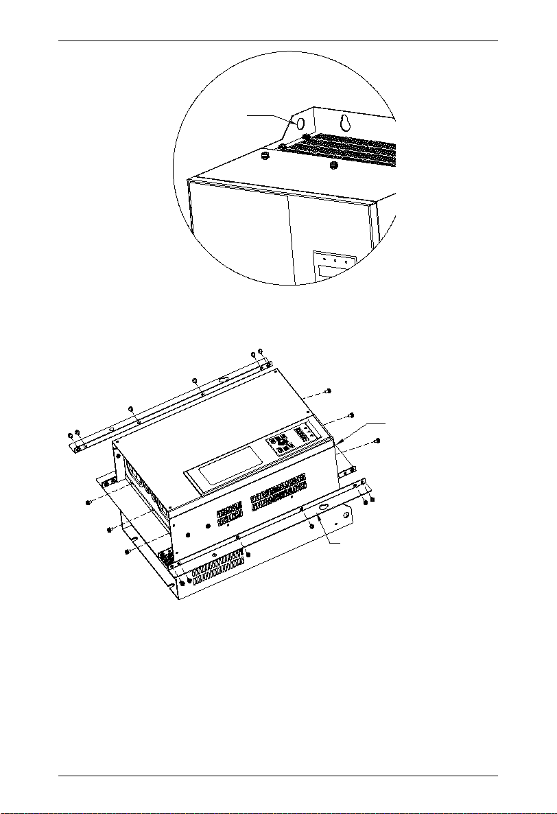
Chapter II Installation and Wiring of Drive
19
Hoisting hole
Figure 2-7 Hoisting Diagram of Sheet Metal Structure
4. Embedded installation of sheet metal structure
Embedded installation
support
Embedded installation support
Figure 2-8 External Support Diagram of Sheet Metal Structure
This manual suits for next models
20
Table of contents
Popular Water Pump manuals by other brands

Pentair
Pentair STA-RITE D Series owner's manual

Grundfos
Grundfos UP 15 series instructions

Ferro
Ferro GPA II Installation and operation manual

Pentair
Pentair Hypro 9200 Series Installation and operation manual

Zoeller
Zoeller QWIK JON CHOICE 200 installation instructions

Linde
Linde HPR-01 D ADJUSTMENT PROCEDURE


