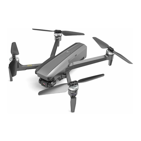
HiRO Game of Drones Manual


Congratulations on your purchase of the Game of Drones® Hiro Build-It-Yourself kit.
When you’re done, you’ll have your very own Hiro drone ready to bind to a transmit-
ter. We designed this kit to be easy to use, fun, and educational. When you’ve com-
pleted the Game of Drones® Hiro Build-It-Yourself kit, you will not only have a drone
to y, you’ll also know more about how drones work. This may be your rst drone you
build, but don’t let it be your last. There’s a lot of building out there, and you’ve just
taken your rst step.
Content list
Your Game of Drones® Hiro Build-It-Your-
self kit should include the following:
One Game of Drones® Hiro airframe;
Five lengths of plastic trim (four longer, one
shorter);
Cable ties;
Four wood motor mounts;
One KK 2.1 HC Multi-Rotor Control Board
with Programmer;
Two clockwise (CW) RCMC 2212 1000Kv V2
motors;
Two counterclockwise (CCW) RCMC 2212
1000Kv V2 motors;
16 small black screws;
5 servo wires;
1 grey ribbon cable;
Four RCMC 30Amp SimonK Firmware Elec-
tronic Speed Controllers (ESCs);
One power distribution board;
Four tabs of mounting tape;
Four propellers;
Four sets of propeller adapters;
One frame cap
Tools you’ll need:
Phillips screwdriver
Allen wrenches size 2 mm, 2.5 mm
Small-nose pliers
Wire cutters
Scotch or masking tape
Pliers or a ½-inch mini rachet
Pen
Other parts you’ll need:
RC transmitter
Receiver compatible with your transmitter
A 2200mAh 3S 30C LiPo battery with an
XT60 plug


Laying out your components
Estimated time to complete: 5 minutes
Remove the airframe from the box and separate the two sides. Lay them out and
become familiar with them.
The side with the hole in the center is the “top shell.” The “front” of your drone is
adorned with the “Game of Drones” sticker. Keep that in mind when you’re building.
The side without the hole is the “bottom shell.” The bottom shell is symmetrical, so
you don’t need to worry about a front or back.
Now, take your components out of the box and verify you have all the parts and piec-
es. If you nd something missing, contact us immediately.
Ready to build a drone?
Attaching motors to your frame
Estimated time to complete: 25 minutes
Start your drone-building odyssey by attaching the motors to your frame. You have
four motors and four arms. One motor is attached to each arm.

First take a moment to become familiar with your arms. Not the ones on your body;
the ones on your frame. Arm 1 is a friend, and you and it will spend a lot of time to-
gether. After you’ve identied Arm 1 through 4, use a small piece of tape and a pen
to number your arms so you can easily nd them later.
Pull out the box of two motors with black cap screws, the box of two motors with
green cap screws, the four wood motor mount disks, and the baggie of small black
screws.
Using your allen wrench, attach the two counterclockwise (green-capped) motors to
Arm 1 and Arm 3, and the two clockwise (black capped) motors to Arm 2 and Arm 4.

Starting with your old friend, Arm 1, place one of the wood motor mount disks inside the
frame and make sure all the holes on the disk align with the holes on the frame. The holes
are not in a perfect square, so if they don’t align, turn the mount 90 degrees and look again.
Eventually, you will get the mount so the holes all line up. Then use one of the small black
screws to secure the mount to the frame, screwing in until just the tip of the screw can be
seen coming through the top of the frame.
This step is a bit ddly and can be challenging the rst time you do it, but once you get the
hang, the other three will go on fairly quickly.
NOTE: DO NOT USE LOCTITE OR ANY SCREW
ADHESIVE ON YOUR SCREWS. We promise the
Screw Gods will not smite you and send your
motor inging o your frame if you don’t.
The motor mount was specially designed to
grip your screws and help prevent the need
for Loctite. If you do use Loctite, however, the
Frame Gods, who are division of the Plastics
and Chemistry Gods, will reign down cracks
on your frame. (That’s our way of saying the
chemicals in Loctite interact badly with the
plastics in the frame. So don’t do it.)

Then get a CCW motor (double check you’ve got the right one!) and align it so its wires
are pointed toward the center of the frame. Then line up the screw hole in the bottom of
the motor with the tip of the screw sticking out of your frame. Screw in the motor until it
is rm, but not so rm you can’t swivel the motor a bit to get the other three holes to line
up. Then screw in the other three screws.
Once you’ve got all four screws in
place, go back and tighten all four
screws rmly but not too tightly.
The head of the screw should be
ush with the wood mount. DO
NOT OVERTIGHTEN. If you screw
in as hard as possible, you’ll drive
the screw into the motor’s internal
parts and permanently damage it.
If you’re sinking the screw into the
wood, you’ve gone too far. Just a
rm t is good.

Do this for all four motors, making sure your CCW motors go on Arm 1 and Arm 3 and your
CW motors go on Arm 2 and Arm 4.
Now string all the wires coming out of the motors through the little slot in the frame next to
the motor. It’s easiest to string these through one at a time rather than all three at once.

Mounting your Control Board to your Power Distribution Board
Estimated time to complete: 10 minutes
Set your frame aside and get out your KK 2.1 Control Board (The one that has a “Multi-Rotor
Control Board” sticker) and your Power Distribution Board. Inside the Control Board box
you’ll nd four long black bolts with little silver nuts. Now take a moment to get familiar with
Grab your Power Distribution Board and you’ll
see a thick red and black wire with a yellow tip
coming o of it. This is your power cable, which
will connect to your battery. You’ll need to make
your Power Distribution Board as at as possible,
so split the red and black wires apart and orient
the wires so the black wire is to the left of the
plugs closest to where it attaches to the board
and the red wire is to the left of the plugs closest
to where that wire is attached.
NOTE: If you squint, it looks like a little heart.
your Control Board. On the bottom of its case
you’ll see a small arrow and the word “forward.”
On the top is a label that reads “Multi-Rotor
Control Board.”
Place your Control Board on the table with the
label-side up and the forward arrow pointing
away from you. You’ll know you’re in the right
position if the words on the label are right-side
up. If they’re upside down, spin it around. If you
are seeing the arrow, ip it over.

Attaching your ESCs
Estimated time to complete: 20 minutes
Now you’re ready to plug in and test your
Electronic Speed Controllers (ESCs). Pull your
four RCMC 30Amp SimonK Firmware ESCs
out of their silver pouches. One end has three
wires (red, blue and black). These wires will
plug into your motors. The other end has two
wires (red and black) and a thin cable called
a “servo wire.” This end will plug into your
Control Board and your Power Distribution
Board.
NOTE: Don’t mess these next steps up or you
will burn up your ESC.
Now ip your Power Distribution Board over so the black squishy side is up, and lay it over
your KK 2.1 Control Board, sandwiching the power cables between the two boards. The
power cables and the yellow tip should be pointing away from you (pointing in the same
direction as the “forward” arrow on your Control Board). Insert the long bolts into the four
corner holes of the Power Distribution Board and through the four corner holes of the
Control Board. Secure the bolts with the silver nuts, making sure they are rm. A few turns
with your small-nose pliers should do the trick. Don’t get too enthusiastic about it, though,
or you may crack the Control or Power Distribution boards.
Now ip your boards over and make sure the “forward” arrow is
pointing in between your power cables.

Plug the red wire from the end with the servo wire
into your Power Distribution Board. You can use
any of the plugs on your Power Distribution Board
EXCEPT the ones on the back (opposite of the
forward arrow on your Control Board).
Make sure the red wire goes into a red-colored
plug on your Power Distribution Board, and plug
the black wire into a black-colored plug. If you re-
verse this, you will burn up your ESC, so be careful
and double-check your work.
NOTE: Any spare plugs you don’t use can be used
at a later time if you ever want to customize your
Hiro with lights, FPV cameras, camera gimbals, or
other components.
Do this for all four ESCs. It doesn’t matter which
set of black and red plugs you use, but you’ll want
to space them out a bit. We recommend plugging
one ESC into the right side of the Power Distribu-
tion Board, one into the left side, and two into the
front. Remember: don’t plug anything into the
back plugs.
Now grab your bottom shell and lay out your four ESCs in the arms and the Power Distribution
Board/Control Board into the center to test your layout.
Position the Distribution Board/Control Board in the center part of the frame, with the black,
squishy side down and the forward arrow up. The forward arrow and the battery cable should
be pointing between Arm 1 and Arm 2. Slide the board to the back of the frame so the arrow
mark sits right on top of the middle of your
frame.

With the boards in place, the ESCs
should arrange easily about ¼ of
the way up each of the arms, more
or less. It’s okay to have a little
extra wire, but if you’re nding any
wires on an ESC are too short or
too long, you might want to move
the wires to another plug on your
Power Distribution Board to give
you more or less slack.
Why is this important? Because the computer chip important to navigation is located right
below where the arrow is on the case. Putting that chip in the center of the drone makes a
big dierence in how it ies.
Now take a good look at what you’ve got and you’ll see why you can’t use the back plugs on
your board. They should be right up against the back of the frame and fairly unusable.

Now look at your KK 2.1 Control Board. On the back side, you’ll see a plug called “Program-
ming Port.” Grab the at, grey ribbon cable from the KK 2.1 Control Board box and plug one
of the ends (doesn’t matter which) into the Programming Port. Give it a good push to make
sure it’s rmly seated. Leave the other end free for the moment, as this will be the cable
you’ll use to connect your Programmer to the board when you’re tuning it. Just plug in the
cable and leave it there for convenience.
Now grab your double-sided tape tabs and attach them to the four corners of the the
squishy side of the Distribution Board/Control Board, then stick it to your frame in the posi-
tion you just tested out.
Attaching the Servos
Estimated time to complete: 5 minutes
Now you’re ready to attach all those servo wires coming out of your ESCs. Take a look at your
Control Board. On the right side, you’ll see a bunch of “Out” pins numbered 1 through 8.
Start with the ESC you plan to put in your new best friend, Arm 1. Holding the connector on
the servo wire with the white wire up, plug the servo wire into the pins on the right side of
your Control Board in position 1. Do yourself a favor and put a small piece of tape on this ESC
so you can later identify it as ESC 1. You will need to know this later.
Now that ESC 1 is all plugged in, place it back in Arm 1.

Now do the same with ESC 2 (the one that will go in Arm 2), plugging it into to position 2 on
your Control Board. Follow up with ESC 3 and ESC 4 into positions 3 and 4.

A Little About Receivers
There’s a lot of technical talk, here, but we’ll try to make it as understandable as possible.
This is just a bit of background and shouldn’t be used as your instructions. You denitely
want to use the instructions that came with your transmitter/receiver set to do the actual
installation properly.
There are, for the most part, two kinds of receivers: “PWM-based” and “PPM-based,” which
is sometimes called “CPPM.” These are the two languages your transmitter and receiver use.
You need to know which type your transmitter/receiver set uses before you plug in.
Attaching Your Receiver
Estimated time to complete: 15 minutes
Now is the time you’ll plug in your receiver. This is part of a matched set with your transmit-
ter (the thing in your hands you use to steer your drone). Because there’s a lot of transmitters
out there with varying degrees of complexity and prices, we’ve left this decision up to you.
You’ll connect your receiver to your KK 2.1 Control Board using servo cables we’ve included
with your kit. We’ve given you three cables, but you may only need one.
Refer to the manual for your transmitter/receiver package on how to hook it up to your
Control Board.

If you use a PWM-based receiver, it’s pretty straightforward. Look at the wires coming from
the receiver and match them with the plugs on the left side of your Control Board. “AIL” will
go to the “AIL” plug, “ELE” will go to the “ELE” plug, “THR” to “THR,” and “RUDD” to “RUDD.”
(Side note: Those stand for “aileron,” “elevator,” “throttle,” and “rudder.”)
With a PWM-based receiver, for those four channels you’ll plug the AIL servo into the AIL
channel, the RUDD to the RUDD channel, the ELE to ELE, and the THR to THR.
On your receiver, there will be a fth channel that’s used for the self-leveling mode. This
could be called “AUX,” “Gear,” “Channel 5,” or some other name, depending on your
receiver’s manufacturer. You need to refer to your receiver’s manual to know what it’s
named. This allows you to switch between manual-leveling mode and self-leveling mode
using a switch on your transmitter. There are other methods of doing this switching, but
we highly recommend you do your switching through your transmitter by plugging in your
“AUX” to the AUX channel.
If you use a PPM-based receiver, all information for AIL, ELE, THR, RUDD, and AUX come
through one servo cable. Plug the PPM output wire from the receiver into the “AIL” plug.
Keep in mind, though, if you use a PPM receiver you will have to make a nal adjustment
in the end of the programming of your Control Board, as the KK 2.1 is set for PWM-based
receivers by default.
As we said, this section is NOT to be used as your instructions for connecting your receiver.
Don’t rely upon it. Instead, make sure to use the instructions for your receiver for connecting
it properly.
If you can’t nd installation instructions for your receiver, you can nd links to the most
popular receivers on our website at www.GameofDrones.com/diymanuals.

Plugging In Your Motors
Estimated time to complete: 5 minutes
Grab the top shell with your motors attached. You’ll notice the wires from the motors are
colored red, black, and yellow and the wires from your ESC are colored red, black, and blue.
For all your motors, connect them to your ESCs by plugging them together. Don’t worry
about being in a particular order. That will come later.
Congratulations! You’re almost there!
Getting Ready to Test Your Motors
Estimated time to complete: 5 minutes
Before you close up the hood, you want to make sure you haven’t made any mistakes and
everything is spinning properly.
First go through all your connections and make sure you’ve done them correctly, especially
the power cables between your ESCs and your Power Distribution Board. If you’ve mixed up
your wiring, you may fry some electronics, so double check it well.
Now, if you’ve jumped ahead and attached your propellers, back it up, cowboy. Remove
those props. You are about to check your motor rotation, and having the props on now can
be very dangerous. Never test a motor with propellers attached unless you like the sight of
your own blood and don’t really care about losing things like ngers, noses, or lips. Props
are the last thing you’ll put on once you know your drone is working properly. Don’t be a
statistic.

Press the rightmost key (the “Menu” button)
on your Programmer. Now use the “Down”
key to scroll to “Mode Settings.” Then hit the
rightmost button again (which is now labeled
“Enter”).
Press the “Next” button and scroll to “CPPM
Enabled,” and press the rightmost key again
(now, it’s the “Change” key) until you see on
the screen that the CPPM Enabled setting is
“Yes.”
Now press the leftmost “Back” button once,
which will take you back to the main menu.
If You Are Using a PPM-Based Transmitter/Receiver
This section is only for those who are using a PPM-based receiver. If you are using a PWM-based
receiver, skip this section. The KK 2.1 is set by default to use PWM, so no extra steps are needed.
First, check and double check your connections before applying power, especially your con-
nections of your ESCs. Make absolutely sure you have everything plugged in correctly.
Get out your KK 2.1 Programmer and plug it into the at grey ribbon cable you attached to
the Programming Port. The cable can only be attached in one direction, so you won’t be
able to attach it the wrong way. Push it in well, as it needs to be well seated.
Turn on your transmitter and plug in a
charged battery to the yellow battery plug
coming out of your Power Distribution Board.

Final Test Prep
Now you’ll bind your transmitter to your receiver. Check your transmitter’s manual on how
to do this.
For more information about manuals for the most popular transmitters and receivers, visit
www.GameofDrones.com/DIYmanuals
Setting Your Motor Layout
Estimated time to complete: 5 minutes
Now you will tell the ight board how your motors are laid out so it will y the right way.
Connect your Programmer to the ribbon cable and plug in the battery to the power cable.
The screen on your programmer will display that you are in “safe” mode. Press the rightmost
“menu” button, and using the “Down” button, scroll down to “Load Motor Layout” and press
the enter button.
Using the “Down” button, scroll down to “Quadcopter X mode” and press “Enter.” Be careful
to not choose the “Quadcopter + mode,” as this is a dierent layout. When it asks “Are you
sure?” choose “Yes.” You will then see a display of your motor layout, with Motors 1, 2, 3, 4 in
their proper places.
Press the “Back” key until you are back on the “Safe” screen.

If you aren’t getting these responses, or the responses are reversed (it says “left” when
you move the sticks “right,“ forward” when you move the sticks “back,” or the values
between left and right are disproportionate to each other) check your transmitter’s manual
to troubleshoot your channels or invert your signals on your transmitter. The instruction
manual for your transmitter should tell you how to do that.
When all signals are correct, press the “Back” button to return main menu, and unplug your
battery.
Testing Your Signal
Estimated time to complete: 5 minutes
Turn on your transmitter and plug in your battery. You’ll hear a few beeps, and the Control
Board and your receiver will power up.
Now, let’s make sure your Control Board is getting signal from your transmitter.
Plug in your programmer if it isn’t already plugged in and press the rightmost key on your
Programmer to enter the “Menu.” Use the “Down” button to scroll to “Receiver Test,” and hit
the rightmost “Enter” key. You’ll see values from the inputs of your receiver. Move the sticks
on your transmitter and you should see those values change.
Moving your right stick up and down should change the value for “Elevator,” while moving
it left and right should change “Aileron.” Moving the left stick up and down should change
“Throttle,” and left and right should change “Rudder.”
