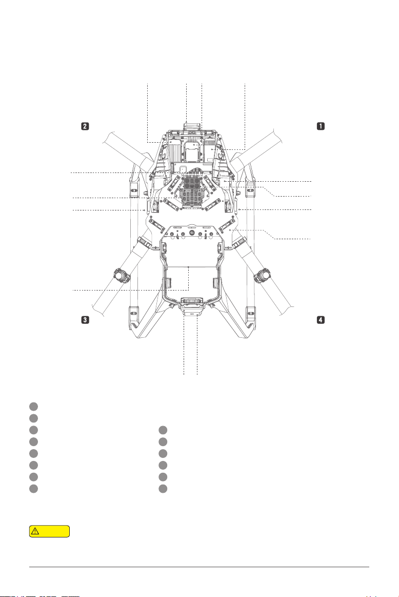
XAG P30 2020 User manual

Quick Start Guide
P30 2020
EN
Version 1.0

To Users
Dear user, thank you for choosing XAG products.
For safety purposes and the best experience possible, XAG recommends reading through the User
Manual and Disclaimer contained in this document before attempting to use the P30 Agricutural UAS
2020.
Contact Us
If you have any questions about this document, please contact our Technical Support via email: info@
xa.com
Click to View
See the contents below for a quick overview of the Manual; in a digital ver-
sion, click on each title to be redirected to the corresponding page.

Contents
List of Items 1
About P30 Agricultural UAS 2020 2
Airframe Assembly 4
Pre-Assembly Preparations 4
Arms Installation 5
Pipe & Line Connection 6
Reinstall the Removed Parts 6
Wiring Guidelines For P-series UAV Modules V1.1 7
Use Instructions 9
Activation 9
Prepare the Remote Controller 10
Download XAG AGRI APP 10
Pair the UAV 11
Preparing the Smart Battery 12
Preparing the Liquid Container 16
Description of Status Indicator/Buzzer 17
Check the UAV Status 17
Check Spray Status 18
Firmware Upgrade 19
Technical Specications 20
Disclaimer 22
WARNING 22
Flight Safety Instructions 23

www.xa.com/en
1
List of Items
Please carefully check whether the product contains all the items listed below and contact your dealer
if there are any missing items.
Airframe
×1
Tool Kit
×1
No. 3 Arm
Module
×1
No. 4 Arm
Module
×1
No. 1 Arm
Module
×1
No. 2 Arm
Module
×1
Automatic Liquid Container (16L)
×2
ControlStick
×1
USB-Type-C Cable
×1

www.xa.com/en 2
1
2
3
4
5
6
7
8
9
10
11
12
13
14
15
16
17
101112 9
13141517 16
8 7
42 3 5 61
About P30 Agricultural UAS 2020
The main structural components of the P30 Agricultural UAS 2020 are as follows:
Propeller / Blade
RTK Antenna (one on each side)
Smart Battery
2.4/5.8GHz Dual-frequency Antenna
(one on each side)
Landing Gear
Liquid Pump
Search Light
FC Backup Power
Terrain Sensor
XCope
Spraying Status Indicator
Nozzle
Arm
Head cover
ESC (Electronic Speed Controller)
Motor
Liquid Container
(Above) Figure 1: Airframe Module
Structure 1
(Below) Figure 2: Airframe Module
Structure 2

www.xa.com/en
3
23
20
18
24
21
19
25
22
26
27
28
29
30
31
18
19
26
22
28
31
27
23
29
30
25 24
21
20
Flight Controller / FC
HDLS Module
RTK Module
Antenna Frame
Power Grid Hub
Radar (Front)
Radar (Right)
Arm Position Number on Airframe
Antenna Hub
Central Hub
Flight Status Indicator Light (Tail Light)
Radar (Rear)
Radar (Left)
Airframe Nameplate (Serial Number/ QR Code)
[1]: The number of radar modules may vary depending on the UAV Version.
Figure 3: Airframe Module & Arm Position
No. ArmNo. Arm
No. Arm No. Arm
There are labels on the upper plate of the airframe and the aluminum sleeves of arms.
The numbers correspond to the position numbers of arms.
[1]
[1]
[1]
[1]
Warning

www.xa.com/en 4
Pre-Assembly Preparations
1. Disassemble the Head Cover
Lift the head cover up from the front, then
push it backwards.
2. Disassemble the Antenna Frame
Remove the antenna frame fixing screws, and
remove the antenna frame from the airframe.
3. Disassemble the Central Hatch Cover
Remove the fixing screws of the central
hatch cover to dismantle the hatch cover.
Before reassembling the arms, please ensure that the markings on the upper plate of the airframe
match the markings on the aluminum sleeves of the arms (Refer to Page 3, Figure 3: Airframe Module
& Arm Position). Incorrect assembly of the arms may cause accidents during ight.
1
2
Warning
Airframe Assembly

www.xa.com/en
5
Arms Installation
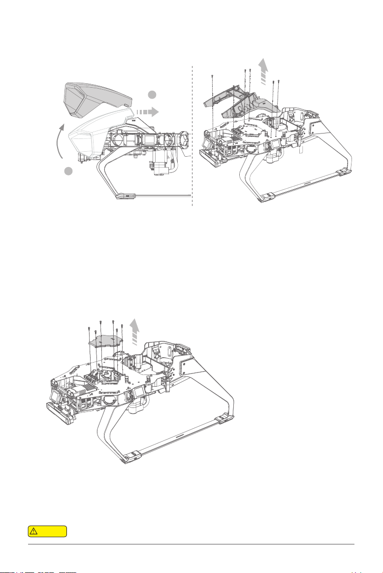
4. Dismantle the Fixed Sliders of No.1 and 2
Arms
Remove the screws on the stopper of No.1 Arm’s
top sliders, and then pull out the sliders. Please
follow the same steps to dismantle the No. 2
Arm.
6. Dismantle the Fixed Sliders of No.3 and 4
Arms
Remove the screws on the limiting stopper of
No.3 Arm’s top sliders. Pull out the sliders and
remove the carbon framed fasteners. Please fol-
low the same steps to dismantle the xed sliders
of No. 4 arm.
5. Install No.1 and 2 Arms
Insert the No.1 Arm into the designated posi-
tion along the airframe plate, then return the
top sliders to their original positions. Please
follow the same steps to install the No.2 Arm.
7. Install No.3 and 4 Arms
Insert the RTK feeder and the 2.4/5.8GHz feed-
er into No.3 Arm. Insert the arm into the des-
ignated position along the airframe plate, and
return top sliders and arm fasteners to their
original positions to complete the assembly.
Please follow the same steps to install No. 4
Arm.
BuckleSlider
Feeder
Make sure the arms remain horizontal while installing xed sliders.
Warning

www.xa.com/en 6
Pipe & Line Connection
9. Reassemble antenna’s central hatch cover
and frame head cover
Return the Central Hatch Cover, Antenna
Frame, and Head Cover back to their original
positions in order.
8. Correctly Connect the Circuits and Infusion Tubes
For instructions, see "Wiring Guidelines for the P-Series UAV Mod-
ules" on Page 7 and 8.
10. Finish Assembly
Load the battery and the liquid container
in order to complete assembly.
1
2
3
After assembly is completed, please check if the head
cover is rmly secured to avoid accidents during ight.
Before installing the central hatch cover, the
feeders and protective sleeves of No.3/4 Arm
must be installed in the slots as shown in the
gure.
Feeder’s Protective Sleeve
Warning
Warning
Reinstall the Removed Parts

www.xa.com/en
7
XCP/power
HDLS Module
RTK Module
4G – Left Antenna
2.4G/5.8G-Left Antenna
RTK-Left Antenna
4G–Right Antenna
2.4/5.8G - Right antenna
RTK–Right Antenna
Load System Power Supply
No.3 Motor
No.1 Motor
Propulsion System
No.4 Motor
Liquid Tank Sensor
Diagram-Antenna Hub
Diagram-Power Grid
Diagram-Central Hub
XCope Power Supply Load System
No.2 Nozzle No.1 Nozzle
No.4 Nozzle
No.3 Nozzle
No.2 Spraying Indicator Light
No.3 Spraying Indicator Light
No.1 Spraying Indicator Light
No.4 Spraying Indicator Light
Radar (Front)
Radar (Left) Radar (Right)
Radar (Rear)
No.1 Motor
Wiring Guidelines For P-series UAV Modules V1.1

www.xa.com/en 8
SBUS
Liquid
Liquid
Liquid
Liquid
Right
Front
Rear
Left
r
r
Uninterruptible Power Supply
High Data Link Module
Auxiliary Port1
FC Status Indicator
Note 1. Do not disassemble and assemble any modules while powered on.
2. Turn on the power supply only after all the modules have been installed.
Propulsion System
Wiring Guidelines For P-series UAV Modules V1.1
Diagram-Infusion Tube
Diagram-Flight Control System
Antenna Hub
Central Hub
Flight Controller
Power Grid Hub
No.2 Arm No.1 Arm
No.4 ArmNo.3 Arm
Load System
GNSS RTK Positioning Module
No.2 Nozzle
No.3 Nozzle No.4 Nozzle
No.1 Nozzle
Smart Battery
Terrain Sensor
PC Upgrade Porta
Backup XCope System

www.xa.com/en
9
Visit XAG User Registration Website at: https://agri.xaircraft.com/pm/#!/login
1. Open the "XAgriCentre" app and log in with your User Account Details.
2. Select “Scan QR”, and add your device by either entering the Serial Number or the Scanning the
2. QR Code of the Aircraft (This information could be found on the Airframe Nameplate).
3. Please Scan the QR Code on the Activation Card provided by Official XAG Partners to activate
2. your device.
4. The system will validate your QR Activation Code. Once it is validated, please select Activate
2. Device again to finalize the activation.
5. Your Device is now Activated.
Activation Steps
Activation
Use Instructions
* The QR code and serial number of the airframe can be found in the fuselage carbon frame beam, Please see Page
* 5, Icon 25 for Reference
* The QR code of activation card can be obtained from your dealer when you purchase the aircraft.
JUMP
JUMP
P30 2020
xxxxxxxx
xxxxxxxx
N0.1
2020-04-03
2020-04-03
2020-04-03
PPP 2020053001
FPPP 2020053001
P30 2020
PPP 2020053001
P30 2020
PPP 2020053001

www.xa.com/en 10
Prepare the Remote Controller
The XAG P30 Agricultural UAS 2020 needs to be used together with professional remote controllers
and APP. The available control mode combinations include:
①ACB1 CommBack (optional) + Smartphone;
②ACS1 ControlStick (optional);
③ACS2 ControlStick (optional).
Operation modes vary slightly depending on dierent remote controllers. Using the ACS2 ControlStick
as an example:
Press and hold the Power Button for 2 seconds twice to turn on the device.
• Connect the Device
1. Power ON your Smart phone, and connect to the ACS2 hotspot via Wi-Fi with password. (By default,
the hotspot name is ACS2_ XXX”, with XXX referring to the serial number indicated on the top of the
remote control, and the default password is 20070401.
2. Open the XAG AGRI APP again, and wait for connection. (the icon turns green)
• Turning on the ControlStick
Scan to visit XAG Academy
Download XAG AGRI APP

www.xa.com/en
11
Note: Only devices that have obtained the right to use at the XAG Service mini-program can be successfully paired.
Steps
①
Once your remote control and smartphone are wirelessly connected via hotspot, open XAG AGRI
APP,and select “Device”;
②Click “Add Device” to start device searching;
③
After the system prompts "Please power UAS again, or the RTK device is set to pairing mode",
restart the UAV for pairing;
④
If successfully paired, a “Successful Pairing” notication will display, and the device will be displayed
on the device interface;
⑤
Check if the UAS is functioning normally by selecting the UAS and "USE” button. If “IN USE” is then
displayed, it means the device is functioning normally.
Note: Before pairing, please visit the “XAG Service” WeChat mini-program and click "My Device"-"Scan QR Code to Add Device" to scan the QR
code printed on the airframe.
Pair the UAV

www.xa.com/en 12
[1] Device: Device as UAV or Charger.
The P30 Agricultural UAS 2020 is designed to be powered by B13860S Smart Battery. The Smart Bat-
tery contains a power button and six indicator lights.
The buttons/indicator lights are as follows:
• Battery ON/OFF
ON: The battery will be powered on after 2 long presses. With the power OFF, connect the device ,
press and hold the power button for at least 1 second, and release the button once all battery level
indicator lights ash at the same time. Then, press and hold the button for at least 1 second until a
beep is heard and the status indicator is on. This indicates that the battery has been powered on suc-
cessfully.
OFF: The battery will be powered o after 2 long presses. With the power ON, press and hold the
power button for at least 1 second, and release the button once all battery level indicator lights ash
at the same time. Then, press and hold the button for at least 1 second until a beep is heard and the
status indicator is o. This indicates that the battery has been powered down successfully.
•Checking Power Level
When the battery is OFF, press the power button once to display the battery level;
When the battery is ON, see the battery indicator lights for the battery level.
[1]
Fixed: Working
Slow Flash: Low
Temperature
Quick Flash: High
Temperature
Double Flash: Fault
Battery Level Indicators Status Indicator Power Button
Battery Level LED
1 LIGHT FLASH
1 LIGHT ON
2 LIGHTS ON
3 LIHGTS ON
4 LIHGTS ON
5 LIHGTS ON
2 LIGHTS
DOUBLE FLASH Self-locked
Remotely locked
3 LIGHTS
DOUBLE FLASH
Battery is locked due to low power level. Please
contact customer support to unlock the device.
Battery is locked remotely. Please contact customer
support to unlock device.
Status Description
Anti-tamper lock Battery is disabled. Please contact customer support to
unlock device.
4 LIGHTS
DOUBLE FLASH
Preparing the Smart Battery

www.xa.com/en
13
Battery Use Instructions
• Do not plug or unplug the battery when it is turned on, otherwise the power connector may be dam-
aged.
• Check the battery rmware before ight operation. If there is a new version, please update rst.
Flight loss caused by the user’s failure to update the battery rmware and software will be borne by
the user.
• The battery should be used between 10 ℃and 45 ℃(ambient temperature). Overheating (>45 ℃)
may cause the battery to ignite or explode.
• Do not connect the positive and negative poles of the battery with a wire or other metal objects to
avoid short circuiting.
• Do not immerse the battery in a corrosive liquid. When the battery is placed in clean water for heat
dissipation, please keep the water level between the Max and Min marks. Do not leave the battery in
water for more than 60 minutes. Otherwise, the liquid may ow into the battery and cause damage.
• If there is liquid or foreign matter on the battery terminal, wipe immediately and keep it clean. Oth-
erwise it may cause poor contact, resulting in loss of energy or charging failure.
• Please handle with care during use. Do not disassemble it, puncture its case or manually press the
battery, including but not limited to the following: Sitting on the battery, placing heavy objects on the
battery or otherwise putting pressure on the battery.
• Regularly check the battery terminal, plug and other components before use. Do not use alcohol or
other ammable agents to clean charging devices. Do not use a damaged charging device.
• When charging, place the battery and charging devices on at ground that is free of ammable or
combustible materials. Battery charging shall be watched over to prevent accidents.
•
For safety, when charging, a distance of more than 30cm shall be kept between two batteries, or
between a battery and a charger, to avoid the malfunction of the charger or the battery, and even
serious consequences such as re due to overheating.
• Before each ight, make sure the battery has completed charging; never operate with a full load
when the battery is not fully charged.
• It is strictly forbidden to use batteries other than those provided by XAG, or to dismantle or replace
a battery without authorization. For repairs or replacement, please contact XAG or a designated
dealer.The user shall bear the responsibility for battery accidents, ight failures or other accidents
caused by the use of batteries not provided by XAG.
• In case of ONE GREEN LIGHT FLASH after ight, please charge the battery to 40%-60% capacity be-
fore storage. Otherwise it may damage the battery. The battery should be recharged and discharged
every 90 days to maintain its activity.
• The battery should be stored in a dry environment at a temperature between 10-30℃. Do not place
the battery in a location that is too damp or has leakages.
• Do not charge the battery in a damp environment. Product damage caused by liquid immersion due
to reasons other than product quality (such as a damaged battery case) is not covered by the war-
ranty.
• The battery has been tested under controlled experimental conditions to be resistant to splashes
and water. However, such protective performance becomes less eective over time, and may dimin-
ish due to daily wear and tear.
RED LIGHT
ON Normal Normal
RED QUICK
FLASH Overheated Temporarily locked. Prohibited from
charging and usage.
RED SLOW
FLASH Low Temperature
Low temperature triggers charging
protection. Please keep battery
temperature at over 10ºC.
RED DOUBLE
FLASH Battery Malfunction Stop using immediately.
Battery Level LED Status Description
Checking Battery Status

www.xa.com/en 14
The battery must be charged with the charging devices designated by XAG. The user shall bear the re-
sponsibility for all the consequences caused by the use of the charging devices not designated by XAG.
Charging by Intelligent Super Charger Charging by Auto Super Charge Station
• Charging Battery
During the battery charging, the battery level indicators corresponding to the current battery level
will be on, while the remaining lights will ash in series, indicating that the battery is charging. After
charging is completed, the buzzer will beep for 30 seconds. Meanwhile, all battery level indicators will
ash for 2 minutes before the battery turns o automatically.
• The battery has been tested under controlled experimental conditions to be resistant to splashes
and water. However, such protective performance becomes less eective over time, and may dimin-
ish due to daily wear and tear.
• When the battery is found swollen, leaking, deformed, or damaged, stop using the battery immedi-
ately and contact XAG or your dealer promptly.
• The liquid inside the battery is highly corrosive. If it makes contact with your skin or eyes, rinse with
clean water and seek medical advice immediately.
• When disposing of the battery, please follow local laws and regulations. Protect the natural environ-
ment, and do not discard it irresponsibly.
Charger Status Indicators
Warning
LED
Green Light On
Green Light On
Green Light On
Green Light Flash
Green Light Flash
Red Light On
Red Light On
Red Light On
Red Light On
Red Light Flash
Status
Normal
Not Grounded
Device Fault
Device Overheated
Description
Normal input
Charging at risk
Temporarily locked.
Prohibited from output.
Temporarily locked.
Prohibited from output.
Idle
No Communication
Charging
Idle
Battery not connected
or communication failed.
Charging
Normal
Irregular
Communication
Battery Overheated
Communication succeeded.
Charging normally.
Communication between
charge port and battery failed.
Battery is overheated.
Status Type
Power Output
Charge Output
Charge Port

www.xa.com/en
15
Charger Use Instructions
• Please keep all battery terminals clean and avoid contact with metal objects.
• If there is liquid or foreign matter on the charge port, immediately clean and remove the substance.
Otherwise it may cause poor contact, resulting in short circuit or charging failure.
• Do not expose the Super Charger to sunlight or rain.
• Do not charge with AC power beyond the rated voltage range. Keep the Super Charger away
from ammable and explosive materials when charging, and do not leave it alone while it is being
charged.
• If an error or warning is issued during the charging process, please turn the power o immediately,
and resume use only after the product has been checked for safety.
• For safety, when charging, a distance of at least 30cm shall be kept between two batteries, or be-
tween a battery and a charger, to avoid the malfunction of the charger or the battery, and even seri-
ous consequences such as re due to overheating.
• Regularly check the battery terminals, plug and other components before use. Do not use alcohol or
other ammable agents to clean charging devices.
• When the Super Charger is found damaged, stop using immediately and contact XAG or your dealer.
• Do not use damaged chargers. For repairs or replacement, please contact XAG’s aftersales or desig-
nated dealers.
• Do not use the smart batteries or chargers other than the original ones manufactured by XAG. The
user shall bear the responsibility for charging accidents, battery failures, ight accidents or other ac-
cidents caused by the use of batteries or chargers not provided by XAG.
• Do not modify or disassemble the Super Charger without permission. The user shall be liable for any
consequence caused by the unauthorized modication and disassembly of the Super Charger.
• After use, remove the charge port from the Super Charger, and keep both in a safe, clean and cool
place.
• When the Super Charger is found damaged, stop using the battery immediately and contact XAG or
your dealer.

www.xa.com/en 16
[1]: It corresponds with Step 1 of 5 in total .
Preparing the Liquid Container
1. Place the liquid inlet tube into a barrel containing prepared liquid.
2. Press the ON/OFF button of the reller to power the machine on.
3. Place the container into the reller. If the container is positioned properly, a beep will be heard
from the buzzer.
4. Press the ON/OFF button of the container. When the power indicator is green, the container is ON.
5. Press the Rell button to transfer liquid into the container.
1 3
2
5
4
Less In Out More On/O
2L 4L 6L 8L 10L 12L 14L 16L 18L 20L Fault Battery Charge

www.xa.com/en
17
Description of Status Indicator/Buzzer
There are 3 indicator LEDs on the Automatic Liquid Reller, each indicating a status as follows:
RED LIGHT ON
GREEN LIGHT ON
Charging
OFF
YELLOW LIGHT ON
Charging completed
RED LIGHT FLASHES
RED LIGHT ON
RED LIGHT FLASH
LED Display Description
Battery Level
Charge
LED Display
Battery
50%-100%
25% -50%
5%-25%
Power level lower than 5%. Please recharge
in a timely fashion.
Charging circuit failure or battery
overdischarge
The reller detects that the container has been accurately
placed.
The reller fails to detect the placement of the container
when it starts operation.
The reller fails to connect to the container via Bluetooth
when it starts operation.
The oat of the container is stuck or the inlet tube or the
reller is blocked.
The reller detects irregular rotational speed.
The reller has completed the operation.
The filler detects low battery level. The operation is
suspended. All indicators ash eight times and the buzzer
beeps eight times before reller turns o automatically.
Charge the reller immediately.
RED LIGHT
ON
RED LIGHT
ON
RED LIGHT
ON
RED LIGHT
ON
LED Display DescriptionWarning/Beep
Once
Twice
Three
times
Four
times
Five
times
Six times
Eight
times
Fault
THREE LIGHT FLASHING (Green)
TWO LIGHT SLOW FLASH (RED)
GPS MODE
SAFE MODE
Auto
Check the UAV Status
Flight Status Indicator
ONE RED + ONE GREEN LIGHT FLASH
TWO LIGHT FLASHING (Green)
SOLID RED
QUICK FLASH PURPLE
QUICK FLASH BLUE
QUICK FLASH RED
THREE LIGHT FLASHING (RED)
Description
WEAK GPS SIGNAL
GOOD GPS SIGNAL
Flight controller is not initiated yet
or is being preheated after being
powered on
FC Formatted / Abnormal Parameter
Abnormal power system
GPS Error
Low Precision
Abnormal sensor (Exclude IMU)
IMU Error
Low voltage Warning
Status
Manual
Abnormal
Low Voltage
QUICK FLASH WHITE
The Flight Status Indicator Lights (Tail Lights) indicate the status of the UAV. See the table be-
low for details:
Table of contents
Other XAG Drone manuals

XAG
XAG P40 User manual

XAG
XAG RevoCast 2.0 P100 User manual

XAG
XAG P Series Owner's manual

XAG
XAG P100 Pro 2023 User manual

XAG
XAG P100 User manual

XAG
XAG M500 Remote Sensing UAS User manual

XAG
XAG P30 Guide

XAG
XAG P100 Operating and maintenance instructions

XAG
XAG XMISSION User manual

XAG
XAG V40 User manual
Popular Drone manuals by other brands

Gryphon Dynamics
Gryphon Dynamics GD-8 Assembly & instruction manual

WORLD TECH ELITE
WORLD TECH ELITE MINI ORION instruction manual

Autel Robotics
Autel Robotics Dragonfish Series Maintenance manual

Juguetronica
Juguetronica BRICK DRONE manual

Racers
Racers QUADRONE instruction manual

Protocol
Protocol AIR HOVER RACER instruction manual