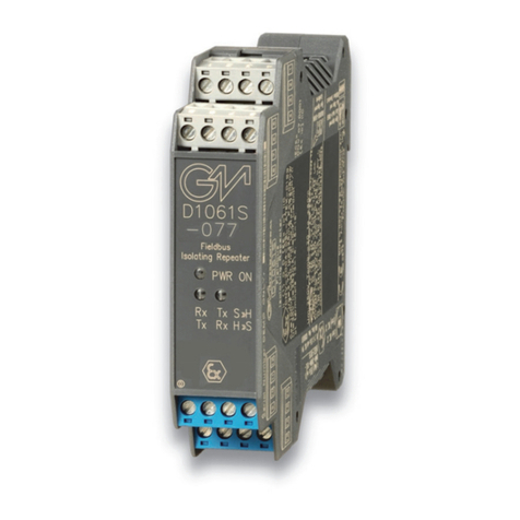
Hirschmann OZD FIP G3 Manual

Description and Operating Instructions
Fiber-Optic FIP Repeater OZD FIP G3
Port 1
System
Port 1
Port 2
Port 3
OZD FIP G3

Order numbers:
OZD FIP G3 933 847-421
Description and Operating Instructions 933 847-901
Fiber-Optic FIP Repeater OZD FIP G3
Description and Operating Instructions are protected by copyright.
All rights reserved. The reproduction, duplication, translation,
conversion to any electronic medium or machine-readable form
in whole or in part is not permitted
The following Description and Operating Instructions have been
produced by Richard Hirschmann GmbH & Co. to the best of the
company's knowledge. Hirschmann reserves the right to amend the
contents of this description and operating instructions without prior
notice. Hirschmann cannot provide any warranty or guarantee with
regard to the correctness or accuracy of the information contained
in this Description and Operating Instructions.
Under no circumstances can Hirschmann be held liable for any
damage arising from the use of the fiber-optic FIP repeater OZD
FIP G3.
© 1998 Richard Hirschmann GmbH & Co
The naming of registered trademarks in the following description
and operating instructions, even if not specifically identified as such,
should not warrant the assumption that such names are not subject
to the terms stipulated in the trademark and trademark protection
legislation and that they can therefore be freely used by anyone.

3
Version 1.0 11/97
Contents
1 Introduction . . . . . . . . . . . . . . . . . . . . . . . . . . . . . . . . . . . . . . . . . . . . . . . . . . . . . . . . . . . . . 25
2 Network Topologies . . . . . . . . . . . . . . . . . . . . . . . . . . . . . . . . . . . . . . . . . . . . . . . . . . . . . . 27
2.1 Redundant optical ring (two-fiber ring) . . . . . . . . . . . . . . . . . . . . . . . . . . . . . . . . . . . . . 27
2.2 Line topology without redundancy . . . . . . . . . . . . . . . . . . . . . . . . . . . . . . . . . . . . . . . . 29
3 Start-Up . . . . . . . . . . . . . . . . . . . . . . . . . . . . . . . . . . . . . . . . . . . . . . . . . . . . . . . . . . . . . . . . 31
3.1 Safety precautions . . . . . . . . . . . . . . . . . . . . . . . . . . . . . . . . . . . . . . . . . . . . . . . . . . . 31
3.2 Notes on CE marking . . . . . . . . . . . . . . . . . . . . . . . . . . . . . . . . . . . . . . . . . . . . . . . . . 31
3.3 Connection of optical bus lines . . . . . . . . . . . . . . . . . . . . . . . . . . . . . . . . . . . . . . . . . . . 32
3.4 Mounting repeaters . . . . . . . . . . . . . . . . . . . . . . . . . . . . . . . . . . . . . . . . . . . . . . . . . . 32
3.5 Connection of electrical bus lines . . . . . . . . . . . . . . . . . . . . . . . . . . . . . . . . . . . . . . . . . 34
3.6 Connection of power supply . . . . . . . . . . . . . . . . . . . . . . . . . . . . . . . . . . . . . . . . . . . . 34
3.7 Connection of signaling contact lines . . . . . . . . . . . . . . . . . . . . . . . . . . . . . . . . . . . . . . 35
3.8 ESD protection . . . . . . . . . . . . . . . . . . . . . . . . . . . . . . . . . . . . . . . . . . . . . . . . . . . . . . 36
4 LED Indicators . . . . . . . . . . . . . . . . . . . . . . . . . . . . . . . . . . . . . . . . . . . . . . . . . . . . . . . . . . . 37
5 Troubleshooting . . . . . . . . . . . . . . . . . . . . . . . . . . . . . . . . . . . . . . . . . . . . . . . . . . . . . . . . . . 38
6 Technical Data . . . . . . . . . . . . . . . . . . . . . . . . . . . . . . . . . . . . . . . . . . . . . . . . . . . . . . . . . . . 39
Contents

Version 1.0 11/97

5
1 Introduction
Version 1.0 11/97
1 Introduction
The fiber-optic FIP repeater OZD FIP G3 is designed
for use in optical FIP field bus networks. It permits
conversions of electrical FIP interfaces into optical
FIP interfaces and vice versa.
The repeaters can be integrated into existing FIP field
bus networks. OZD FIP G3 repeaters can also be used
to configure a complete FIP field bus network with
line or ring topology.
The mechanical structure comprises a compact, rigid
metal housing which can either be mounted on a top-
hat rail or on any flat base.
No adjustment is necessary during start-up.
Ports
The repeater has three mutually independent
channels (ports), each of which in turn consists of
a transmitter and a receiver.
Port 1 is a 9-pin Sub-D connector (male). Ports 2 and 3
are optical BFOC/2.5 (ST ®) sockets.
Power supply
The operating voltage is +24 V to +48 V DC.
A redundant power supply from two separate sources
is provided to increase operational reliability. The two
operating voltages can be supplied to two different
terminals of the 5-pole terminal block.
Both connections are decoupled via diodes in order
to prevent feedback or destruction resulting from
polarity reversal.
There is no load distribution between the sources.
With redundant supply, only the power supply unit
with the higher output voltage provides the bus
adapter with power.
Signaling contact
Various repeater malfunctions can be indicated via a
signaling contact (relay with floating contacts). The
connections of the signaling contact also terminate at
the 5-pole terminal block.
LEDs
Four two-color LEDs indicate the current operating
status and any malfunctions.
Port 1
System
Port 1
Port 2
Port 3
OZD FIP G3
5-pole
terminal block
for operating
voltage supply
and signaling
contact LED
indicators
Grounding
screw
Port 1
Electrical,
Sub-D
connector
Port 3
Optical,
BFOC/2,5
socket
Port 2
Optical,
BFOC/2,5
socket
Fig. 1: Fiber-optic FIP repeater OZD FIP G3. The illustration shows the position of the individual ports, the terminal block,
the LED indicators, and the grounding screw.

1 Introduction
6Version 1.0 11/97
Fiber-optic technology
The implementation of fiber-optic technology permits
very long transmission ranges and provides optimum
protection against EMI effects both along the trans-
mission link and (owing to the electrical isolation) at
the repeaters themselves.
Transmission rate
The fiber-optic FIP repeater OZD FIP G3 functions
at a transmission rate of 1 MBit/s (as defined in
EN 50 170).
Signal regeneration
The fiber-optic FIP repeater OZD FIP G3 regenerates
the signal shape and amplitude of the received data.
This function permits a maximum of 20 repeaters to
be cascaded via optical links.
FIP protocol
In a network topology as shown in Fig. 2, 3 and 4 (Ch. 2),
a response time must be taken into consideration at
the arbiter and in the data terminal equipment. The
data which is sent out, is returned to each optical port
by the neighboring device. This status signal is used
to monitor the output and the rings.
The response time is composed of the transfer time in
the optical fiber (5 ns/m) and the transfer time through
a repeater (< 1µs).
At a maximum transmission distance of 2.5 km, the
response time is as follows:
tresponse = 2 x 2500 m x 2 ns/m + 1 µs = 26 µs
If there is a break along the optical fiber, a predefined
waiting time of 30 µs is activated in the repeaters
affected by the fault (system LED red). This must be
taken into account when the system is planned.
Redundancy
Redundant signal transmission ensures a very high
degree of transmission reliability.
Redundant operating voltage supply can increase
operational reliability even further.

2.1 Redundant optical ring (two-fiber ring)
7
2 Network Topologies
Version 1.0 11/97
2 Network Topologies
2.1 Redundant optical ring (two-fiber ring)
Fig. 2: Network structure in redundant optical two-fiber ring topology
FIP bus line
Fiber optic cable
Terminal unit(s)/
bus segment(s) Terminal unit(s)/
bus segment(s) Terminal unit(s)/
bus segment(s) Terminal unit(s)/
bus segment(s)
Port 3
SE
OZD FIP G3
Port 2
SE
Port 1
Port 3
SE
Port 2
SE
OZD FIP G3
Port 1
Port 3
SE
OZD FIP G3
Port 2
SE
Port 1
Port 3
SE
OZD FIP G3
Port 2
SE
Port 1
This network topology is used in the case of an optical
link between data terminal units or bus segments.
The implementation of a redundant link with OZD FIP
G3 repeaters ensures a high degree of reliability.
A maximum of 20 repeaters can be operated in one
optical ring.
The failure of an optical cable between any two
OZD FIP G3 repeaters does not affect the availability
of the network.
The repeaters detect total failure of an optical link. The
port LED of the faulty link is deactivated and the failure
is indicated by illumination of the red system LED and
response of the signaling contact.
It is advisable to install the duplex optical cables of
the two optical channels along different routes.

2 Network Topologies 2.1 Redundant optical ring (two-fiber ring)
8Version 1.0 11/97
Fig. 3: Alternative wiring system for network structure in redundant optical two-fiber ring topology
FIP bus line
Fiber optic cable
Terminal unit(s)/
bus segment(s)
Port 3
SE
OZD FIP G3
Port 2
SE
Port 1
Terminal unit(s)/
bus segment(s)
Port 3
SE
OZD FIP G3
Port 2
SE
Port 1
Terminal unit(s)/
bus segment(s)
Port 3
SE
OZD FIP G3
Port 2
SE
Port 1
Terminal unit(s)/
bus segment(s)
Port 3
SE
OZD FIP G3
Port 2
SE
Port 1
Terminal unit(s)/
bus segment(s)
Port 3
SE
OZD FIP G3
Port 2
SE
Port 1
If problems are encountered with the configuration
of a redundant optical ring on account of excessively
long fiber-optic line sections, connections can also be
implemented as shown in Fig. 2.
In this case, each repeater is linked (in spatial terms)
with the next repeater but one. Two adjacent repea-
ters must be interconnected at the start and end of
every such line. This avoids individual “excessively
long“ fiber-optic line sections.

2.2 Line topology without redundancy
9
2 Network Topologies
Version 1.0 11/97
Fig. 4: Line topology without redundancy
FIP bus line
Fiber optic cable
Terminal unit(s)/
bus segment(s) Terminal unit(s)/
bus segment(s) Terminal unit(s)/
bus segment(s) Terminal unit(s)/
bus segment(s)
Port 3
SE
OZD FIP G3
Port 2
SE
Port 1
Port 3
SE
Port 2
SE
OZD FIP G3
Port 1
Port 3
SE
OZD FIP G3
Port 2
SE
Port 1
Port 3
SE
OZD FIP G3
Port 2
SE
Port 1
This network topology is used in the case of an optical
link between data terminal units or bus segments.
A maximum of 20 repeaters can be operated in an
optical line.
The first and last repeater in the line must be termi-
nated with an “optical short-circuit“ (see Fig. 4).
In this case, each input and output of the free ports
are connected to BFOC connectors via a short length
of optical cable.
2.2 Line topology without redundancy

2 Network Topologies
10 Version 1.0 11/97

3.1 Safety precautions
11
3 Start-Up
Version 1.0 11/97
3 Start-Up
The fiber-optic FIP repeaters OZD FIP G3 are only
to be used in the manner indicated in this version
of the “Description and Operating Instructions“.
Particular attention is to be paid to all warnings
and items of information relating to safety.
The fiber-optic FIP repeaters OZD FIP G3 are only
to be run off a safety extra-low voltage as per
IEC 950/EN 60 950/VDE 0805 of max. +48 V +10%.
Pay attention to the electrical limit values when
connecting voltage to the signaling contacts.
The connected voltage must also correspond
to a safety extra-low voltage as per IEC 950/
EN 60 950/ VDE 0805.
Never connect the fiber-optic FIP repeaters
OZD FIP G3 to 110 V – 240 V mains voltage.
The installation location is to be selected so as to
ensure compliance with the climatic limit values
indicated in the Technical Data.
3.1 Safety precautions
3.2 Notes on CE marking
The fiber-optic FIP repeater OZD FIP G3
complies with the specifications of the follo-
wing "European Directive" as well as with the
harmonized European Standards (EN) quoted
therein:
89/336/EEC Council Directive on the Approximation
of the Laws of Member States relating to Electro-
magnetic Compatibility (amended by Directives
91/263/EEC; 92/31/EEC und 93/68/EEC)
Compliance with the EMC limit values required by this
legislation (see Technical Data) presupposes obser-
vance of the “Description and Operating Instructions“
and in particular the installation specifications indi-
cated in Sections 3.3 - 3.8.
©Ensure adequate grounding of the fiber-optic FIP
repeater OZD FIP G3 by providing a low-impedance,
low-inductance connection between the top-hat
rail or base plate (or repeater itself - directly via the
grounding screw) and the local ground.
©Use only standardized FIP leads (to French Stan-
dard NF-C 46-604, Sect. 7) as the FIP bus line.
In accordance with the above EU Directive, the EU
Conformity Declarations are kept at the disposal of
the appropriate authorities by:
Richard Hirschmann GmbH & Co
Steckverbindungstechnik Industrie
(Industrial Interconnection Technology)
Abteilung SM
(SM Dept.)
Stuttgarter Straße 45 -51
D-72654 Neckartenzlingen

3 Start-Up 3.3 Connection of optical bus lines
12 Version 1.0 11/97
©Use a duplex fiber-optic cable with BFOC/2.5 (ST®)
connectors to connect the individual repeaters.
©Pay attention to the maximum cable length of the
fiber-optic cable as well as the possible types of
fibers specified in the Technical Data.
©Make sure that each optical input ais connected
to an optical output Jat the opposite end (“cross-
over link“).
The corresponding BFOC sockets of the two ports
are marked on the lower front panel.
©Ensure sufficient strain relief for the fiber-optic
cables and pay attention to their minimum
bending radii.
©Unused BFOC sockets are to be covered with the
protective caps supplied. Incident ambient light
and, in particular, great ambient brightness, can
affect the network.
The penetration of dust may impair operation of
the optical components
3.3 Connection of optical bus lines
I
J
I
J
Port 2
Port 3
Fig. 5: View of underside of repeater with optical ports 2 and 3
The FIP repeater OZD FIP G3 can either be mounted
on a 35 mm top-hat rail as per EN 50022 or directly on
a flat surface.
©The installation location is to be selected so as to
ensure compliance with the climatic limit values
given in the Technical Data.
©Make sure there is sufficient space for connection
of the bus and power supply lines.
©To facilitate installation of the fiber-optic cables,
they are to be connected before the repeaters are
mounted.
©If possible, the repeaters should only be installed on
a mounting plate or top-hat rail with low-impedance
and low-inductance grounding. If the mounted top-
hat rail and mounting plate are insulated, the repea-
3.4 Mounting repeaters
Port 1
Grounding
screw
Fig. 6: Position of grounding screw
ter must be provided with a low-impedance and
low-inductance ground connection directly via the
grounding screw.
No other grounding measures are required.

3.4 Mounting repeaters
13
3 Start-Up
Version 1.0 11/97
Mounting on top-hat rail
©Engage the upper snap-in hooks of the repeater in
the top-hat rail and press the underside (as shown
in Fig. 5) onto the rail until it engages.
©Disassembly involves pulling down the locking
slide.
Mounting on mounting plate
The repeater has three through-holes to permit moun-
ting to any flat surface, e.g. on the mounting plate of
a switch cabinet.
©Make three holes in the mounting plate corres-
ponding to the drilling template in Fig. 8.
©Secure the repeaters with machine bolts (e.g.
M 3 x 40).
©Ensure reliable electrical connection between the
repeater housing and the mounting plate. Place
toothed washers under the bolt heads to pierce the
varnish.
Locking
slide
Toothed washer
Port 1
System
Port 1
Port 2
Port 3
OZD FIP G3 61.2 mm
40.6 mm
81.2 mm
Ø 3 mm
Ø 3 mm
Fig. 7: Mounting repeater on top-hat rail Fig. 8: Mounting repeater on mounting plate

3 Start-Up 3.5 Connection of electrical bus lines
14 Version 1.0 11/97
Observe the following safety precautions:
©The shielding of the Sub-D connector is made of
metal to ensure safe ground current conduction
and must therefore be conductively connected to
the shielding plate of the connector attached to
the cable.
©FIP bus lines must not be used to connect FIP
repeaters to system components to which a
different ground potential is being applied.
Voltage differences > 500 V could destroy the
repeaters or cause the system to malfunction!
©FIP bus lines which are completely or partially
installed outdoors should not be connected,
otherwise any lightning strikes in the immediate
vicinity could destroy the repeaters. Optical cables
should be used for bus connections which are
routed out of buildings!
©The FIP repeater should only be supplied with a
regulated safety extra-low voltage to IEC 950/
EN 60950/VDE 0805 of +24 V to max. +48 V +10%.
©To enhance operational reliability, a redundant
supply from various sources is provided. The
operating voltages can be supplied in two ways:
– via terminal +24 V/48 V of the terminal block
– via terminal +24 V/48 V* of the terminal block
The common negative connection in the middle of
the terminal block is indicated by m.
©The two voltages can have any (even different)
values within the specified limits of +24 V/+48 V.
©If no signaling contact lines are connected to the
terminal block (see 3.7):
Secure the terminal block by screwing on the
flange.
3.6 Connection of power supply
6 / data +
7 / data –
8 / n.c.
9 / n.c.
n.c.
n.c.
n.c.
n.c.
n.c.
/ 1
/ 2
/ 3
/ 4
/ 5
Fig. 9: Port 1 - assignment of Sub-D connector
©Only bus lines to the French Standard NF-C 46-604
should be used as the FIP bus line.
©The electrical FIP interface (Port 1) is a 9-pole
Sub-D connector (male).
The pin assignment complies with the French
Standard NF-C 46-604
©A line which is fitted with 9-pole Sub-D connectors
(female) should be used to connect data terminal
equipment. Max. length 2 m.
©The electrical port must not be internally termi-
nated. The external termination must be provided
in or on the connector of the bus line in accordance
with the French Standard NF-C 46-604.
©The bus connection plug should be secured using
screws.
3.5 Connection of electrical bus lines

3.7 Connection of signaling contact lines
15
3 Start-Up
Version 1.0 11/97
©Floating contacts of a relay are provided as the
signaling contact at the 5-pole terminal block.
If the OZD FIP G3 is functioning correctly, the relay
picks up and the contact closes.
If a fault or power failure occurs, the relay drops
out and the contact opens.
©The following network and repeater faults can be
signaled at a master station:
Supply voltage
– No voltage supply (with redundant supply:
failure of all supply voltages)
Internal device fault
Received data
– No data received at Port 2 and/or Port 3
(e.g. cable breakage)
– No data received at any port for over 500 ms
©Limit values of relay contact
– Max. switching voltage 60 V DC; 42 V AC
– Max. switching current: 1.0 A
– Max. switching capacity: 30 W
©The voltage connected to the relay must
correspond to a safety extra-low voltage
to IEC 950/EN 60 950/VDE 0805.
©Always ensure that the correct assignment is
provided for the 5-pole terminal block. Make sure
that the connecting leads of the signaling contacts
are adequately insulated. Incorrect assignment can
result in destruction of the repeaters.
©Secure the terminal block by screwing on the
flange
3.7 Connection of signaling contact lines
+24 V/48 V
+24 V/48 V*
Securing
flange
Error
Fig. 11: Signaling contact - assignment of 5-pole terminal block
Fig. 10: Operating voltage supply - assignment of 5-pole terminal
block
+24 V/48 V
+24 V/48 V*
Securing
flange
Error

3 Start-Up 3.8 ESD protection
16 Version 1.0 11/97
Protective
plugs
Fig. 12: Insertion of protective plugs into terminal block
©When the voltage supply and signaling contact
lines have been connected, the access points to the
connection screws of the terminal block must be
sealed using the supplied protective plugs.
©Ensure that the insulation of the connection lines
reaches the interior of the terminal block.
3.8 ESD protection

17
4 LED Indicators
Version 1.0 11/97
4 LED Indicators
System
Green: Repeater in operation, data traffic occurring
Red: – No data received at Port 2 and/or Port 3
(e.g. cable breakage)
– No data traffic at any port for over 500 ms
Not lit: – No voltage supply
– Internal device fault
Port 1 (electrical)
Green: Input signal applied
Orange: No input signal at any port for over 500 ms
Not lit: Currently no input signal at this port
Port 2 (optical)
Green: Input signal applied
Orange: No input signal at any port for over 500 ms
Not lit: Currently no input signal at this port
Port 3 (optical)
Green: Input signal applied
Orange: No input signal at any port for over 500 ms
Not lit: Currently no input signal at this port
Fig. 13: LED indicators on front panel
Port 1
System
Port 1
Port 2
Port 3
OZD FIP G3

5 Troubleshooting
18 Version 1.0 11/97
5 Troubleshooting
LED indicator
System ©Not lit
©Red
Port 1 ©Not lit
©Orange
Port 2 ©Not lit
©Orange
Port 3 ©Not lit
©Orange
Possible causes
– Failure of supply voltage
– Internal device fault
– No data received at Port 2 and/or Port 3, e.g. cable breakage
– No input signal received at any of the 3 ports for over 500 ms
– Currently no input signal at this port
– No input signal received at any of the 3 ports for over 500 ms
– Currently no input signal at this port
– No input signal received at any of the 3 ports for over 500 ms
– Currently no input signal at this port
– No input signal received at any of the 3 ports for over 500 ms
Signaling contact
Signal
Signal
Signal
Signal
Signal
Note
“Unlit“ port LEDs do not indicate a fault.

19
6 Technical Data
Version 1.0 11/97
6 Technical Data
Operating voltage +24 V –20% to +48 V +10%, non-interchangeable
Safety extra-low voltage
Current input for +24 V 150 mA
for +48 V 85 mA
Transmission rate 1 MBit/s
Cascadability 20 repeaters
Signal processing time <1 µs
(any input/output)
Electrical port
Input/output signal FIP level
PIN assignment of Port 1 To French Standard NF-C 46-604 (see Sect. 3.5)
Length of FIP cable 2 m
Connection capability Max. 2 terminal data devices
Electrical isolation
– Shielding/housing No
– Data lines/shielding Yes
Optical interface
Typ. wavelength. 860 nm
Launchable optical power
– into fiber G 50/125 –17.5 dBm
– into fiber G 62.5/125 –15.0 dBm
Receiver sensitivity –28 dBm
Transmission distance
with 3 dB system reserve/
line attenuation
–with fiber G 50/125 0 - 2.5 km/10,5 dB
–with fiber G 62.5/125 0 - 2.8 km/13,0 dB
Optical connector BFOC/2.5 (ST®)
EMI protection
Noise emission Satisfies EN 55011, class B
Noise immunity Satisfies EN 61000-4-2…5
Ambient temperature 0 °C to +60 °C
Storage temperature –40 °C to +70 °C
Relative humidity <95% (non-condensing)
Degree of protection IP 40
Weight 500 g
Dimensions 39.5 x 110 x 73.2 mm
Housing material Die-cast zinc/sheet aluminum

Richard Hirschmann GmbH & Co
Steckverbindungstechnik Industrie
(Industrial Interconnection Technology)
Stuttgarter Strasse 45 - 51
D-72654 Neckartenzlingen
Tel.: ++49/7127/14-1479
Fax: ++49/7127/14-1495/-1496/-1502
Other manuals for OZD FIP G3
1
Table of contents
Other Hirschmann Repeater manuals
Hirschmann
Hirschmann OZD Genius G12 User manual
Hirschmann
Hirschmann OZD FIP G3 User manual
Hirschmann
Hirschmann OZD 485 G12 PRO User manual
Hirschmann
Hirschmann OZD Profi 12M User manual
Hirschmann
Hirschmann OZD 485 G12 BAS User manual
Hirschmann
Hirschmann OZD Profi 12M G12 PRO User manual
Hirschmann
Hirschmann OZD Profi 12M G11 User manual
