Hitachi CX-W300 User manual

0
HITACHI
•SERVICEMANUAL
TY
No.
682E
CX-W300
[UC,E,E(BS),W,W(UN),W(AU)]
KHMzyxwvutsrqponmlkjihgfedcbaZYXWVUTSRQPONMLKJIHGFEDCBAV Of-N
MOIT038
J'
HSR
[{8
^CAUTIOIM
DANGER
Invisible
laser
radiationwhenopenandinterlocksfailedordefeated.AVOID
DIRECT
EXPOSURE
TOBEAM.
^GEFAHR
Unslchtbare
Laser-Strahlungwenn
Interlook
(Blockierung)funktionsuntüchtigoderabgeschaltet.
UNMITTELBAREN
KONTAKTMITDEMSTRAHLUNBEDIGTVERMEIDEN.
^DANGER
Faire
trés
attention
auxradiationsémisespariefaisceau
laser
invisibleaudéfaillanceduverrouillage.
^NEJAMAIS
S'EXPOSER
DIRECTEMENTAU
FAISCEAU.
^VARNING
Narapparatenöppnats ochskyddsanordningenfelarellersattsur
funktion
forekommerosynliglaserstralning.
UNDVIK
DIREKTE
BESTRALING.
^
ADVARSEL
Narapparatetabnes^ogbeskyttelsesanordningenikkevirkerellersaettesunaffunktion,forekommerderusynlig
laserstraling.
UNDGA
DIREKTE
BESTRALING.
^
ADVARSEL
^
Nardennedelen erapensomfelgeavatlasener
utkoplet
ellerikkefungerer,eksistererdetusynliglaserstraling.
UNNGAA BLIUTSATTFOR
DIREKTE
BESTRALING!
^VARIOITS
Laite
lahettaanakymatöntalasersateilya,kunseavataanjakun
sisaiset
turvalukot eivattolml.VARO
JOUTUMASTA
ALTTIIKSI
SATEILYLLE.
CONTENTS
SPECIFICATIONS
2
DISASSEMBLY
INSTRUCTIONS
3
INSTRUCTION
FOR
HANDLING
OPTICAL
SYSTEM
BLOCK
PICKUP
4
PICKUP
REPLACEMENT
5
DIAL
POINTER
SETTING
7
TEST
POINT
LOCATIONS
(TUNER)
10
TUNER
ALIGNMENT
SETUP11
TUNER
ALIGNMENT
12
TEST
POINT
LOCATIONS
(CD)18
CIRCUIT
ADJUSTMENT
20
TROUBLESHOOTING
CHARTS
22
SCHEMATIC
DIAGRAM
31
PCB
VIEWS
43
WIRING
DIAGRAM
53
EXPLODED
VIEW
57
ELECTRICAL
PARTS
LIST
65
I
SPECIFICATIONS
AND
PARTS
ARE
SUBJECT
TO
CHANGE
FORIMPROVEMENT.
CD
PLAYER
INCORPORATED-
HiGHPERFORMANCE
PORTABLE
CREATIVE
SOUND
SYSTEM
November1991YOKOHAMAWORKS

CX-W300
1
SAFETY
PRECAUTIONS
Thefollowingprecautionsshouldbeobservedwhenservicing.
1.
Sincemanypartsintheunithavespecialsafety-relatedcharacteristics,alwaysusegenuineHitachi's
replacementparts.Especiallycriticalpartsinthepowercircuitblockshouldnotbereplacedwithother
makers.
CriticalpartsaremarkedwithA inthecircuitdiagramandprintedwiringboard.
2.Beforereturning a repairedunittothecustomer,theservicetechnicianmustthoroughlytesttheunitto
ascertainthatitis completelysafetooperatewithoutdangerofelectricalshock.
SPECIFICATIONS
1;^
GENERAL
SECTION
Power
Supply:
Power
Consumption:
Power
Output:
Speakers:
Dimensions:
Weight:
AC:120V,60Hz[forUC]
AC:230V,50Hz[forE]
AC:240V,50Hz[forE(BS)]
AC:110-120V/220-240V,50/60Hz
[for
W,W(UN),W(AU)]
DC:9V["D"CELL(lECR20).--^
SUM1
X 6 orequlpment]
16W
20W P.M.P.(ACoperation)
3
W X 2 (10%T.H.D.DCoperation)
10cmX 2
3
n
550(W)X 185(H)X 196(D)mm
4.5kg(withbatteries)
.
RADIO
SECTION
Circuit
System:FM/MW/LW-3bands
Tuning
Range:
superheterodyne[forE,E(BS)]
FM/SW/MW-3bands
superheterodyne
[for
W,W(UN),W(AU)]
FM/MW-2bands
superheterodyne[forUC]
FM:
87.5to108.5MHz[exceptUC]
FM:
88to108MHz[forUC]
SW:3.9to12MHz[forE,E(BS)]
MW:
520to1,620kHz[exceptUC]
MW:
520to1,740kHz[forUC]
LW:148to287kHz[forE,E(BS)]
Intermediate
Frequency:
Antennas:
(Aerials)
FM:
10.7MHz
MW/LW:465kHz[forE(BS)]
SW/MW/LW:455kHz
[exceptE(BS)]
FM/SW/SW2:Rodantenna
SW/MW/LW;Builtinferrite
antenna
TAPE
RECORDER
SECTION
Tape:
Tracl<
System:
Tape
Speed:
Recording
System:
Erasing
System:
Frequency
Response:
Output:
Load
Impedance:
Cassettetape
4tracks2 channelsstereo
4.75cm/sec.
ACbias70kHz
Magnet
Normal:70to10,000Hz
CDout:0.5V
1
ka
Headphones:8 to100Q
Speaker: 3 fi
.
CD
PLAYER
SECTION
Playing
Time:
Diameter:
Sampling
Frequency:
Quantization
Number:
Frequency
Response:
Approx.60minutes/oneside
120mm/80mm
44.1
kHz
16bitlinear/channel
20to20,000Hz
Specificationsaresubjecttochangewithoutnoticefor
performanceimprovement.
The
caution
labels
onlaser
usage.
•
NEVER
TOUCH
THELENS.
•
NEJAMAISTOUCHERL'OBJECTIF.
•
DIE
LINSE
NIEMALS
BERÜHRENI.
•
NOTOQUE
NUNCA
LALENTE.
mWLISERIItDIHIMI
FlllEOOROEFEHED.m
mam
m»
mmi mm
u
Mne
ESI
OUVERI
ET
gUE
IE
«EffiOUUUE
ESI
IKFECIUEUI
«1
COmOIJIIIE.
EVIIEII
lEtPOSITIM
IMIECIE
011
IE
«im
Cfor
E,E (BS). W,W (UN), W (AU),]
tfor
UC]
SUT3e
Cfor
E,E (BS), W,W (UN), W (AU),3
O
1
(T—^——Tl
™
0
CsiS-^-^
_
^
CLASS1
LASER
PRODUCT
3

CX-W300
DISASSEMBLY
INSTRUCTIONS
^
^^''Y8J
1.
Openthecassettecoversandtakeoutthe
cassette
tapes.
2.
Removethe
battery
coverandbatteries.
3.Removeeightscrews@ holdingtherear
cabinet.' ^
4.Removetwoscrews(ë)andtwoscrews
(§)holdingtheCDmechanismkit.
5.Removetwoscrews(§)holdingtheCD
PCB.
6.Removefourscrews(E)holdingtheCD
mechanism.
7.Removetwoscrews(F)holdingthetuner
chassis.
1zyxwvutsrqponmlkjihgfedcbaZYXWVUTSRQPONMLKJIHGFEDCBA
i9ob Bnifitob(c>
Figure1 ^Q^D
8.Removefourscrews@ holdingthe
mainPCB.
9.Removethevolumecontrolpanel.
10.Removeonescrew(§)holdingthe
select
switcharm.
Figure2
11.
RemovesixscrewsQ) holdingthe
cassette
mechanism.
Figure3 Figure4
Checl<
that
exposedpartsareacceptablyinsulated
from
thesupplycircuitbeforereturningthe
instrumentrepairedtothecustomer.
Checking
method
Power(Operate)switchissettoON.
Next,
measuretheresistancevaluebetweenthe
both
polesofattachmentcup(Powersupplyplug)
andtheCDOUTterminalofrearplateandcheck
that
theresistancevalueis500kohmsormore.
(Exposed
part)
qu)ISDiJtsV(E
Insulationtester(DC
500V)

CX-W300
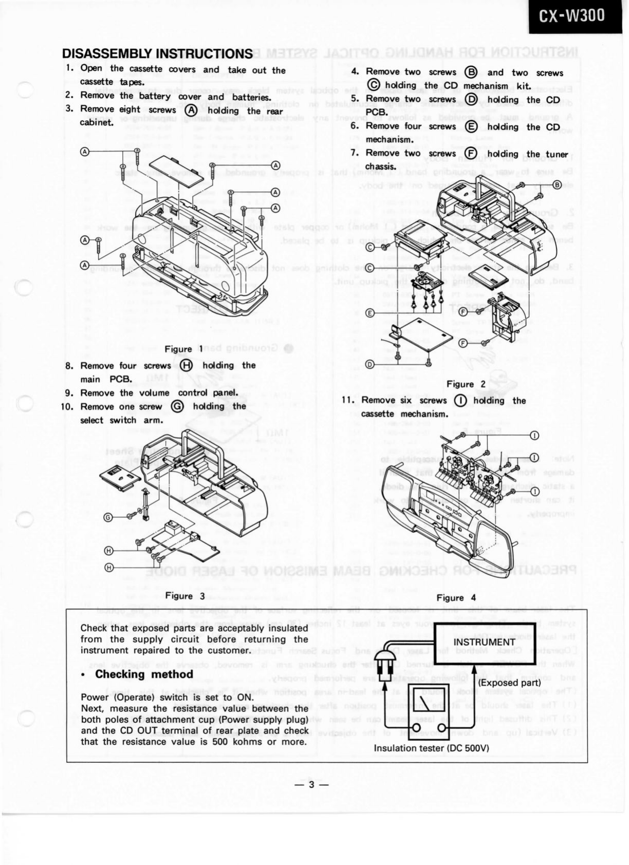
INSTRUCTIONFORHANDLINGOPTICALSYSTEMBLOCKPICKUP
Electrostaticbreakdownofthelaserdiodeinthe opticalsystemblockmayoccurduetoa potential5;
differencecausedbyelectrostaticchargeaccumulatedonclothing,humanbody,etc.g
Agroundmustbeprovidedasfollowstopreventanyelectrostaticchargeduringunpackingorrepair
work.;
1.
GroundforHumanBody^^'^'^^' ^ - ^ " ® '
Besuretoweara groundingband( 1 Mohm)thatisproperlygroundedtoremoveanystatic
electricitythatmaybechargedonthebody.
2.GroundforWorkbench: , . ^
Besuretoplacea conductivesheet( 1 Mohm)orcopperplate withpropergrounding onthework
benchorothersurfaceonwhichthepickupistobeplaced.
3.
Becausethe staticelectricitychargeontheclothingdoesnotdischargethrough thebody grounding'
band,
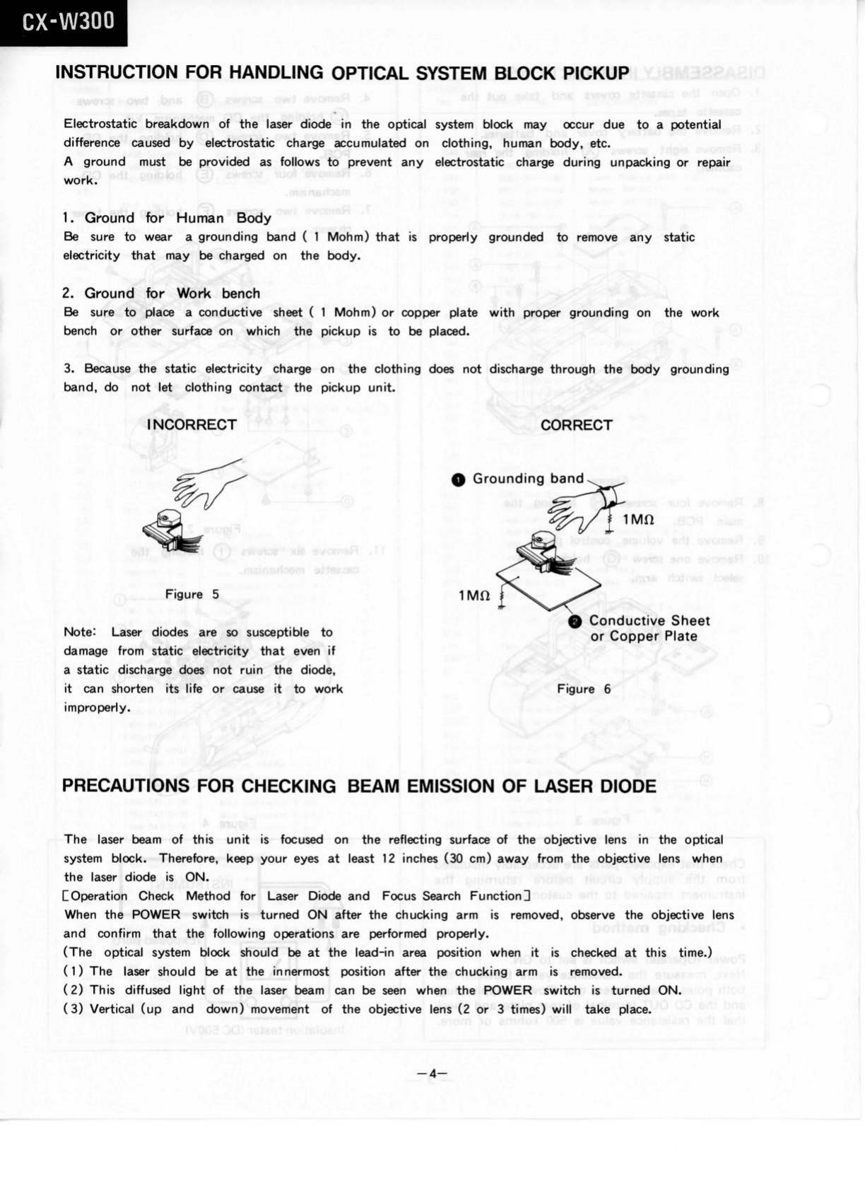
donotletclothingcontactthe pickupunit.
iINCORRECT "<3)
Figure5
Note:
Laserdiodesaresosusceptible to
damagefromstaticelectricitythatevenif
astaticdischargedoesnotruinthediode,
itcanshortenitslifeorcauseittowork
improperly.
CORRECT
0Groundingband
1Mn
^.
V.!*
ovanafl.8
.Rins(ioiiwif:mk.'
ConductiveSheet
orCopperPlate
Figure6
PRECAUTIONSFORCHECKINGBEAMEMISSIONOFLASERDIODE
Thelaserbeamofthisunitisfocusedonthereflectingsurfaceoftheobjectivelensinthe optical1
systemblock.Therefore,keepyoureyesatleast12inches(30cm)awayfromtheobjectivelenswhen^ j
thelaserdiodeisON.|.,^
j-iinnii
monj
llOperationCheckMethodforLaserDiodeandFocusSearchFunctionHi
WhenthePOWERswitchisturnedONafterthechuckingarmisremoved,observethe objectivelens
andconfirm thatthe followingoperationsareperformedproperly.i
(Theopticalsystemblockshouldbeatthelead-inareapositionwhenitischeckedatthistime.)-.
(1)Thelasershouldbeattheinnermostpositionafterthechuckingarmisremoved.;1
(2)ThisdiffusedlightofthelaserbeamcanbeseenwhenthePOWERswitchisturnedON.ï ritoJ|;
(3)Vertical(upanddown)movementoftheobjectivelens(2or3 times)willtakeplace.'-'^

CX-W300
PICKUP
REPLACEMENT
Caution:
Laser
diodesareextremelysusoeptibietodamage
from
static
electricity.
Even
ifa staticdischargedoesnotruinthediode,\
itcanshortenits
life
or
cause
ittoworkimproperly.
Whenreplacingthepickup,usea oonductivemat,a
groundedsolderingiron,andsoon,toprotectthelaser
diode
from
staticdamage.
IIU( 'io,9iittuo9>teT.d
HfiftezyxwvutsrqponmlkjihgfedcbaZYXWVUTSRQPONMLKJIHGFEDCBA
iuo
Ground Conductive
Wrist
Band
for
Body
in
1.
RemovetheCDmechanismassemdyby
referringtodisassemblyinstructions.
2.
Removetwosorews@ holdingtheCD
PCB.
(SeeFigure8.)
3.
Removefoursorews(§)holdingtheCD
mechanism.
(SeeFigure8.)_ .\
4.
Removewasher(D)holdingthegearand
removethegear.(SeeFigure9.)
5.Removetwosorews(E). (seeFigure9.)
,rroï
-.tqsiR
.Cf
Figure9

CX-W300
6.
Takeoutthepick-up(T).Thenpull
outtheshaft@.(SeeFigure10.)
^boib
erttT>
'feesf
er)*Jaej
(9
oiJstE
^0« n9v3
ja
bsöriuoig
2mo^^
aboib
Figure10
7.
PlaceshortingroundasshowninFigure11
andremovebothwireconnectors.
8.
Unpacknewpick-up.
White
Red
lli
9.
Afteryouconnectthewireconnectors,
desolderandremovetheshortingtab.
(See
Figure12.)
10.
Replaceshaftandpick-up.
11.
Replacetwoscrews.
12.
Replacegearandwasher(B).
13.
Replacefourscrews(g)holdingtheCD
mechanism.
14.
Replacetwoscrews(K) holdingtheCD
PDB.
Short
Round
bns
{.e
s
Figure12
Short
Round
15.
ReplacetheCDmechanismchassis.
-6-

CX-W300
DIALPOINTERSETTING
i.......,-
• •dbluorizti,^i6q9lzyxwvutsrqponmlkjihgfedcbaZYXWVUTSRQPONMLKJIHGFEDCBA'\o soiv
1.
Removethetuner
chassis.
2.
TurnthePVCgearcounterclockwise.
3.
Turnthetuningknobandslidethepointertothecheckpositiononthetuner
chassis.
4.Replacethetuner
chassis.
dtiW
sni
166I'
,>iv.v>J
bfxiT
31io,
c
TuningKnob
.3811^ 1-,,
Check
Position
8-
-7-

CX-W300
1
f;;;;^^:
Whenever a unitisbroughtinforserviceorrepair,itshouidbecleanedandlubricatedandthe
headshouidbedemagnetized.
lUOO
1
1.
Cleaning:CleantheheadandalltapehandlingsurfacesusingStandardcleanerandcottonswabs.
Wipedry.
2.Demagnetization:Donotusemagnetizedtoolsnearthe
head,
sincetheycan magnetizeit.With
normaluse,theheadwillretainsmallamountsofresidualmagnetismwhichresults inincreased
noiseandlossofhigh-frequencyresponse.Usea Standardtapeheaddemagnetizertodemagnetize
theplayback
head.
3.
Lubrication:Usea high-gradeofspeciallyformulatedlubricantinthe appropriateplaces.
Lubricationisnormallyrequiredonlywhenpartstendto
bind,
orafterlongperiodsofuse.
Usealllubricantssparinglyandavoidcontactwithotherparts.
.S
Pre-AdjustmentProcedures* s ^^-^^
1.
Besuretodemagnetizeandcleantheheadbeforeproceedingwithheadadjustment.
2.Neverusea magnetizedscrewdriverfortheheadadjustment.
TapeSpeed(Figure14)
1.
Removethe frontcabinet.
2.Connecta frequencycountertotheheadphonejackparallelwitha 32ohmnon-reactivedummy
load.zyxwvutsrqponmlkjihgfedcbaZYXWVUTSRQPONMLKJIHGFEDCBA
^•
-v-'^^-'VN//-/-
/-i-i'
(.^- - '.-.v
3.
Adjustthepot,resistorinthemotortomakethecounter reading3015Hzwhileplayingback
3000Hztest tape.
ToAdjust
Screwdriver
AdjustHoll
Motor
Figure14
-8-

CX-W300
:^*AHTS..5T
{R3HUT)a^OiTAOOJ
Playback
HeadAzimuthAdjustment
(Cassette
1)(Figure15)
1.ConnectanSSVMor
oscilloscope
to
each
oftheheadphonesjack(dummyload32ohm).
2.
Playbackan8 kHztesttapeandturntheazimuthadjustment
screw
toobtainthemaximum
outputlevelofthe
left
andright
channels,
intheforwardandreverseplaymodes.
3.
Whentheoutputlevelofthe
left
andright
channels,
andforwardandreversepositiondiffers, zyxwvutsrqponmlkjihgfedcbaZYXWVUTSRQPONMLKJIHGFEDCBA
1..
readjusttomaketheboth
channels,
andbothdirectionsatthesamelevel.!
4.Afteradjustment,
secure
the
screw
withlockpaintorglue.
Record/Playback
HeadAzimuthAdjustment
(Cassette
2)(Figure15)
1.
ConnectanSSVMor
oscilloscope
to
each
oftheheadphonejack(dummyload32ohm).
2.
Playbackan8 kHztesttapeandturntheazimuthadjustment
screw
toobtainthemaximum
outputlevelofthe
left
andright
channels.
3.
Whentheoutputlevelofthe
left
andright
channels
differs,readjusttomaketheboth
channels
atthesamelevel.
4.Afteradjustment,
secure
the
screw
withlockpaintorglue.
or-9-

CX-W300
TEST
POINTLOCATIONS(TUNER)
Cfor
E,E (BS), W,W (UM), W (AU)3
-10-

CX-W300
TUNER
ALIGNMENT
SET
UP
Tkl3MH0üA
FI3VIUT
LoopAntenna
(8i
bnt
SSVM
Scope
Headphone
I
I
J
L
MA
39*8
Dummy
Load
32ohm
I
Figure
18
,«.M
'\J U_•
Ssope
FM
IF
SweepGenerator Set
-O
V H O-
Scope
signal
—OH Out
O—
Ceramic
0.022uF
H(
-OV InO-
I
TP3
O-
-OGNDGNDO--OTP2
FMSignalGenerator
JLCeramic
"o.OluF
TfT
'-i
Set
Figure
19
SSVM
Scope
inzyxwvutsrqponmlkjihgfedcbaZYXWVUTSRQPONMLKJIHGFEDCBA
O
FM
Dummy
I
to
TP2L
Headphone
Jack
^_J{L^ I
I
Dummy
Load
32ohm
Figure
20
cjsiB
FM
Dummy
FMSG.
(8f
bnfe
8.?syiuytï)inamngilA"?>1'.VJ
R1=Z0
ZO=
Output
impedance
ofFM
SG.
- - ^
R2=75
ohm-zo/
2
Sgüfc'i
g.linuT
t !
^I
Figure
21,vpc
^ Set SSVM Counter
TP5
O-
TP2
O-
1^
)T
Het I
I
J
L
ili
pniAOBil
' i
ir f
Dummy
Load
330k
ohm
Figure
22
-11-

CX-W300
TUNER
ALIGNMENT
Cfor
E,E (BS):
AMIF
Alignment(Figures
16and18)
I
I
l!,.n..HMA
Step
Alignment
Frequency
ofSignal
Generator
Tuning
Dial
Setting Adjustment Remark
s
li
IF
Calibration 1000
kHz
1000
kHz
T2 Obtainsine-wave
and
maximumamplitude.
Max.
(
MWRF
Alignment(Figures
16and18)
11
O—I
1
vo
O—j—I
; O H V
Step
Alignment
Frequency
ofSignal
Generator
Tuning
Dial
Setting Adjustment
Remarks
TuningRange
Calibration 515
kHz
Low
end
L
5
1635
kHz
High
end
Obtainsine-wave
and
maximumamplitude.
TC
5
Adjustment
of
Tracking 600
kHz
600
kHz
L
3
Max.
1400
kHz
1400
kHz
TC
3
Repeat
the
aboveadjustments.
LW
RF
Alignment(Figures
16and18)
Step
Alignment
Frequency
ofSignal
Generator
Tuning
Dial
Setting Adjustment
Remarks
TuningRange
Calibration 145
kHz
Low
end
L6
290
kHz
High
end
Obtainsine-wave
and
maximumamplitude.
TC
6
Adjustment
of
Tracking 150
kHz
150
kHz
L
4
Max.
280
kHz
280
kHz
TC
4
Repeat
the
aboveadjustments.
-12-

CX-W300
JA
H3HUT
FMIFAlignment(Figures16and19)
Step
Alignment
Frequency
ofSignal
Generator
Tuning
Dial Adjustment Rpmarlo:
Step
Alignment
Frequency
ofSignal
Generator Setting
Adjustment
1 IF
Calibration 10.7MHz
Low
End TurnL 7
fully
counter
clockwise.
2
T1 Obtainsymetricalcurve
andmaximumamplitude.
1
r 1
i Max.
10.7MHz
3
L
7 ObtainS curveand
maximumamplitude.
1
1
Max.
u
10.7MH2
80TzyxwvutsrqponmlkjihgfedcbaZYXWVUTSRQPONMLKJIHGFEDCBAV' hna
rlgiH
FMRFAlignment(Figures16,20and21)
I5 zyxwvutsrqponmlkjihgfedcbaZYXWVUTSRQPONMLKJIHGFEDCBA
i
c
Step
Alignment
Frequency
ofSignal
Generator
Tuning
Dial
Setting
Adjustment
Remarks
TuningRange
Calibration
87.35MHz
Low
end
L
2 Obtainsine-waveand
maximumamplitude.
108.25
MHz
High
end
TC2
Adjustmentof
Tracking
90MHz 90MHz
L
1
106MHz 106MHz
TC1
Max.
Repeattheaboveadjustments.
Ü
-1
I
sHM
01
•>I
'
S
^>lt.A..I»-i
i \
-13-

CX-W300
TUNER
ALIGNMENT
Cfor
W,W (UN), W (AU)zyxwvutsrqponmlkjihgfedcbaZYXWVUTSRQPONMLKJIHGFEDCBA1
AMIFAlignment(Figures16and18)
(erzyxwvutsrqponmlkjihgfedcbaZYXWVUTSRQPONMLKJIHGFEDCBAbns 8feeiuei"^*tnemneilAM'^^
Step
Alignment
Frequency
ofSignal
Generator
Tuning
Dial
Setting Adjustment
Remarks
IF
Calibration 1000kHz 1000kHz
!r
j
T2 Obtainsine-waveand
maximumamplitude.
Max.
T
r
bf.
MWRFAlignment(Figures16and18)
Step
Alignment
Frequency
ofSignal
Generator
Tuning
Dial
Setting Adjustment 'Remarks
1
TuningRange
Calibration 515kHz
Low
end
L
5 Obtainsine-waveand
maximumamplitude.
2
TuningRange
Calibration 1635kHz
High
end
TC
5
Obtainsine-waveand
maximumamplitude.
3
Adjustmentof
Track
ing 600kHz 600kHz
L
3
Adjustmentof
Track
ing 600kHz 600kHz
L
3
Adjustmentof
Track
ing
Max.
4 1400kHz 1400kHz
TC
3
Max.
'UU
5
Repeattheaboveadjustments.
1
SOT
SW
RFAlignment(Figures16and18)
bi»
HpiH
1
^HM Oe1 sHMOP
Step
Alignment
Frequency
ofSignal
Generator
Tuning
Dial
Setting Adjustment
Remarks
TuningRange
Calibration 3.8MHz
Low
end
L
6
12.3MHz
High
end
Obtainsine-waveand
maximumamplitude.
TC
6
Adjustmentof
Tracking
5
MHz
5
MHz
L
4
Max.
10MHz 10MHz
TC
4
Repeattheaboveadjustments.
-14-

CX-W300
FMIFAlignment(Figures16and19) (8tbneTf ^!MA
Step
Alignment
Frequency
ofSignal
Generator
Tuning
Dial
Setting Adjustment
Remarks
q9T>-
IF
Calibration 10.7MHz
Low
End TurnL 7
fully
counter
clockwise.
T1 Obtainsymetricalcurve
andmaximumamplitude.
r
Max. V
10.7MHz
!
L
7 ObtainS curveand
maximumamplitude.
Max.
10.7MHz
i£0T
,lili'I. i
FMRFAlignment(Figures16,20and21)
Step
Alignment
Frequency
ofSignal
Generator
Tuning
Dial
Setting Adjustment
Remarks
TuningRange
Calibration
87.35
MHz
Low
end
L
2
108.25
MHz
High
end
Obtainsine-waveand
maximumamplitude.
TC
2
Adjustmentof
Tracking 90MHz 90MHz
L
1
106MHz 106MHz
TC1
Max.
Repeattheaboveadjustments.
l
•

CX-W300
TUNER
ALIGNMENT
EforH,HC:
AMIFAlignment(Figures17and18)
Step Alignment
Frequency
ofSignal
Generator
Tuning
Dial
Setting
Adjustment Remarks
IFCalibration 1000kHz
.tdOI
-.mei
1000kHz T2
rT
Obtainsine-waveand
maximumamplitude.
I
Max.
4\
MWRFAlignment(Figures17and18)
Step Alignment
Frequency
ofSignal
Generator
Tuning
Dial
Setting Adjustment Remarks
TuningRange
Calibration
Adjustmentof
Tracking
515kHz Lowend L 4
1750kHz Highend TC4
Obtainsine-waveand
maximumamplitude.
600kHz 600kHz L 3
1400kHz 1400kHz TC3
Repeattheaboveadjustments.
Max.
FMIFAlignment(Figures17and19)
Step Alignment
Frequency
ofSignal
Generator
Tuning
Dial
Setting
Adjustment Remarks
IFCalibration 10.7MHz LowEnd TurnL 5
fullycounter
clockwise.
T1
L5
.X;
0
Obtainsymetricalcurve
andmaximumamplitude.
Max.
10.7MHz
ObtainS curveand
maximumamplitude.
Max. V
10.7MHz
-16-

CX-W300
(00)a^oiTAOOjTHioqzyxwvutsrqponmlkjihgfedcbaZYXWVUTSRQPONMLKJIHGFEDCBA
TBST
FMRFAlignment(Figures16,20and21)
Step
Alignment
Frequency
ofSignal
Generator
Tuning
Dial
Setting Adjustment
Remarks
1
TuningRange
Calibration 87.5MHz
Low
end
L
2 Obtainsine-waveand
2
TuningRange
Calibration 108.5MHz Highend
TC2 llletAIIIIUIM
dllIjJIIlUUB.
3
Adjustmentof
Tracking 90MHz 90MHz
L
1 Max.
4
Adjustmentof
Tracking 106MHz 106MHz
TC1
Max.
'UU'
1
5
Repeattheaboveadjustments.
Cfor
E,E (BS), W,W (UN), W (AU), H,HCl
FMStereoAdjustment(Figures16,17and22)
Functin
Switch:RADIOposition
Radio
Switch:FM
STEREO
position
Adjust
VR1ontheTunerPCBfora frequencycounterread76kHz.
Remarks:
1)WhenaligningFMIF,thesymmetricalcurvemaynotbeobtainedbysettingthemarkerofthe
sweep
generator(10.7MHz). Thisisduetotheceramic
filter
usedintheunit.Regardlessof
themarker,alignthecurveassymmetricallyaspossible
with
peakoutput.
2)Whenaligningtherangeandadjustingthetracking,proceed
with
alignmentina sequenceof
FM—MW-LW:for
E,E (BS)1 , FM—SW—MWCforW,W (UN), W (AU)1 ,
FM—MW
CforH,HCl.
3)Usea screwdriver
with
a plasticgripforallalignments.
-17-

CX-W300
TEST
POINTLOCATIONS(CD)
EquipmentRequired
SSVM
FrequencyCounter
Oscilloscope
ARegularCompactDisc
Test
DiscPHILIPS5A
Test
DiscSONY
YEDS-
18
Dummy
loadlOkohm
Figure23
S
-18-

CX-W300
'M3ÏV1T8ÜIQAzyxwvutsrqponmlkjihgfedcbaZYXWVUTSRQPONMLKJIHGFEDCBA
TSüDf l I O
VTVM
P
O-
I
(
Figure
24
g
g
O.zyxwvutsrqponmlkjihgfedcbaZYXWVUTSRQPONMLKJIHGFEDCBA
CL
OS
bns?S
•-•"'V+st-nlsui.DAcviag
^uoo'=5
.
,
Oscilloscope
O
o-
I
I
Figure
27
O
T
O
in
inO
Q.
Q.
Oscilloscope
Ó
O-
I
I
Figure
25
TP504
TP502
J
Frequency
Counter
Q
O-
Short
Figure
28
Oscilloscope
1
r - .
g g
1-Q-
1-
0
0
-
1
l J
Figure
26
I - C!
/mzyxwvutsrqponmlkjihgfedcbaZYXWVUTSRQPONMLKJIHGFEDCBA{lOfVO—
•
ittHlüli
q-qVrn
00fzyxwvutsrqponmlkjihgfedcbaZYXWVUTSRQPONMLKJIHGFEDCBAluoóe,
to-6(1312
iO-!i9
euDol
^^iw>lc)ob
-lalnuco
gO?f''('
m u nifcr-euoo!srft
s>26»ioni
oT
-19-

CX-W300
CIRCUIT
ADJUSTMENT
Focus
Servo
Adjustmet
(Figures24,25and26)
Step Connect
Setting
*
Adjust i Remarks1 !
Focus
0
ff
set
Adjustmet
See
Figure
24
Play
the
regular
disc
VR502 Obtain
the
maxmumamplitude
andthe
biggest
diamondwindows
oftheeye
pattern.
i
^sssmemamsiSkmmMmemm
The
above
ison
example
of
good
eye
pattern.
The
diamondwindow
inthe
centerportion
are
large
and
clear.zyxwvutsrqponmlkjihgfedcbaZYXWVUTSRQPONMLKJIHGFEDCBA
,zyxwvutsrqponmlkjihgfedcbaZYXWVUTSRQPONMLKJIHGFEDCBA. i_.
EF
Balance
Adjustment
See
Figure
25
Play
the
regular
disc
Push
the"|>|>" key
VR501
-ov
EF
balancesignal A=B
Gain
Setting
See
Figure
26
Play
the
regular
disc
VR505
-ov
100
mVP-P
Focus
errorsignal
of
about
100
mVp-p
2
To
increase
the
focusgain,
turn
VR505counterclockwise
-20-
Table of contents
Other Hitachi CD Player manuals

Hitachi
Hitachi CX-36E User manual

Hitachi
Hitachi CX-45E User manual

Hitachi
Hitachi DA-P740 User manual

Hitachi
Hitachi DA-1000R User manual

Hitachi
Hitachi CX-41E User manual

Hitachi
Hitachi MX-W50 User manual

Hitachi
Hitachi HTDK170EUK User manual

Hitachi
Hitachi CX55E User manual

Hitachi
Hitachi HMDR50E User manual

Hitachi
Hitachi PDV-1021S User manual

Hitachi
Hitachi CX-45E User manual

Hitachi
Hitachi CX77MP3C User manual

Hitachi
Hitachi CX-36E User manual

Hitachi
Hitachi CX71(BS) User manual

Hitachi
Hitachi CX-76G User manual

Hitachi
Hitachi PDV-701S User manual

Hitachi
Hitachi DA-5000 User manual

Hitachi
Hitachi AX-M90 User manual

Hitachi
Hitachi CX-35E(BS) Operation User manual

Hitachi
Hitachi CX-40E(BS) User manual