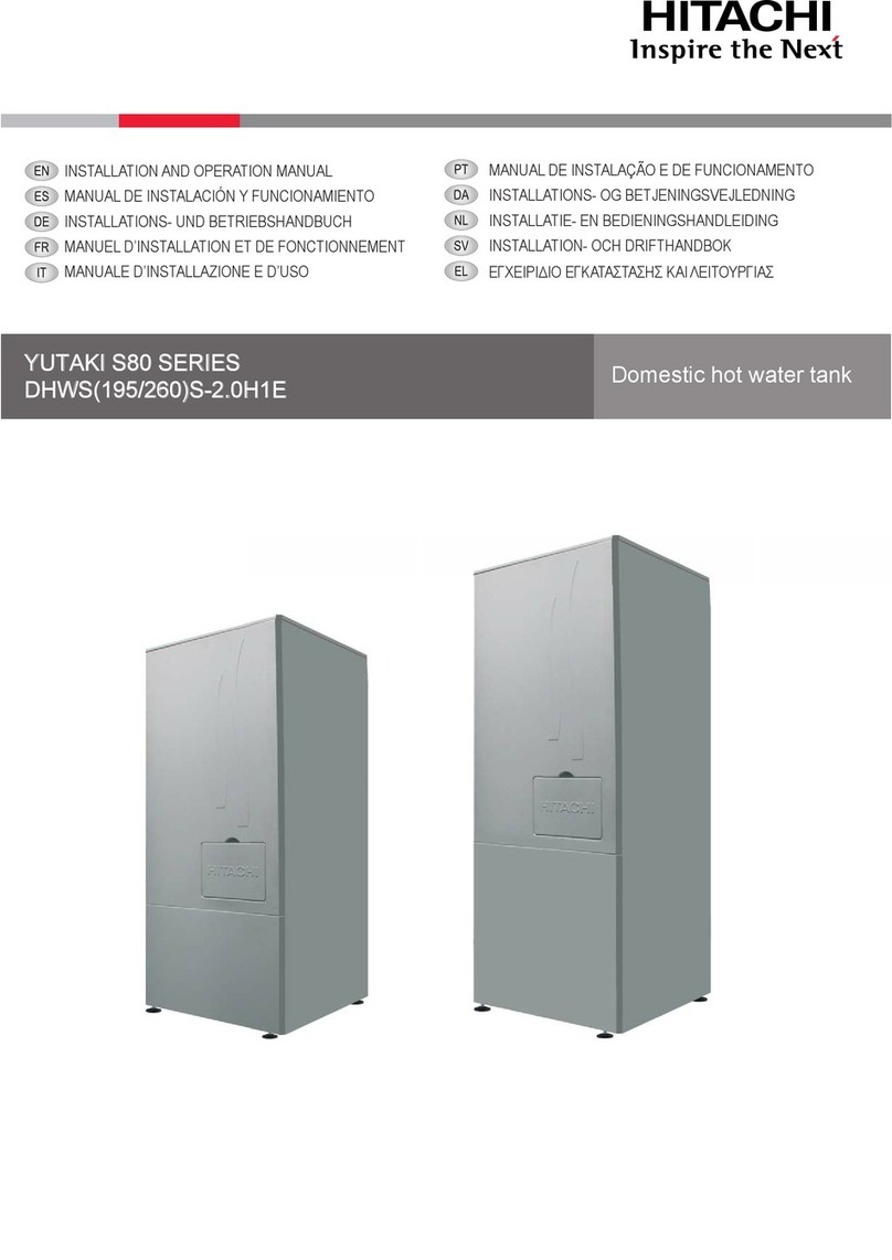
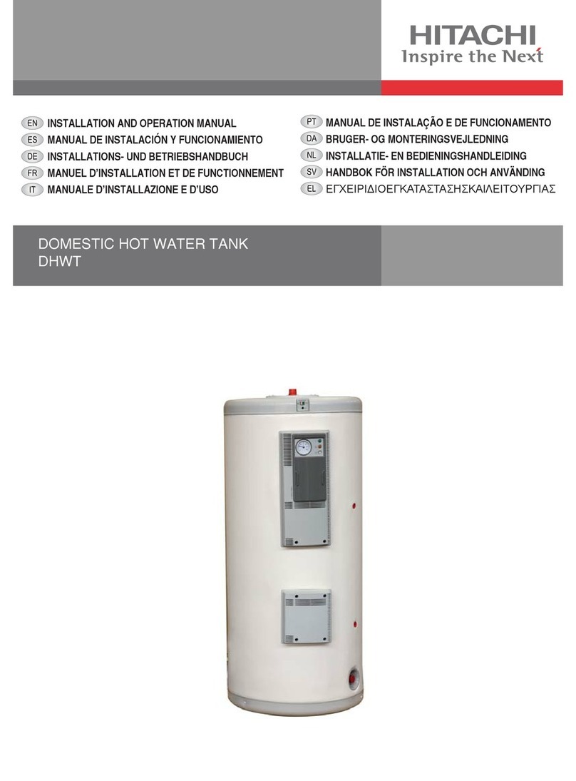
Hitachi WEH-6E User manual

WATER ELECTRIC HEATER FOR YUTAKI SERIES
WEH-6E
INSTALLATION AND OPERATION MANUAL
MANUAL DE INSTALACIÓN Y FUNCIONAMIENTO
INSTALLATIONS- UND BETRIEBSHANDBUCH
MANUEL D’INSTALLATION ET DE FONCTIONNEMENT
MANUALE D’INSTALLAZIONE E D’USO
MANUAL DE INSTALAÇÃO E DE FUNCIONAMENTO
INSTALLATIONS- OG BETJENINGSVEJLEDNING
INSTALLATIE- EN BEDIENINGSHANDLEIDING
INSTALLATION- OCH DRIFTHANDBOK
ΕΓΧΕΙΡΙΔΙΟ ΕΓΚΑΤΑΣΤΑΣΗΣ ΚΑΙ ΛΕΙΤΟΥΡΓΙΑΣ


English
Specications in this manual are subject to change without notice in order that HITACHI may bring the latest innovations
to their customers.
Whilst every effort is made to ensure that all specications are correct, printing errors are beyond Hitachi’s control;
Hitachi cannot be held responsible for these errors.
Español
Las especicaciones de este manual están sujetas a cambios sin previo aviso a n de que HITACHI pueda ofrecer las
últimas innovaciones a sus clientes.
A pesar de que se hacen todos los esfuerzos posibles para asegurarse de que las especicaciones sean correctas, los
errores de impresión están fuera del control de HITACHI, a quien no se hará responsable de ellos.
Deutsch
Bei den technischen Angaben in diesem Handbuch sind Änderungen vorbehalten, damit HITACHI seinen Kunden die
jeweils neuesten Innovationen präsentieren kann.
Sämtliche Anstrengungen wurden unternommen, um sicherzustellen, dass alle technischen Informationen ohne Fehler
veröffentlicht worden sind. Für Druckfehler kann HITACHI jedoch keine Verantwortung übernehmen, da sie außerhalb
ihrer Kontrolle liegen.
Français
Les caractéristiques publiées dans ce manuel peuvent être modiées sans préavis, HITACHI souhaitant pouvoir toujours
offrir à ses clients les dernières innovations.
Bien que tous les efforts sont faits pour assurer l’exactitude des caractéristiques, les erreurs d’impression sont hors du
contrôle de HITACHI qui ne pourrait en être tenu responsable.
Italiano
Le speciche di questo manuale sono soggette a modica senza preavviso afnché HITACHI possa offrire ai propri
clienti le ultime novità.
Sebbene sia stata posta la massima cura nel garantire la correttezza dei dati, HITACHI non è responsabile per eventuali
errori di stampa che esulano dal proprio controllo.
Português
As especicações apresentadas neste manual estão sujeitas a alterações sem aviso prévio, de modo a que a HITACHI
possa oferecer aos seus clientes, da forma mais expedita possível, as inovações mais recentes.
Apesar de serem feitos todos os esforços para assegurar que todas as especicações apresentadas são correctas,
quaisquer erros de impressão estão fora do controlo da HITACHI, que não pode ser responsabilizada por estes erros
eventuais.
Dansk
Specikationerne i denne vejledning kan ændres uden varsel, for at HITACHI kan bringe de nyeste innovationer ud til
kunderne.
På trods af alle anstrengelser for at sikre at alle specikationerne er korrekte, har Hitachi ikke kontrol over trykfejl, og
Hitachi kan ikke holdes ansvarlig herfor.
Nederlands
De specicaties in deze handleiding kunnen worden gewijzigd zonder verdere kennisgeving zodat HITACHI zijn klanten
kan voorzien van de nieuwste innovaties.
Iedere poging wordt ondernomen om te zorgen dat alle specicaties juist zijn. Voorkomende drukfouten kunnen echter
niet door Hitachi worden gecontroleerd, waardoor Hitachi niet aansprakelijk kan worden gesteld voor deze fouten.
Svenska
Specikationerna i den här handboken kan ändras utan föregående meddelande för att HITACHI ska kunna leverera de
senaste innovationerna till kunderna.
Vi på Hitachi gör allt vi kan för att se till att alla specikationer stämmer, men vi har ingen kontroll över tryckfel och kan
därför inte hållas ansvariga för den typen av fel.
Eλλhnika
Οι προδιαγραφές του εγχειριδίου μπορούν να αλλάξουν χωρίς προειδοποίηση, προκειμένου η HITACHI να παρέχει τις
τελευταίες καινοτομίες στους πελάτες της.
Αν και έχει γίνει κάθε προσπάθεια προκειμένου να εξασφαλιστεί ότι οι προδιαγραφές είναι σωστές, η Hitachi δεν μπορεί
να ελέγξει τα τυπογραφικά λάθη και, ως εκ τούτου, δεν φέρει καμία ευθύνη για αυτά τα λάθη.

!CAUTION
This product shall not be mixed with general house waste at the end of its life and it shall be retired according to the
appropriated local or national regulations in a environmentally correct way.
Due to the refrigerant, oil and other components contained in Air Conditioner, its dismantling must be done by a professio-
nal installer according to the applicable regulations. Contact to the corresponding authorities for more information.
!PRECAUCIÓN
Éste producto no se debe eliminar con la basura doméstica al nal de su vida útil y se debe desechar de manera respetuosa con el
medio ambiente de acuerdo con los reglamentos locales o nacionales aplicables.
Debido al refrigerante, el aceite y otros componentes contenidos en el sistema de aire acondicionado, su desmontaje debe realizarlo un
instalador profesional de acuerdo con la normativa aplicable. Para obtener más información, póngase en contacto con las autoridades
competentes.
!VORSICHT
Dass Ihr Produkt am Ende seiner Betriebsdauer nicht in den allgemeinen Hausmüll geworfen werden darf, sondern entsprechend den
geltenden örtlichen und nationalen Bestimmungen auf umweltfreundliche Weise entsorgt werden muss.
Aufgrund des Kältemittels, des Öls und anderer in der Klimaanlage enthaltener Komponenten muss die Demontage von einem
Fachmann entsprechend den geltenden Vorschriften durchgeführt werden. Für weitere Informationen setzen Sie sich bitte mit den
entsprechenden Behörden in Verbindung.
!ADVERTISSEMENT
Ne doit pas être mélangé aux ordures ménagères ordinaires à la n de sa vie utile et qu’il doit être éliminé conformément à la réglemen-
tation locale ou nationale, dans le plus strict respect de l’environnement.
En raison du frigorigène, de l’huile et des autres composants que le climatiseur contient, son démontage doit être réalisé par un installa-
teur professionnel conformément aux réglementations en vigueur.
!AVVERTENZE
Indicazioni per il corretto smaltimento del prodotto ai sensi della Direttiva Europea 2002/96/EC e Dlgs 25 luglio 2005 n.151
Il simbolo del cassonetto barrato riportato sull’ apparecchiatura indica che il prodotto alla ne della propria vita utile deve essere raccolto
separatamente dagli altri riuti.
L’utente dovrà, pertanto, conferire l’apparecchiatura giunta a ne vita agli idonei centri di raccolta differenziata dei riuti elettronici ed
elettrotecnici, oppure riconsegnarla al rivenditore al momento dell’ acquisto di una nuova apparecchiatura di tipo equivalente.
L’adeguata raccolta differenziata delle apparecchiature dismesse, per il loro avvio al riciclaggio, al trattamento ed allo smaltimento
ambientalmente compatibile, contribuisce ad evitare possibili effetti negativi sull’ ambiente e sulla salute e favorisce il riciclo dei materiali
di cui è composta l’ apparecchiatura. Non tentate di smontare il sistema o l’unità da soli poichè ciò potrebbe causare effetti dannosi sulla
vostra salute o sull’ ambiente. Vogliate contattare l’ installatore, il rivenditore, o le autorità locali per ulteriori informazioni.
Lo smaltimento abusivo del prodotto da parte dell’utente può comportare l’applicazione delle sanzioni amministrative di cui all’articolo 50
e seguenti del D.Lgs. n. 22/1997.
!CUIDADO
O seu produto não deve ser misturado com os desperdícios domésticos de carácter geral no nal da sua duração e que deve ser elimi-
nado de acordo com os regulamentos locais ou nacionais adequados de uma forma correcta para o meio ambiente.
Devido ao refrigerante, ao óleo e a outros componentes contidos no Ar condicionado, a desmontagem deve ser realizada por um insta-
lador prossional de acordo com os regulamentos aplicáveis. Contacte as autoridades correspondentes para obter mais informações.
!ADVASEL!
At produktet ikke må smides ud sammen med almindeligt husholdningsaffald, men skal bortskaffes i overensstemmelse med de
gældende lokale eller nationale regler på en miljømæssig korrekt måde.
Da klimaanlægget indeholder kølemiddel, olie samt andre komponenter, skal afmontering foretages af en fagmand i overenss-
temmelse med de gældende bestemmelser.
Kontakt de pågældende myndigheder for at få yderligere oplysninger.
!VOORZICHTIG
Dit houdt in dat uw product niet wordt gemengd met gewoon huisvuil wanneer u het weg doet en dat het wordt gescheiden op een
milieuvriendelijke manier volgens de geldige plaatselijke en landelijke reguleringen.
Vanwege het koelmiddel, de olie en andere onderdelen in de airconditioner moet het apparaat volgens de geldige regulering door een
professionele installateur uit elkaar gehaald worden. Neem contact op met de betreffende overheidsdienst voor meer informatie.
!FÖRSIKTIGHET
Det innebär att produkten inte ska slängas tillsammans med vanligt hushållsavfall utan kasseras på ett miljövänligt sätt i enlighet med
gällande lokal eller nationell lagstiftning.
Luftkonditioneringsaggregatet innehåller kylmedium, olja och andra komponenter, vilket gör att det måste demonteras av en fackman i
enlighet med tillämpliga regelverk.
Ta kontakt med ansvarig myndighet om du vill ha mer information.
!ΠΡΟΣΟΧΗ
Σημαίνει ότι το προϊόν δεν θα πρέπει να αναμιχθεί με τα διάφορα οικιακά απορρίμματα στο τέλος του κύκλου ζωής του και θα πρέπει να
αποσυρθεί σύμφωνα με τους κατάλληλους τοπικούς ή εθνικούς κανονισμούς και με τρόπο φιλικό προς το περιβάλλον.
Λόγω του ψυκτικού, του λαδιού και άλλων στοιχείων που περιέχονται στο κλιματιστικό, η αποσυναρμολόγησή του πρέπει να γίνει από
επαγγελματία τεχνικό και σύμφωνα με τους ισχύοντες κανονισμούς.
Για περισσότερες λεπτομέρειες, επικοινωνήστε με τις αντίστοιχες αρχές.

!
DANGER – Hazards or unsafe practices which COULD result in severe personal injuries or death.
PELIGRO – Riesgos o prácticas poco seguras que PODRÍAN producir lesiones personales e incluso la muerte.
GEFAHR – Gefährliche oder unsichere Anwendung, die zu schweren Körperverletzungen oder zum Tod führen kann.
DANGER – Utilisation dangereuse ou sans garantie de sécurité qui PEUT provoquer de sévères blessures personnelles ou la mort.
PERICOLO – Pericoli o azioni pericolose che POTREBBERO avere come esito lesioni siche gravi o il decesso.
PERIGO – Riesgos o prácticas poco seguras que PUEDEN producir lesiones personales e incluso la muerte
FARE – Farer eller farlig brug, som KAN resultere i alvorlig personskade eller dødsfald.
GEVAAR – Gevaren of onveilige praktijken die ernstig persoonlijk letsel of de dood tot gevolg KUNNEN hebben.
FARA – Risker eller osäkra tillvägagångssätt som KAN leda till svåra personskador eller dödsfall.
KINAYNO – Κίνδυνοι ή επικίνδυνες πρακτικές, οι οποίες ΜΠΟΡΕΙ να έχουν ως αποτέλεσµα σοβαρές σωµατικές βλάβες ή θάνατο.
!
CAUTION – Hazards or unsafe practices which COULD result in minor personal injury or product or property damage.
PRECAUCIÓN – Riesgos o prácticas poco seguras que PODRÍAN provocar lesiones personales de menor importancia o daños en el
producto u otros bienes.
VORSICHT – Gefährliche oder unsichere Anwendung, die geringfügigen Personen-, Produkt- oder Sachschaden verursachen kann.
PRECAUTION – Utilisation dangereuse ou sans garantie de sécurité qui PEUT provoquer des blessures mineures ou des dommages
au produit ou aux biens.
ATTENZIONE – Pericoli o azioni pericolose che POTREBBERO avere come esito lesioni siche minori o danni al prodotto o ad altri
beni.
CUIDADO – Perigos e procedimentos perigosos que PODERÃO PROVOCAR danos pessoais ligeiros ou danos em produtos e bens.
FORSIGTIG – Farer eller farlig brug, som KAN resultere i mindre skade på personer, produkt eller ejendom.
LET OP – Gevaren of onveilige praktijken die licht persoonlijk letsel of beschadiging van het product of eigendommen tot gevolg
KUNNEN hebben.
VARSAMHET – Risker eller farliga tillvägagångssätt som KAN leda till mindre personskador eller skador på produkten eller på
egendom.
ΠΡΟΣΟΧΗ – Κίνδυνοι ή επικίνδυνες πρακτικές, οι οποίες ΜΠΟΡΕΙ να έχουν ως αποτέλεσµα την πρόκληση ελαφρών σωµατικών
βλαβών ή καταστροφή περιουσίας.
?
NOTE – The text following this symbol contains information or instructions that may be of use or that require a more thorough
explanation.
NOTA – El texto que sigue a este símbolo contiene información o instrucciones que pueden ser de utilidad o requeridas para ampliar
una explicación.
HINWEIS – Der diesem Symbol folgende Text enthält konkrete Informationen und Anleitungen, die nützlich sein können oder eine
tiefergehende Erklärung benötigen.
REMARQUE – Les textes précédés de ce symbole contiennent des informations ou des indications qui peuvent être utiles, ou qui
méritent une explication plus étendue.
NOTA – I testi preceduti da questo simbolo contengono informazioni o indicazioni che possono risultare utili o che meritano una
spiegazione più estesa.
NOTA – Os textos precedidos deste símbolo contêm informações ou indicações que podem ser úteis, ou que merecem uma explicação
mais detalhada.
BEMÆRK – Den tekst, der følger efter dette symbol, indeholder oplysninger eller anvisninger, der kan være til nytte, eller som kræver
en mere grundig forklaring.
OPMERKING – De teksten waar dit symbool voorstaat bevatten nuttige informatie en aanwijzingen, of informatie en aanwijzingen meer
uitleg behoeven.
OBS – Texten efter denna symbol innehåller information och anvisningar som kan vara användbara eller som kräver en noggrannare
förklaring.
ΣΗΜΕΙΩΣΗ – Το κείμενο που ακολουθεί αυτό το σύμβολο περιέχει πληροφορίες ή οδηγίες που μπορεί να φανούν χρήσιμες ή που
απαιτούν μια πιο ενδελεχή εξήγηση.


INDEX
1 SYSTEM DESCRIPTION
2 SAFETY SUMMARY
3 IMPORTANT NOTICE
4 BEFORE OPERATION
5 AUTOMATIC CONTROLS
6 BASIC TROUBLESHOOTING
7 NAME OF PARTS
8 UNIT INSTALLATION
9 HYDRAULIC CIRCUIT
10 ELECTRICAL WIRING
11 SAFETY SUMMARY & CONTROL DEVICE SETTING
ÍNDICE
1 DESCRIPCIÓN DEL SISTEMA
2 RESUMEN DE SEGURIDAD
3 AVISO IMPORTANTE
4 ANTES DEL FUNCIONAMIENTO
5 CONTROLES AUTOMÁTICOS
6 RESOLUCIÓN DE PROBLEMAS BÁSICOS
7 NOMBRES DE LAS PIEZAS
8 INSTALACIÓN DE LA UNIDAD
9 CIRCUITO HIDRÁULICO
10 CABLEADO ELÉCTRICO
11 RESUMEN DE SEGURIDAD Y AJUSTE DE LOS
DISPOSITIVOS DE CONTROL
INHALTSVERZEICHNIS
1 SYSTEMBESCHREIBUNG
2 SICHERHEITSÜBERSICHT
3 WICHTIGER HINWEIS
4 VOR DEM BETRIEB
5 AUTOMATISCHE STEUERUNGEN
6 GRUNDLEGENDE FEHLERBEHEBUNG
7 TEILEBEZEICHNUNG
8 GERÄTEINSTALLATION
9 HYDRAULIKKREISLAUF
10 KABELANSCHLUSS
11 SICHERHEITSÜBERSICHT &
STEUERUNGSEINSTELLUNGEN
INDEX
1 DESCRIPTION DU SYSTÈME
2 CONSIGNES DE SÉCURITÉ
3 REMARQUES IMPORTANTES
4 AVANT L’UTILISATION
5 CONTRÔLES AUTOMATIQUES
6 DÉPANNAGE DE BASE
7 NOMENCLATURE DES PIÈCES
8 INSTALLATION DES UNITES
9 CIRCUIT HYDRAULIQUE
10 CABLAGE ELECTRIQUE
11 SOMMAIRE DES DISPOSITIFS DE SÉCURITÉ ET
RÉGLAGE DES ORGANES DE CONTRÔLE
INDICE
1 DESCRIZIONE DEL SISTEMA
2 PRECAUZIONI PER LA SICUREZZA
3 NOTA IMPORTANTE
4 PROCEDURA PRELIMINARE
5 CONTROLLI AUTOMATICI
6 RISOLUZIONE DEI PROBLEMI
7 NOMENCLATURA DEI COMPONENTI
8 INSTALLAZIONE DELL’UNITÀ
9 CIRCUITO IDRAULICO
10 COLLEGAMENTI ELETTRICI
11 RIEPILOGO DELLE IMPOSTAZIONI DEI DISPOSITIVI DI
CONTROLLO E SICUREZZA
ÍNDICE
1 DESCRIÇÃO DO SISTEMA
2 RESUMO DA SEGURANÇA
3 NOTA IMPORTANTE
4 ANTES DE ARRANCAR A UNIDADE
5 CONTROLOS AUTOMÁTICOS
6 RESOLUÇÃO DE PROBLEMAS BÁSICOS
7 NOME DAS
PEÇAS
8 INSTALAÇÃO DA UNIDADE
9 CIRCUITO HIDRÁULICO
10 LIGAÇÕES ELÉCTRICAS
11 SUMÁRIO DE SEGURANÇA E AJUSTE DE DISPOSITIVO
DE CONTROLO
INDHOLDSFORTEGNELSE
1 SYSTEM BESKRIVELSE
2 OVERSIGT OVER SIKKERHED
3 VIGTIG MEDDELELSE
4 FØR DRIFT
5 AUTOMATISKE KONTROLLE
6 BASIS FEJLFINDING
7 NAVN PÅ DELE
8 MONTERING AF ENHED
9 HYDRAULISK KREDSLØB
10 ELEKTRISK LEDNINGSFØRING
11 OVERSIGT OVER INDSTILLINGER FOR SIKKERHEDS-OG
KONTROLENHEDER
INHOUDSOPGAVE
1 BESCHRIJVING VAN HET SYSTEEM
2 OVERZICHT VEILIGHEID
3 BELANGRIJKE MEDEDELING
4 VOORDAT U HET SYSTEEM IN GEBRUIK NEEMT
5 AUTOMATISCHE BESTURING
6 ELEMENTAIRE PROBLEMEN OPLOSSEN
7 NAMEN VAN ONDERDELEN
8 INSTALLATIE VAN DE UNIT
9 HYDRAULISCH CIRCUIT
10 ELEKTRISCHE BEDRADING
11 OVERZICHT VEILIGHEID & BESTURINGSINRICHTING
INNEHALLSFÖRTECKNING
1 SYSTEMÖVERSIKT
2 SÄKERHETSSAMMANFATTNING
3 VIKTIG ANMÄRKNING
4 FÖRE DRIFT
5 AUTOMATISKA KONTROLLER
6 FELSÖKNING
7 DELAR
8 INSTALLATION AV ENHET
9 HYDRAULISK KRETS
10 ELEKTRISKA LEDNINGAR
11 SÄKERHETSFÖRESKRIFTER OCH
SÄKERHETSINSTÄLLNINGAR
ΕΥΡΕΤΗΡΙΟ
1 ΠΕΡΙΓΡΑΦΗ ΤΟΥ ΣΥΣΤΗΜΑΤΟΣ
2 ΣΥΝΟΠΤΙΚΕΣ ΠΡΟΦΥΛΑΞΕΙΣ ΑΣΦΑΛΕΙΑΣ
3 ΣΗΜΑΝΤΙΚΗ ΠΑΡΑΤΗΡΗΣΗ
4 ΠΡΙΝ ΤΗ ΛΕΙΤΟΥΡΓΙΑ
5 ΑΥΤΟΜΑΤΕΣ ΛΕΙΤΟΥΡΓΙΕΣ
6 ΑΝΤΙΜΕΤΩΠΙΣΗ ΒΑΣΙΚΩΝ ΠΡΟΒΛΗΜΑΤΩΝ
7 ΟΝΟΜΑΤΑ ΕΞΑΡΤΗΜΑΤΩΝ
8 ΕΓΚΑΤΑΣΤΑΣΗ ΜΟΝΑΔΩΝ
9 ΥΔΡΑΥΛΙΚΟ ΚΥΚΛΩΜΑ
10 ΗΛΕΚΤΡΙΚΗ ΚΑΛΩΔΙΩΣΗ
11 ΣΥΝΟΠΤΙΚΕΣ ΠΡΟΦΥΛΑΞΕΙΣ ΑΣΦΑΛΕΙΑΣ & ΡΥΘΜΙΣΕΙΣ
ΣΥΣΚΕΥΩΝ ΕΛΕΓΧΟΥ


ENGLISH
PART I - OPERATION
1 SYSTEM DESCRIPTION
Water Electric Heater
Position-separating hyphen (xed)
Heater power (kW)
Made in Europe
WEH - 6 E
1.1 “MONO-ENERGY” SYSTEMS
The YUTAKI system is designed to provide around 60% of the
heating capacity for the coldest day of the year, and to provide
90-95% of the capacity required throughout the entire heating
season. An auxiliary electrical resistance will be responsible for
providing the rest of the caloric energy on the coldest days.
This is one of the most common systems since it gives the right
balance between operating and investment costs.
It is usually used for new systems or when traditional boilers are
replaced.
Single-energy system
(YUTAKI Unit + electric heater)
Coldest day of the year
(A)
(B)
Capacity of
YUTAKI unit
90%
Required heating
Hours
Point of
equilibrium
(C)
10%
Heating load
demanded:
?NOTE
• (A) Excess capacity on the YUTAKI M or S80 unit
• (B) Capacity covered by the YUTAKI M or S80 unit
• (C) Capacity covered by the electric heater
Example for YUTAKI M:
SYSTEM DESCRIPTION
PMML0199A rev.4 - 12/2016
1

2 SAFETY SUMMARY
!DANGER
• Do not pour water inside electrical box of WEH. These products are
equipped with electrical parts. If water contacts with electrical compo-
nents then it will cause a serious electrical shock.
• Do not touch or adjust safety devices inside WEH. If these devices
are touched or adjusted, it should cause a serious accident.
• Do not open the electrical box or access inside WEH without discon-
necting the main power supply.
• In case of re Turn OFF the main switch and carry out the necessary
actions to extinguish the re at once. In that case contact your service
contractor.
• It must ensured that WEH cannot operate accidentally without water
neither with air inside hydraulic system.
!CAUTION
• This appliance must be used only by adult and capable people, hav-
ing received the technical information or instructions to handle prop-
erly and safely this appliance.
• Children should be supervised to ensure that they do not play with
the appliance.
• Do not use any sprays such as insecticide, lacquer, hair spray or oth-
er ammable gases within approximately one meter from the system.
• If circuit breaker or fuse is often activated, stop the system and con-
tact your service contractor.
• Do not make service or inspections tasks by yourself. This work must
be performed by qualied service person.
• Do not put any strange material (sticks, etc...) into the water inlet and
outlet piping
3 IMPORTANT NOTICE
• Verify in accordance with the manual that all the information
required for the correct installation of the system is included.
If this is not the case, contact your distributor.
• HITACHI pursues a policy of continuing improvement in
design and performance of products. The right is therefore
reserved to vary specications without notice.
• HITACHI cannot anticipate every possible circumstance that
might involve a potential hazard.
• This WEH has been designed for standard water heating for
human beings only. Do not use this for other purposes such
as for drying clothes, heating foods or for any other heating
process.
• No part of this manual should be reproduced without written
permission.
• If you have any questions, contact your service contractor of
HITACHI.
• Check and make sure that the explanations of each part of
this manual correspond to your WEH model.
• Signal words (DANGER, CAUTION and NOTE) are used
to identify levels of hazard seriousness. Denitions for
identifying hazard levels are provided below with their
respective signal words.
• It is assumed that this unit will be operated and serviced by
people speaking some of the languages used in this Manual.
If this is not the case, the customer should add safety,
caution and operating signs in the native language of the
personal.
• This WEH has been designed for the following water
temperatures. Operate the WEH within this range:
Min. Max.
Operating Temperature Out of Freeze 75ºC
• This manual should be considered as a permanent part
of the WEH. This manual gives a common description and
information for this WEH.
!DANGER
This WEH is protected from abnormal low water pressures by an
internal applied low water pressure switch. However, if abnormally
high pressure is applied to the WEH, it might result in serious injury
due to explosion of the pressure vessel. Do not apply this WEH in
water systems with a water pressure out of the WEH water pressure
range. If necessary, apply a high pressure switch to protect it in ac-
cordance to local codes.
Min. Max.
Operating Pressure 0.1 MPa 0.5 MPa
?NOTE
The Low Water Pressure Switch is indicated on the electrical wiring dia-
gram in the WEH unit as LWPS.
• Do not change the LWPS switch locally or change the
pressure cut-out set value locally. If changed, it might cause
serious injury or death due to asphyxia caused by smoke.
SAFETY SUMMARY
PMML0199A rev.4 - 12/2016
2

ENGLISH
4 BEFORE OPERATION
!CAUTION:
• Turn OFF the main switch when the system must be stopped for a long time period.
• Check that there is no water leakage.
• Ensure that pressure inside the WEH is not higher than 3 bars.
• Ensure that the WEH is never accidentally operated before water pumps is activated.
• Ensure that the WEH is never accidentally stopped later than water pump switch off.
5 AUTOMATIC CONTROLS
The heater operation is controlled by the YUTAKI System Control. Heat demand is calculated by a P+I control inside Control System
which switch ON and OFF WEH in 3 steps as shows following table (for more detail see YUTAKI Service Manual):
Regulation step R1 - Electric
resistance 1
R2 - Electric
resistance 2
R3 - Electric
resistance 3 Total power
Step 0: OFF OFF OFF 0 kW
Step 1: ON OFF OFF 2 kW
Step 2: OFF ON ON 4 kW
Step 3: ON ON ON 6 kW
6 BASIC TROUBLESHOOTING
!CAUTION
• When water leakage occurs, stop the operation and contact your contractor.
• When you smell or white smoke occurs from the WEH, stop the system and contact your contractor.
No operation
• Check whether the SET TEMPERATURE is set at the correct temperature.
• Check electrical connection from YUTAKI and WEH (Fuse or Circuit Breaker operation)
• Check Water Temperature and possible Thermostat Cut-Out activation (if higher than 85ºC > thermostat Cut-Out)
• Check Water Pressure and Water Flow (at least 0,1MPa.)
Not heating well
• Check for obstruction of water ow inside Water Circuit.
• Check if the water pressure conditions is not within the operating range.
• Check electrical connection from YUTAKI and WEH.
• In case of non-functioning heater should be checked.
If trouble still remains...
If the trouble still remains even after checking the above items, contact your service contractor and inform the following data:
• Unit Model Name
• Trouble description
BEFORE OPERATION
PMML0199A rev.4 - 12/2016
3

PART II - INSTALLATION
7 NAME OF PARTS
Ref. Qty. Name
1 Tank body
1 Front E-casing
1 Back E-casing
1 Tank in-connection
1 Wall support
1 Tank front cover
1 Tank out-connection
1 Resistance
1 Tank body insulation
Ref. Qty. Name
1PSW
2 3-pole contactor
1 Thermostat
1 Terminal board
1 Packing gland
2 Packing gland
1 PSW protector
1 Caution label
1 Indication poster
1 Wiring label
8 UNIT INSTALLATION
Transport the products as close as possible to the installation location before unpacking.
Check the contents of the package:
• WEH-6E
• Installation and Operation Manual
• (2) M6x15 screw and (2) M6 washers
• Wall xing support
8.1 SELECTION PROCEDURE FOR YUTAKI UNITS
!CAUTION
• WEH appliance is intended to be installed in an indoor place.
• WEH installation must be done by professional installers.
• Install the WEH with sufcient clearance around it for operation and maintenance as shown in the following gures.
• Install the WEH where good ventilation is available. Do not install the WEH where there is a high level of oil mist, salty air or sulphurous atmosphere.
• Working with no sufcient ventilation, in an enclosed space, should cause oxygen deciency. Toxic gas should be produced when cleaning agent
is heated to high temperature by, e.g., being exposed to re.
• Do not install WEH near any ammable substance.
• When installing some device next to WEH, keep clearance between WEH and any other obstacle of more than 500mm.
NAME OF PARTS
PMML0199A rev.4 - 12/2016
4

ENGLISH
8.2 PLACE PROVISION
Drill 2 holes Ø 8mm on the wall for xing WEH according to the dimensions of the Wall Support attached.
• Fixed supplied support to the wall by using previous drill holes.
• Use attached screws for xing WEH to the supplied support.
• Check that WEH are installed horizontally.
• For cleaning, use non ammable and non toxic cleaning liquid. The use of ammable agents should cause explosion or re.
• Cleaning liquid shall be collected after cleaning.
• Pay attention do not trapp cables when closing the electrical box cover. It could cause a electric shock.
9 HYDRAULIC CIRCUIT
9.1 GENERAL NOTES
When Piping connections are performed:
1 Connect all pipes as close as possible to the unit, so that
disconnection can be easily performed when required.
2 It is recommended to use exible joints for the piping of water
inlet and outlet, so vibration will not be transmitted.
3 Whenever possible, sluice valves should be installed for
water piping, in order to minimise ow resistance and to
maintain sufcient water ow.
4 It is recommended to apply ball valves in both water pipe
connections to make easier any maintenance work.
5 Proper inspection should be performed to check for leaking
parts inside and outside the system, by completely opening
the hot water inlet and outlet valves to the water condenser.
6 This WEH must be fully air purged to avoid heating elements
radiating the tank case without water.
Install WEH as shows on the following drawing in order to
allow a natural purge on the WEH (inlet pipe in the bottom
side, and outlet pipe in the upper side, both vertically
oriented).
It is recommended to install an air purge after outlet piping in
the highest position of the hydraulic installation.
Previous recommendation is a must when there are other
parts of hydraulic system that could be installed in a higher
position than WEH.
7 Apply thermal insulation on the hydraulic system pipes in
order to avoid accidental injure due to excessive heat on
piping surfaces and also to avoid heat losses.
8 When the unit is stopped during shutdown periods and
the ambient temperature is very low, it is possible that the
water in the pipes and in the circulating pump freeze, thus
damaging the pipes and the water pump.
In order to prevent this, during shutdown periods it is useful to
empty the water from the installation.
?NOTE
• In cases where water drainage is difcult, an antifreeze mixture of gly-
col (ethylene or propylene) should be used (content between 10 % and
40 %).(Only for YUTAKI M).
• The performance of the unit working with glycol may decrease in pro-
portion to the percentage of glycol used, since the density of glycol is
higher than that of water.
HYDRAULIC CIRCUIT
PMML0199A rev.4 - 12/2016
5

1G” Water OUT
Water IN 1G”
1/4G”
Inlet and outlet connection pipes must be 1G”
It must be kept the water ow direction indicated in previous drawing
?NOTE
Check periodically:
• Water ow and pressure
• Water leakages
• Fixing points tightening
9.2 MINIMUM WATER VOLUME DESCRIPTION
Necessity of water in system
The following problems should occur when the quantity of water in the forced circulation system (1) on water side is insufcient.
1 WEH frequently ON/OFF cycles affecting YUTAKI performance.
2 Low temperature in water circulation system at defrosting, which should cause an alarm (freeze protection).
3 LWPS or Cut-Out thermostat activation due to low water pressure (< 1 bar) or due to excessive high water temperature inside
WEH.
?NOTE
Calculate and ensure that the water volume in the system is enough (see YUTAKI product manual for recommendations)
9.3 WATER CONTROL
!CAUTION
• When it is used industrial water inside hydraulic system, it rarely causes deposits of scales or other foreign substances on the equipment. However,
well water or river water should in most cases contain suspended solid matter, organic matter, and scales in great quantities. Therefore, such water
should be subjected to ltration or to a softening treatment with chemicals before application as chilled water.
• It is also necessary to analyse the quality of water by checking pH, electrical conductivity, ammonia ion content, sulphur content, and others. Should
the results of the analysis be not good, the use of industrial water would be recommended.
• (see YUTAKI product manual for recommendations).
HYDRAULIC CIRCUIT
PMML0199A rev.4 - 12/2016
6

ENGLISH
10 ELECTRICAL WIRING
10.1 GENERAL CHECK
1 Ensure that the eld-supplied electrical components (main
power switches, circuit breakers, wires, connectors and wire
terminals) have been properly selected according to the
electrical data indicated. Make sure that they comply with
national and regional electrical codes.
2 Electrical connection must be done by professional installers.
3 Make sure that the power supply voltage is within +/-10% of
the rated voltage.
4 Make sure that power supply has an impedance low enough
to warranty not reduce the starting voltage more than 85% of
the rated voltage.
5 Check that the earth wire is securely connected, tagged and
locked in accordance with national and local codes.
6 Connect a fuse of specied capacity.
7 Check periodically the electrical connection tightening
!CAUTION
• Make sure that screws for terminal block are tightly tightened.
• Protect the wires, pipes, electrical parts, from rats or other small ani-
mals. If not protected, rats should damage unprotected parts, and at
the worst, a re will occur.
• Wrap the accessory packing around the wires, to protect the product
from any condensed water and insects. Tightly secure the wires with
the cord clamp inside the unit.
• Lead the wires avoiding any contact with water piping.
• Wrap the accessory packing around the wires from system controller
!DANGER
• Do not connect or adjust any wiring or connections unless the main
power switch is OFF.
• When there are more than one power switch for ON/OFF, check and
test to ensure that all are turned OFF.
10.2 ELECTRICAL WIRING CONNECTION
The electrical wiring connection between WEH, YUTAKI system controller and the electrical power installation is as follows:
Customer connection:
Power terminals Control terminals
Case 1. Power supply:
1~230 V, 50 Hz
Case 2. Power supply:
3N~400 V, 50 Hz
WEH-6H
Terminal board
YUTAKI
S80/M (TB2)
10.3 WIRE SIZE
Recommended minimum sizes for eld provided wires:
Model Power source Max. current
Power source
cable size
Control cable
size
CB
ELB
(no. poles/A/
mA)
EN60 335-1
EN60 335-1
WEH-6E 1~ 230V 50 Hz
3N~ 400V 50 Hz
30 A
10 A
6 mm2
2.5 mm2
0.75 mm2
0.75 mm2
32A
10A
2/40/30
4/40/30
?NOTE
• Follow local codes and regulations when selecting eld wires, Circuit Breakers and Earth Leakage Breakers.
• Use the wires which are not lighter than the ordinary polychloroprene sheathed exible cord (code designation H05RN-F).
ELECTRICAL WIRING
PMML0199A rev.4 - 12/2016
7

11 SAFETY SUMMARY & CONTROL DEVICE SETTING
Protection:
• Low water pressure switch (LWPS).
• This switch cuts out the operation of the WEH when the water pressure inside hydraulic circuit is below than 1 bar.
• Thermostat cut-out.
• This switch cut out the operation on the WEH when the water temperature inside WEH exceed 85ºC
Model UNITS WEH-6E
Low Water Pressure Switch (LWPS) Automatic Reset
Cut-Out MPa <0.1
Max. working pressure MPa 0.5
Thermostat Manual Reset
Cut-Out ºC 85
Contactors
Current A20 (AC1)
Voltage V 230V
Coil Voltaje V 207~253V
Heating resistances
Electric Power (3 resistances) kW 2.0 (x3)
Voltage V 230 V
Ømm 8
Resistances hole xing are nut “G 2 (brass)
Specic heat load W/cm2 8
Material AISI-316L
Resistance cord Ni-Cr 80/20 Ø 0.45mm
SAFETY SUMMARY & CONTROL DEVICE SETTING
PMML0199A rev.4 - 12/2016
8

1ª PARTE - FUNCIONAMIENTO
1 DESCRIPCIÓN DEL SISTEMA
Calentador eléctrico de agua
Guión separador de posición (jo)
Potencia del calentador (kW)
Fabricado en Europa
WEH - 6 E
1.1 SISTEMAS “MONO-ENERGÉTICOS”
El sistema YUTAKI está diseñado para proporcionar un 60%
de capacidad de calefacción para el día más frío del año, y de
proporcionar un 90-95% de la capacidad requerida durante toda
la temporada de calefacción. Una resistencia eléctrica auxiliar
será la responsable de proporcionar el resto de la energía
caloríca en los días más fríos.
Este es uno de los sistemas más comunes dado que proporciona
el balance correcto entre los costes de funcionamiento y la
inversión.
Se usa generalmente para sistemas nuevos o cuando las
calderas tradicionales se sustituyen.
Sistema monoenergético
(Unidad YUTAKI + calentador eléctrico)
El día más frío del año
(A)
(B)
Capacidad
de la unidad
YUTAKI
90%
Calefacción requerida
Horas
Punto de
equilibrio
(C)
10%
Carga de
calefacción
demandada
?NOTA
• (A) Capacidad excedida en la unidad YUTAKI M o S80
• (B) Capacidad cubierta por la unidad YUTAKI M o S80
• (C) Capacidad cubierta por el calentador eléctrico
Ejemplo para YUTAKI M:
DESCRIPCIÓN DEL SISTEMA
PMML0199A rev.4 - 12/2016
9
ESPAÑOL

2 RESUMEN DE SEGURIDAD
!PELIGRO
• No vierta agua dentro de la caja eléctrica del WEH. Estos pro-
ductos están equipados con piezas eléctricas. Si el agua entra
en contacto con los componentes eléctricos, se producirá una
descarga eléctrica grave.
• No toque ni ajuste los dispositivos dentro del WEH. Si estos dis-
positivos se tocan o ajustan, se podría provocar un accidente
grave.
• No abra la caja eléctrica ni acceda al interior del WEH sin
desconectar la fuente de alimentación principal.
• En caso de fuego Apague el interruptor principal y lleve a cabo
las medidas necesarias para apagar el fuego inmediatamente.
En ese caso, póngase en contacto con el proveedor de servi-
cios.
• Se debe asegurar de que el WEH no puede funcionar accidental-
mente sin agua o con aire dentro del sistema hidráulico.
!PRECAUCIÓN
• Este dispositivo debe ser utilizado únicamente por un adulto o por
una persona responsable que haya recibido formación o las instruc-
ciones técnicas de cómo manejar de forma adecuada y segura este
dispositivo.
• Es preciso vigilar a los niños para que no jueguen con el dispositivo.
• No emplee ningún aerosol, como insecticidas, barnices o lacas, ni
ningún otro gas inamable a menos de aproximadamente un metro
del sistema.
• Si el disyuntor o el fusible se activan con frecuencia, detenga el sis-
tema y póngase en contacto con el proveedor de servicios.
• No realice ninguna tarea de mantenimiento ni inspección. Este tra-
bajo debe llevarlo a cabo personal de servicio cualicado.
• No coloque ningún material extraño (palos, etc.) en la tubería de en-
trada ni en la de salida de agua.
3 AVISO IMPORTANTE
• Compruebe en el manual que dispone de toda la información
necesaria para la correcta instalación del sistema. Si no es
así, póngase en contacto con su distribuidor.
• HITACHI sigue una política de continua mejora del diseño
y rendimiento de los productos. Se reserva, por lo tanto, el
derecho a modicar las especicaciones sin previo aviso.
• HITACHI no puede prever todas las circunstancias que
pudieran conllevar un peligro potencial.
• Este WEH se ha diseñado para suministrar agua caliente
únicamente a las personas. No lo emplee para otros nes,
como secar ropa, calentar alimentos o cualquier otro
proceso de calentamiento.
• Ninguna parte de este manual debe reproducirse sin
permiso por escrito.
• Si tiene cualquier tipo de duda, póngase en contacto con el
proveedor de servicios de HITACHI.
• Compruebe y asegúrese de que las explicaciones de los
apartados de este manual se corresponden con el modelo
de WEH del que dispone.
• Se utilizan palabras precedidas de señales (PELIGRO,
PRECAUCIÓN y NOTA) para identicar los niveles de
gravedad de los riesgos. Las deniciones empleadas para
identicar estos niveles se indican a continuación.
• Se asume que esta unidad será manejada y revisada por
personas que hablen alguno de los idiomas que se usan en
este Manual. En caso contrario, el cliente debe incorporar
señales de seguridad, atención y funcionamiento en el
idioma materno del personal.
• Este WEH se ha diseñado para las siguientes temperaturas
de agua. Utilice el WEH dentro de este margen:
Mín. Máx.
Temperatura en
funcionamiento Sin congelación 75 ºC
• Este manual debe considerarse como una parte permanente
del WEH. Este manual proporciona una descripción general
e información para este WEH.
!PELIGRO
Este WEH está protegido de las bajas presiones de agua anómalas
mediante la aplicación de un presostato de baja presión de agua
interno. Sin embargo, si se aplica una presión anómalamente alta
en el WEH, podría provocar graves daños debido a la explosión del
recipiente de presión. No aplique este WEH en los sistemas de agua
con una presión de agua fuera del rango de presión de agua del
WEH. Si fuera necesario, aplique un presostato de alta presión para
protegerlo de acuerdo con los códigos locales.
Mín. Máx.
Presión de funcionamiento 0,1 MPa 0,5 MPa
?NOTA
El Presostato de Baja Presión de Agua se indica en el diagrama del
cableado eléctrico en la unidad del WEH como LWPS.
• No modique localmente el presostato de baja presión de
agua ni la válvula de ajuste de desconexión de la presión.
Si lo hace, podría provocar lesiones graves o la muerte a
causa de la asxia causada por el humo.
RESUMEN DE SEGURIDAD
PMML0199A rev.4 - 12/2016
10

4 ANTES DEL FUNCIONAMIENTO
!PRECAUCIÓN
• Apague el interruptor principal cuando el sistema vaya a permanecer parado durante un largo periodo de tiempo.
• Compruebe que no haya fugas de agua.
• Asegúrese de que la presión dentro del WEH no es superior a 3 bares.
• Asegúrese de que el WEH no funciona nunca de forma accidental antes de que se active la bomba del agua.
• Asegúrese de que el WEH nunca se para de forma accidental después de que la bomba de agua se apaga.
5 CONTROLES AUTOMÁTICOS
El funcionamiento del calentador está controlado por el Control del Sistema YUTAKI. La demanda de calor se calcula mediante un
control P+I dentro del Sistema de Control que ENCIENDE y APAGA el WEH en 3 pasos tal y como se muestra en la siguiente tabla
(para más información consulte el Manual de Servicio de YUTAKI):
Paso de regulación R1 - Resistencia
eléctrica 1
R2 - Resistencia
eléctrica 2
R3 - Resistencia
eléctrica 3 Potencia total
Paso 0: OFF OFF OFF 0 kW
Paso 1: ON OFF OFF 2 kW
Paso 2: OFF ON ON 4 kW
Paso 3: ON ON ON 6 kW
6 RESOLUCIÓN DE PROBLEMAS BÁSICOS
!PRECAUCIÓN
• Cuando se produzca una fuga de agua, detenga el funcionamiento y póngase en contacto con el proveedor.
• Si huele a humo o sale humo blanco del WEH, detenga el sistema y póngase en contacto con el proveedor.
El sistema no funciona
• Compruebe si SET TEMP se encuentra ajustado en la temperatura correcta.
• Compruebe la conexión eléctrica desde la YUTAKI y del WEH (funcionamiento del Fusible o Disyuntor)
• Compruebe la Temperatura del Agua y la posible activación de la Desconexión del Termostato (si fuera mayor que 85 ºC >
Desconexión del termostato)
• Compruebe la Presión y el Caudal de Agua (como mínimo de 0,1 MPa.)
No calienta bien
• Compruebe si hay obstrucciones del caudal de agua dentro del Circuito de Agua.
• Compruebe si las condiciones de presión del agua se encuentran dentro del margen de funcionamiento.
• Compruebe la conexión eléctrica desde la YUTAKI y del WEH.
• En caso de que el calentador no funcione se debe comprobar.
Si el problema persiste…
Si el problema persiste después de llevar a cabo las comprobaciones anteriores, póngase en contacto con su proveedor de
servicios y proporciónele los datos siguientes:
• Nombre del modelo de la unidad
• Descripción del problema
ANTES DEL FUNCIONAMIENTO
PMML0199A rev.4 - 12/2016
11
ESPAÑOL

2ª PARTE: INSTALACIÓN
7 NOMBRES DE LAS PIEZAS
Ref. Cant. Nombre
1 Cuerpo del depósito
1 Frontal de la caja E
1 Parte posterior de la caja E
1 Conexión de entrada del depósito
1 Soporte para pared
1 Tapa frontal del depósito
1 Conexión de salida del depósito
1 Resistencia
1 Aislamiento del cuerpo del depósito
Ref. Cant. Nombre
1PSW
2 Contactor de 3 polos
1 Termostato
1 Cuadro de terminales
1 Prensaestopas
2 Prensaestopas
1 Protector del PSW
1 Etiqueta de precaución
1 Cartel de indicación
1 Etiqueta de cableado
8 INSTALACIÓN DE LA UNIDAD
Traslade los productos lo más cerca posible de la instalación antes de desembalarlos.
Compruebe los contenidos del paquete:
• WEH-6E
• Manual de instalación y funcionamiento
• (2) M6x15 tornillos y (2) M6 arandelas
• Soporte de conexión a la pared
8.1 PROCEDIMIENTO DE SELECCIÓN PARA LAS UNIDADES YUTAKI
!ADVERTENCIA
• El dispositivo WEH está pensado para ser instalado en un lugar en el interior.
• La instalación del WEH debe ser realizada por un instalador profesional.
• Instale el WEH dejando espacio suciente a su alrededor para su manejo y mantenimiento, como se indica en las siguientes
guras.
• Instale el WEH donde exista una buena ventilación. No instale el WEH donde exista un elevado nivel de neblina de aceite o aire
salino, ni en entornos sulfúricos.
• El funcionamiento con una ventilación insuciente, en un espacio cerrado, podría ocasionar una deciencia de oxígeno. Los
gases tóxicos deberían originarse cuando se calienta un agente de limpieza a altas temperaturas como, por ejemplo, cuando se
expone al fuego.
• No instale el WEH cerca de cualquier sustancia inamable.
• Cuando instale algún dispositivo cerca del WEH, deje un espacio de más de 500 mm entre el WEH y cualquier otro obstáculo.
NOMBRES DE LAS PIEZAS
PMML0199A rev.4 - 12/2016
12
Table of contents
Languages:
Other Hitachi Water Heater manuals
Popular Water Heater manuals by other brands

Kenmore
Kenmore 153.337072 owner's manual

Austria Email
Austria Email VACUMAIL series Operating and assembly instructions

PVI Industries
PVI Industries Water Heater user manual

Bradford White
Bradford White Defender RG140T Series Service manual

Daikin
Daikin EKHWS150D3V3 installation manual

STIEBEL ELTRON
STIEBEL ELTRON SNU HOT Operation manual

Hyperion
Hyperion 100 L Installation, operation & maintenance manual

HTP
HTP HPW-50-6 Installation start-up maintenance parts

A.O. Smith
A.O. Smith HSE-SAS user guide

Bosch
Bosch Evolution 500 instruction manual

Noritz
Noritz N-0931M-ASME installation manual

Lochinvar
Lochinvar EFW 85 Installation, Commissioning, User and Maintenance Instructions