Hitex MCB2100 User manual

Quick Start Guide
Hitex Starter Kit for ARM®
with
MCB2100 Evaluation Board
04/2006 - 006 - 5.2 - 30.17.0011.0

© Copyright 2006 Hitex Development Tools GmbH
All rights reserved. No part of this document may be copied or reproduced in any
form or by any means without prior written consent of Hitex Development Tools.
Hitex Development Tools retains the right to make changes to these specifications at
any time, without notice. Hitex Development Tools makes no commitment to update
nor to keep current the information contained in this document.
Hitex Development Tools makes no warranty of any kind with regard to this material,
including, but not limited to, the implied warranties of merchantability and fitness for
a particular purpose. Hitex Development Tools assumes no responsibility for any
errors that may appear in this document.
DProbe, Hitex, HiTOP, Tanto, and Tantino are trademarks of Hitex Development
Tools. All trademarks of other companies used in this document refer exclusively to
the products of these companies.
Hitex Development Tools GmbH
Greschbachstr. 12
D-76229 Karlsruhe
G
ermany
Tel: +49 721 9628 - 0
Fax: +49 721 9628 - 149
Internet: http://www.hitex.de http://www.hitex.com
04/2006 - 006 - 5.2

3
Contents
1 Introduction 5
2 Installing Software and Hardware 6
3 Starting a Project in HiTOP 8
4 The First Steps of Debugging 11
5 Modifying an Application 16
6 Trace Debugging (ETM Support) 16

4 Hitex Starter Kit for ARM®/ MCB2100 Board

Hitex Starter Kit for ARM®/ MCB2100 Board 5
1 Introduction
This starter kit is intended to give a fast introduction into the Philips
LPC2000 ARM microcontroller family, the development of ARM
code and the debugging using the debug hardware Tantino for
ARM 7-9 with HiTOP.
The best way getting started is to follow the instructions of this
small guide.
To get more information about the Hitex Tool chain for ARM, refer
to http://www.hitex.com/perm/arm_toolchain.html.
A comprehensive introduction to the HiTOP5 user interface will be
given in our video tutorials. Feel free to download the movies on
http://www.hitex.com/perm/video_tutorials.html.
We wish you a fast and high quality embedded development using
the Philips LPC2000 microcontroller.
Your Hitex Team

6 Hitex Starter Kit for ARM®/ MCB2100 Board
2 Installing Software and Hardware
Installing the Software
For the installation of HiTOP please insert the CD and follow the
instructions on the screen. If the auto run feature of your CD drive
is disabled, open the CD drive folder and start setup.exe.
Click on
and
and follow the instructions on the screen.
After installing HiTOP, check the jumpers and switches of the
MCB2100 evaluation board.
Now the debug hardware Tantino and the evaluation board may be
installed.

Hitex Starter Kit for ARM®/ MCB2100 Board 7
Installing the Hardware
Tantino for ARM 7-9
•
•
•
Connect the Tantino to the PC's USB port via the USB cable (1).
Connect the 20-pin cable to the board's JTAG connector (2).
Connect the board's power supply (3).
For more details refer to the manual included in the board delivery
package and the Getting Started topic of the Tantino online help.

8 Hitex Starter Kit for ARM®/ MCB2100 Board
3 Starting a Project in HiTOP
Start HiTOP by double clicking the desktop icon:
The tip of the day is presented which contains useful
information when working with HiTOP.
If HiTOP is started for the first time, select the System > Connect
command.
Choose the debugger hardware (Tantino for ARM 7-9 according to
the bottom side label of your Tantino system) and click on Next.
Select as the vendor Philips, as the controller type LPC2129, as
the ARM core type ARM7 and as byte order Little Endian. Click on
Next.
Select as communication port USB and enter the serial number of
your Tantino (without leading zeros).1Click on Connect and
HiTOP will be connected to the Tantino.
If you still have no valid HiTOP license, you will have to fill in the
HiTOP registration dialog.
Now you may load a program into the FLASH or into the RAM. The
project file names show the usage of the memory remapping after
reset.
1The serial number can be found on the down side of the device.

Hitex Starter Kit for ARM®/ MCB2100 Board 9
Starting a FLASH Project
Start the FLASH project using the Project > Open command and
in the ..\Examples\LPC2000\MCB2100\GNU folder, select the
following project file:
Clock_MCB2100_Gnu_Flash.htp
When the Download dialog is presented, click on Ok.
Continue with section Project Loaded (p. 10).
Starting a RAM Project
The RAM project is using only RAM. The necessary remapping
after start will be performed by starting the project.
Start the RAM project using the Project > Open command and in
the ..\Examples\LPC2000\MCB2100\GNU folder, select the
following project file:
Clock_MCB2100_Gnu_RAM.htp
Continue with section Project Loaded (p. 10).

10 Hitex Starter Kit for ARM®/ MCB2100 Board
Project Loaded
After having loaded the project successfully, proceed as follows:
When pressing the target's reset button or performing a target reset
using HiTOP's Debug > Reset command, execute the script file by
clicking on the following toolbar icon:
You may now arrange the windows according to your needs. Note,
that using the View > Save screen layout and View > Load
screen layout commands different window layouts can be stored
and reloaded.1
Do not forget to save the project after such changes (Project > Save).
1More about the handling of HiTOP is shown in the online help system and in the
video tutorials.

Hitex Starter Kit for ARM®/ MCB2100 Board 11
4 The First Steps of Debugging
Now the application is at the starting point ("appl_entry").
If using the flash project, the start address of the FLASH is 0. If
using the RAM project, the start address of the RAM is 0x2000000.
In the Source window, start debugging with some single steps by
clicking on the Step Into icon ,
•
• using the Debug > Step Instruction command, or
• via the F9 function key.
It is also possible to go to a desired code line by moving the cursor
over the window's left side column. The cursor will get a different
shape:
Click on the rectangle using the left mouse button. In the
Disassembly tab of the Source window the code can also be
patched by editing the contents of the instruction column. If the
code is in RAM this is done in the target RAM. If the code is in
FLASH, the patch is performed in a cache.
If the changes shall be programmed into the FLASH please right
click into the Source window and select the context menu's Write
Flash Changes item.

12 Hitex Starter Kit for ARM®/ MCB2100 Board
To start debugging in the main C application you may execute the
application until the function 'main' using
the Go until icon , or
•
• the Debug > Go until dialog (entering 'main').
If the C source file is not opened automatically click on the toolbar's
Show PC icon: (Debug > Show PC Location command).
You can now examine the code and the variables on source level.
Let us now explore the application using breakpoints. The ARM
core has a limited debug functionality which has to be taken into
account during the session, especially when debugging in
ROM/FLASH.
The ARM core has two hardware breakpoint resources. This is why
only two breakpoints (code or data breakpoints) can be set when
debugging in ROM/FLASH. When stepping through the application
or when using a Debug > Go until command, breakpoints are also
used. Trying to set more than two hardware breakpoints in
ROM/FLASH or to step or anything else will cause the following (or
similar) message:
No more breakpoints available
In this case you will have to disable or remove the two breakpoints.
When debugging on RAM, there is an unlimited number of software

Hitex Starter Kit for ARM®/ MCB2100 Board 13
breakpoints and one hardware breakpoint (code breakpoint in ROM
or data breakpoint).1
To show the features of these breakpoints, please do the following.
We are now at the function 'main'. In the workspace window click
on the plus sign ( ) of the 'Clock' module (if it is a minus sign
please skip this action).
Now the symbols of the 'Clock' module are displayed. Click with the
right mouse button on the function 'get_clock' and select the
context menu's Set Breakpoint command.
1This is why ARM recommends to test in RAM.

14 Hitex Starter Kit for ARM®/ MCB2100 Board
After starting emulation by clicking on the Go icon , emulation
will stop at the breakpoint. Open the Source window's context
menu right clicking on the green bar and select Disable
Breakpoint. Mark 'Clock.Sec', 4 lines below the current line with
the mouse, the text 'Clock.Sec' now has a black background
.
Open the Breakpoint window via Debug > Breakpoints and move
it to a position that the marked 'Clock.Sec' can be seen. Now select
the data tab of the Breakpoint window and drag&drop the marked
text into the Breakpoint window. This sets a data breakpoint on a
write access to the 'Sec' element of the 'Clock' structure.
Now, the default setting of this breakpoint has to be modified.
Open the Breakpoint window's context menu right clicking on the
data line and select Change. Click on the Advanced button.
As Type select Byte and as Value Range Minimum enter 10. Close
the dialog clicking on Ok.
In the Watch window, activate another tab than Locals. Drag&drop
the marked 'Clock.Sec' text into the Watch window. The current
value of 'Clock.Sec' is displayed, it should be 0.
Hitex Starter Kit for ARM®/ MCB2100 Board 15
Now start the emulation via the Go icon:
After about 10 seconds the application will be stopped and
'Clock.Sec' shows the value 10. This was the intended action of this
data breakpoint.
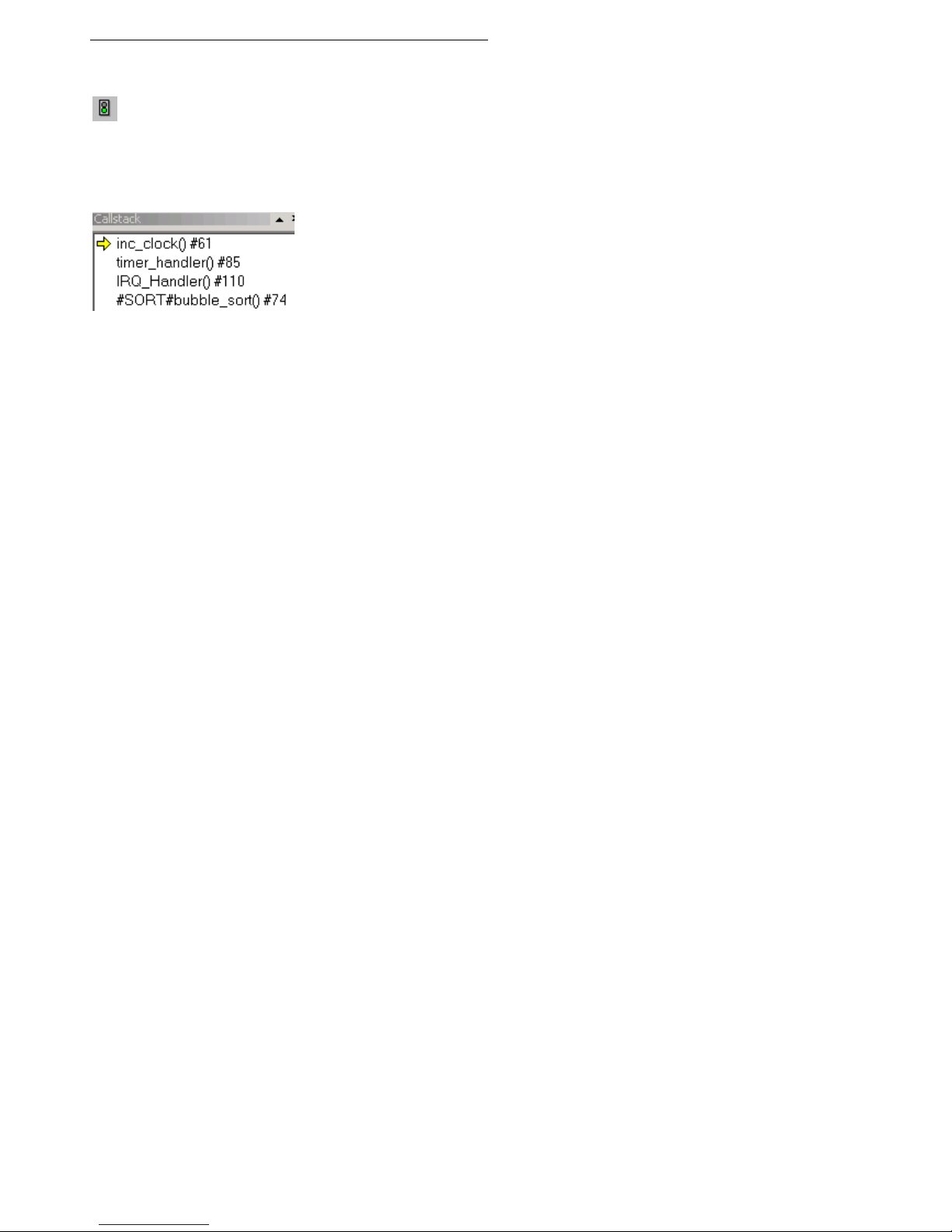
In the Callstack window we see the calling sequence.
The current function 'inc_clock' was called by the 'timer_handler'
which itself was called by the 'IRQ-handler'. The next function listed
is where the interrupt occurred, here it is the function 'bubble_sort',
in your case it is probably another one.

16 Hitex Starter Kit for ARM®/ MCB2100 Board
5 Modifying an Application
To change the code of the application, the Source window's editor
can be used. After saving the files (File menu), the application has
to be rebuilt and reloaded.
If you have installed the GNU compiler included in the installation
CD, you may rebuild the application using the following button in
HiTOP's toolbar:
Results of the build process can be seen in the Output window's
Build tab. Do not forget to download your modified application
again (Debug > Download command).
Details about the GNU compiler can be found in the documentation
included in the compiler's installation files.
6 Trace Debugging (ETM Support)
The Keil MCB2100 board includes the possibility to access the
ARM Embedded Trace Macro Cell (ETM).
Hitex's Tanto for ARM®, the advanced JTAG Development Tool,
can be expanded with an Add-On Module for on-chip ETM support.
Please contact Hitex for more details or visit our WEB site at
http://www.hitex.com/perm/arm_toolchain.html
Table of contents
Other Hitex Motherboard manuals


