hivolt HA2B5-S User manual

1
hivolt.de GmbH & Co. KG
Oehleckerring 40 ∙D-22419 Hamburg ∙Germany ∙+49 40 537122-0 ∙+49 40 537122-99 ∙[email protected] ∙www.hivolt.de
-
HA2B5-S
High Voltage Amplifier ±2000V
HA3B3-S
High Voltage Amplifier ±3000V
HAR42-4
High Voltage Amplifier Mainframe
for 4 Channels HA2B5-S / HA3B3-S
Operating Manual

2
hivolt.de GmbH & Co. KG
Oehleckerring 40 ∙D-22419 Hamburg ∙Germany ∙+49 40 537122-0 ∙+49 40 537122-99 ∙[email protected] ∙www.hivolt.de
1WARNINGS 3
2OVERVIEW 5
3DESCRIPTION 5
3.1 Block Diagram 5
3.2 Control Voltage Input 6
3.3 Monitor Outputs 6
3.4 Differential Output Mode 6
3.5 DISABLE 7
3.6 Loading Conditions 7
3.7 Protection 8
3.8 Interlock / HV Off 8
4TECHNICAL DATA 9
4.1 Frequency Response of Current Monitor 10
4.2 Ambient Conditions 10
4.3 Mechanical Specifications 11
5OPERATION 12
5.1 Initial Check 12
5.2 Warning Notices 12
5.3 Temperature Compensation 12
5.4 Power Supply 13
5.5 Ventilation 13
5.6 Functional Test 13
5.7 Connector X1 INTERLOCK 14
5.8 Output Connector X7 14
5.9 Grounding 14
5.10 DIP Switch S1 14
5.11 Internal Connectors 15
6OPERATION / MAINTENANCE 16
6.1 Troubleshooting 16
6.2 Maintenance 16
6.3 Cleaning 16
7DECLARATION OF CONFORMITY 18

3
hivolt.de GmbH & Co. KG
Oehleckerring 40 ∙D-22419 Hamburg ∙Germany ∙+49 40 537122-0 ∙+49 40 537122-99 ∙[email protected] ∙www.hivolt.de
1Warnings
Caution! This device produces dangerous voltage above 3000V.
Due to capacitive charging, dangerous voltages can still be present in the set-up even after the
amplifier has been switched off!
Please respect the following rules before every activation of the high voltage amplifier:
The device should be operated only by skilled personnel, in accordance with the local regulations
and the instructions given in this manual.
The device may only be operated as a component of an overall structure that fully complies with
the regulations for working with high voltage systems.
Before switching the unit on, the experiment setup must be checked, and safety should be
assured. High voltage areas have to be blocked and secured.
In case of suspected damage or malfunction, the device should immediately be put out of service,
and it should be secured against unintentional or accidental operation.
The safety ground must always be connected! The grounding nut on the rear panel must be
connected to the grounding point of the setup and to protective earth. Local regulations about
grounding should be taken into account.
The output connectors must only be operated when the unit is switched off.
High voltages may still exist even after the switch-off of the device due to capacitive charge!
Capacitances connected to the outputs of the device can possibly remain charged to dangerous
voltages, even after switching off the device
Before removing any covers disconnect the unit from the power supply!
Before touching the output or working on the experimental setup, disconnect the unit from the
power supply!
No wires or similar objects may project into the device through the ventilation slots
Fuses have to be replaced by types as rated on the nameplate on the rear of the unit.
Personal safety must be given the highest priority!

4
hivolt.de GmbH & Co. KG
Oehleckerring 40 ∙D-22419 Hamburg ∙Germany ∙+49 40 537122-0 ∙+49 40 537122-99 ∙[email protected] ∙www.hivolt.de
1 Warnhinweise
Achtung! Dieses Gerät erzeugt lebensgefährliche Spannungen über 3000V.
Vor jeder Inbetriebnahme des Hochspannungsverstärkers sind u. a. folgende Regeln zu beachten:
Die Inbetriebnahme darf nur von einer Elektrofachkraft im Sinne der Berufsgenossenschaft der
Feinmechanik und Elektrotechnik vorgenommen werden.
Vor der Inbetriebnahme muss die Bedienungsanleitung gelesen und verstanden worden sein.
Es sind die einschlägigen Bestimmungen und Vorschriften des Gesetzgebers, der
Berufsgenossenschaft und des VDE zu beachten, insbesondere
-DIN-VDE 104 "Errichten und Betreiben elektrischer Prüfanlagen"
(s. auch BGI 891 "Errichten und Betreiben von elektrischen Prüfanlagen")
-Unfallverhütungsvorschrift DGUV Vorschrift 3 / BGV A3
"Elektrische Anlagen und Betriebsmittel"
Das Gerät darf nur als Bestandteil eines im Ganzen den Vorschriften für den Umgang mit
Hochspannung genügenden Gesamtaufbaus betrieben werden!
Vor jedem Einschalten des Geräts ist der Versuchsaufbau zu überprüfen und sicherzustellen, dass
es zu keiner Gefährdung kommen kann. Die Hochspannung führenden Bereiche müssen
vorschriftengerecht abgesperrt oder anderweitig gesichert sein!
Sollte der Verdacht bestehen, dass das Gerät beschädigt ist oder Fehlfunktionen zeigt, ist es
umgehend außer Betrieb zu setzen und gegen beabsichtigten oder unbeabsichtigten Betrieb zu
sichern.
Der Erdbolzen auf der Rückplatte des Geräts muss mit dem Zentralen Erdpunkt des
Versuchsaufbaus und dem Schutzleiter verbunden werden. Die örtlichen Vorschriften über Erdung
sind zu beachten.
Die Ausgangssteckverbinder dürfen nur bei spannungsfrei geschaltetem Gerät betätigt werden!
Bei Arbeiten am Versuchsaufbau oder bei Berühren der Ausgangsanschlüsse ist das Gerät zuvor
von der Spannungsversorgung zu trennen.
Vor dem Öffnen des Geräts ist das Gerät von der Spannungsversorgung zu trennen.
Es dürfen keine Objekte – wie Drähte o. ä. durch die Lüftungsschlitze in das Gerät Hereinragen.
Im angeschlossenen Versuchsaufbau können evtl. vorhandene Kapazitäten auf Hochspannung
aufgeladen werden. Diese können auch nach Abschalten des Geräts noch gefährliche Spannungen
führen.
Sollte ein Ersatz der Netzsicherungen erforderlich sein, so ist sicherzustellen, dass nur
Sicherungen der angegebenen Nennstromstärke und Nennspannung als Ersatz verwendet
werden.
Der Personensicherheit ist höchste Priorität einzuräumen!

5
hivolt.de GmbH & Co. KG
Oehleckerring 40 ∙D-22419 Hamburg ∙Germany ∙+49 40 537122-0 ∙+49 40 537122-99 ∙[email protected] ∙www.hivolt.de
2Overview
This manual covers the following models:
HA2B5-S single channel high voltage amplifier / 3U plug-in card
HA3B3-S single channel high voltage amplifier / 3U plug-in card
HAR42-4 Tabletop 4U subrack for up to 4 amplifier modules HA2B5-S / HA3B3-S
3Description
The single-channel high voltage amplifiers HA2B5-S / HA3B3-S with bipolar output voltage are
designed to drive capacitive and resistive-capacitive loads.
The amplifiers are characterized by high speed, good stability and low noise. Piezo elements,
electroactive polymers, electrorheological fluids, electrostatic deflecting electrodes and many other
loads can be driven by this amplifier easily.
For HA2B5-S output voltages of -2000V to +2000V at load currents of up to ±5mA and >7mAPare
provided. The signal gain is 200, the input voltage range is -10V…+10V.
For HA3B3-S output voltages of -3000V to +3000V at load currents of up to ±3mA and >5mAPare
provided. The signal gain is 300, the input voltage range is -10V…+10V.
The output voltage can be monitored by a high-speed voltage monitor; a current monitor provides a
representation of the output current.
HA2B5-S and HA3B3-S are 3U plug-in cards intended to be mounted in a suitable subrack.
The deviced incorporate the high voltage amplifier itself, high voltage sources for the output stage,
measuring functions as well as monitoring and protective functions.
The amplifier’s output is protected against overload, short circuit, overtemperature, transient
overvoltage and high voltage flashover. LEDs on the front panel indicate operation and error statuses.
The HAR42-4 is a tabletop subrack to accommodate up to 4 high voltage amplifier modules HA2B5-S
or HA3B3-S. Both models can be combined in a single subrack.
It features internal power supplies, cooling fans, a common Interlock input for all channels and a HV
OFF button. Customized and full custom models are available on request.
3.1 Block Diagram

6
hivolt.de GmbH & Co. KG
Oehleckerring 40 ∙D-22419 Hamburg ∙Germany ∙+49 40 537122-0 ∙+49 40 537122-99 ∙[email protected] ∙www.hivolt.de
3.2 Control Voltage Input
The BNC control voltage input In is connected to a differential amplifier to suppress common mode
voltages between the external signal source and the amplifier (ground loops). Two jumpers (W2, W5)
are provided on each amplifier module in order to adapt the control voltage input to the signal source.
W5 connects the input signal reference via 100Ωto the amplifier signal ground. W2 adjusts the
amplifier gain to the output impedance of the signal source.
W5
1-2 Floating signal source
Common mode voltage <1VRMS
Default
2-3 Grounded signal source (connected to PE)
Common mode voltage <5VRMS
W2
1-2 Output impedance of signal source <1 ΩDefault
2-3 Output impedance of signal source 50 Ω
3.3 Monitor Outputs
Two BNC monitor outputs provide actual values of output voltage and output
current, both of which are normalized to ±10 V.
The voltage monitor output V Mon receives its signal via a compensated voltage
divider and provides a scaled image of the output voltages. The frequency
response is linear up to well above the upper cut-off frequency of the
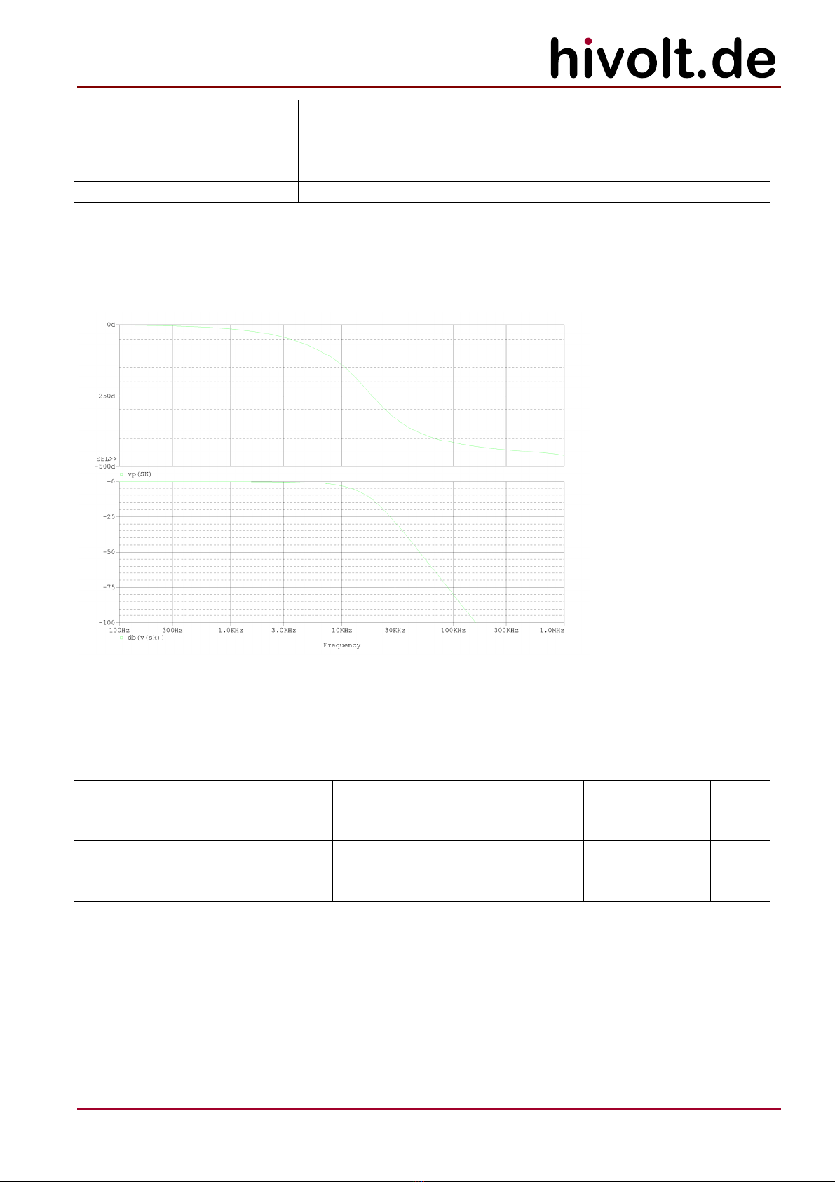
amplifiers. The frequency response of the I Mon current monitor output is
limited to about 9kHz in order to filter out the common mode ripple of the
internal high voltage sources.
The monitor outputs are buffered (output impedance: 2kΩ) and short-circuit-proof. They are able to
drive capacitive loads (coaxial cables), but are not designed to drive cables with a low-impedance
termination.
3.4 Differential Output Mode
Two amplifier modules can be configured to operate in a differential output mode. In this
configuration, only amplifier 1 (Master) receives the input signal from the signal source. Amplifier 2
(Slave) receives the input signal through the backplane of the subrack. The signal to amplifier 2 is
inverted (180° phase shift in respect to amplifier 1).
This mode can be used e. g. to differentially drive two deflection plates or to drive a floating load with
up to 8000VPP.

7
hivolt.de GmbH & Co. KG
Oehleckerring 40 ∙D-22419 Hamburg ∙Germany ∙+49 40 537122-0 ∙+49 40 537122-99 ∙[email protected] ∙www.hivolt.de
Two jumpers (W3, W4) are provided on each amplifier module to configure differential output mode:
W3
1-2 Master Default
2-3 Slave
W4
1-2 Master Default
2-3 Slave
3.5 DISABLE
The high voltage amplifier channels can be remotely switched off through the DISABLE input. The
signal is available through connector X1 INTERLOCK on the HAR42-4 rear panel. It is TTL-compatible.
A LOW-signal turns on all amplifier outputs. In case of open input or HIGH signal, the amplifier
outputs are forced to 0V. During disable the internal high voltage sources are not turned off. The
DISABLE input can be used to turn on and off the amplifier outputs relatively fast.
If the DISABLE input is not needed, a wire jumper can be installed between DISABLE (X1.4) and GND
(X1.5) to turn on the amplifiers permanently.
The DISABLE input is not suitable to achieve a safe state at the amplifier output. It must not be used
for safety relevant purposes.
3.6 Loading Conditions
The amplifiers are designed to drive capacitive and resistive-capacitive loads. The output is stable
even with large capacitive loads. In case of larger load capacitances overshoot of the output may
occur.
The slew rate that can be achieved on the output depends on the load capacitance. The effective load
capacitance CLconsists of the amplifier’s internal output capacitance (ca. 80pF), capacitance of the
output cable (a typical coaxial cable: ca. 100pF/m) and capacitance of the connected load.
The output stage can provide peak currents (IOP) of > ±7.5mAPfor ca. 1s. The maximum static output
current is +5mA and -5mA.
Achievable slew rate: SR = IO/ CL[V/s].
If the average positive or negative output current exceeds 5mA (HA2B5-S) or 3mA (HA3B3-S) the
amplifier shuts down with Overload.
If the maximum slew rate is exceeded, distortions occur in the output signals. In principle, the
amplifier should thus only be controlled by input signals that satisfy the achievable slew rate for a
given load. However, dynamic override of the inputs (e.g. control by square wave signals) is harmless.
The edges of the output waveform are nearly linear then with a slight overshoot.
Large capacitive loads driven by high frequency signals may result in a DC-offset superimposed on the
output voltage. This occurs if the final value of the desired output voltage can not be reached
periodically.

8
hivolt.de GmbH & Co. KG
Oehleckerring 40 ∙D-22419 Hamburg ∙Germany ∙+49 40 537122-0 ∙+49 40 537122-99 ∙[email protected] ∙www.hivolt.de
3.7 Protection
During operation, the internal auxiliary supplies, overload of the high voltage sources, overtempera-
ture and interlock are monitored. In the event of a fault, the high voltage supplies are switched off; the
shutdown state is latched and displayed on LEDs.
A shutdown state can only be exited by means of a shutdown reset (push button SDN Reset on the
HAR42-4 front panel or signal SDR (X1.1) on connector X1 INTERLOCK set to +24V).
After power on the unit will be in shutdown state.
LED Function
Enable on: output stage is enabled by signal DISABLE=low
HV ok on: internal HV sources on, no overload
Interlock on: shutdown: interlock circuit open
blink: shutdown after interlock
Overload on: overload
blink: shutdown due to overload
Overtemp on: overtemperature
blink: shutdown due to overtemperature
3.8 Interlock / HV Off
The amplifier modules incorporate an interlock circuit through which the supply voltage of the high
voltage sources is switched.
The interlock signal is available via the rear connector X1 INTERLOCK on the subrack. The HV off
palm button is looped into the interlock circuit. It is a closed circuit (break contacts). Its source voltage
is 24VDC.
To enable the high voltage generators +24V_IL (X1.2) and IL (X1.3) must be connected by a jumper or
a contact. The contact can be part of an external interlock circuit. The quiescent current is 30mA typ.
When the interlock circuit is closed and the HV off palm button is released, the palm button will be lit
to indicate that the high voltage sources are switched on.
The high voltage generation is not in operation until the Interlock shutdown state is cleared by
shutdown reset.
The device must be disconnected
from the power supply before
carrying out any operations on the
test setup or before touching the
output terminals.

9
hivolt.de GmbH & Co. KG
Oehleckerring 40 ∙D-22419 Hamburg ∙Germany ∙+49 40 537122-0 ∙+49 40 537122-99 ∙[email protected] ∙www.hivolt.de
4Technical Data
Mainframe HAR42-4
Parameter Conditions
Mains voltage 95 – 265VAC
Mains frequency 47 – 63Hz
Input current VLine=115VAC, full load 1.0ARMS maximum
VLine=230VAC, full load 0.5ARMS maximum
Mains Fuses F1, F2 T6.3A, 250V, IEC127-2/V
External Fusing 16A
Protection Category I
-Fuses F1, F2 are located within the mains connector unit on the rear.
-Signal ground and high voltage ground are connected to chassis ground / protective earth and the
earth connector (M4 nut).
-The appliance conforms to protection category I. It must only be used on mains power sockets with
a ground connection.
Amplifier modules HA2B5-S / HA3B3-S
Parameter Conditions
Supply voltage, VS24VDC ±10%
Supply current, ISVS= 24V <1.6ADC
Input voltage range Control input -10.0V – +10.0V
Max. input voltage ±18V
Input resistance 25kΩtyp.
DC Gain HA2B5-S
HA3B3-S
200 ±0.1%
300 ±0.1%
Offset ≤100mV
Output voltage range HA2B5-S
HA3B3-S
-2000V – +2000V
-3000V – +3000V
Load current range static HA2B5-S
HA3B3-S
-5mA – +5mA
-3mA – +3mA
Load current range dynamic, t < 1ms HA2B5-S
HA3B3-S
-7mA – +7mA
-5mA – +5mA
Power bandwidth CL= 0pF, THD ≤1%
VO = 4000VPP HA2B5-S
VO = 6000VPP HA3B3-S
DC – ≥5kHz
DC – ≥2.5kHz
Power bandwidth CL= 100pF, THD ≤1%
VO = 4000VPP HA2B5-S
VO = 6000VPP HA3B3-S
DC – ≥2.5kHz
DC – ≥1.3kHz
Small Signal Bandwidth CL= 100pF, VI= 2VPP, VO-3dB DC – ≥20kHz
Slew-Rate CL= 100pF HA2B5-S
HA3B3-S
≥40V/μs
≥25V/μs
Internal output capacitance ca. 80pF
Ripple, Noise CL= 100pF, HA2B5-S
1Hz – 20kHz HA3B3-S
≤20mVRMS
≤20mVRMS
10
hivolt.de GmbH & Co. KG
Oehleckerring 40 ∙D-22419 Hamburg ∙Germany ∙+49 40 537122-0 ∙+49 40 537122-99 ∙[email protected] ∙www.hivolt.de
Scaling monitor output V HA2B5-S
HA3B3-S
10V 2000V ±0.2%
10V 3000V ±0.2%
Bandwidth monitor output V DC – ≥50kHz
Scaling monitor output I 10V 10mA ±1%
Bandwidth monitor output I DC – ≥9kHz
-Signal ground and high voltage ground are connected to the chassis ground / earth terminal.
4.1 Frequency Response of Current Monitor
4.2 Ambient Conditions
Parameter Conditions Min. Max. Unit
Ambient temperature
- Operation
- Storage and Transportation
-20
-25
+50
+70
°C
°C
Relative humidity
- Operation
- Storage and Transportation
Not condensing
5
5
80
95
%
%
-Depending on the ambient temperature, modulation amplitude and load capacitance, the maximum
output power may need to be derated.

11
hivolt.de GmbH & Co. KG
Oehleckerring 40 ∙D-22419 Hamburg ∙Germany ∙+49 40 537122-0 ∙+49 40 537122-99 ∙[email protected] ∙www.hivolt.de
4.3 Mechanical Specifications
Mainframe HAR42-4
Parameter Unit
Depth overall 490 mm
Depth case 420 mm
Width overall 250 mm
Width case 235 mm
Height 185 mm
Weight without amplifier modules 4.0 kg
Amplifier module HA2B5-S / HA3B3-S
Parameter Unit
Depth overall 255 mm
Depth module 235 mm
Width 40 mm
Height 128 mm
Weight 0.51 kg

12
hivolt.de GmbH & Co. KG
Oehleckerring 40 ∙D-22419 Hamburg ∙Germany ∙+49 40 537122-0 ∙+49 40 537122-99 ∙[email protected] ∙www.hivolt.de
5Operation
5.1 Initial Check
Once the product is delivered, please check the packaging and the device for possible transport
damage. Please check the device taken out of the packaging for any mechanical defects before the
unit is put into operation.
If the device has any signs of damage caused by transport, please immediately inform the shipping
company so that damages can be claimed.
5.2 Warning Notices
-For safe operation of this device it should be put into operation by a qualified electrician according
to this Operating Manual.
-The device may only be operated as a component of an overall setup that fully complies with the
regulations for working with high voltage systems.
-Output connectors may only be touched when the device is disconnected from the power supply!
Otherwise, there is a risk of electric shock.
-The test setup must be fully wired and protected against any contact before the device is put into
operation.
-The test setup must be checked each time before the device is put into operation to ensure that it
is not potentially dangerous. It should be checked that the high voltage connections are faultless
and the insulation of the wires is not damaged.
-The high-voltage areas must be blocked in accordance with regulations or secured by other
means.
-Once the test setup is connected, any existing capacitances can be charged to high voltage. They
may carry dangerous voltages even after the device is switched off.
-The ground bolt on the rear panel of the device must be connected to the central grounding point
of the test setup and to protective earth. Local regulations on grounding must be observed.
-No wires or similar objects may project into the device through the ventilation slots
-If it is suspected that safe operation is no longer possible, the device has to be taken out of
operation and secured against unintentional operation.
This symbol on the output terminals warns of the risk of electric shock.
5.3 Temperature Compensation
To avoid condensation within the device, it should be allowed to reach the room temperature. Please
unpack the product at least two hours prior to power-up.

13
hivolt.de GmbH & Co. KG
Oehleckerring 40 ∙D-22419 Hamburg ∙Germany ∙+49 40 537122-0 ∙+49 40 537122-99 ∙[email protected] ∙www.hivolt.de
5.4 Power Supply
The HAR42-4 subrack provides the 24V supply voltage for the amplifier modules.
The mainframe is fed by mains voltage.
5.5 Ventilation
The HAR42-4 subrack is equipped with fans on the rear panel. Air intake is below the front panels.
Sufficient space must be allowed for cooling air to reach the ventilation inputs and for the fan exhaust
air to exit from the rear of the unit.
The speed of the fans is controlled automatically by the temperature of the amplifier modules.
5.6 Functional Test
Before the device is finally put into operation in a setup, a short functional test is to be carried out.
It is necessary that the interlock circuit is closed.
1. Make sure that the supply voltage is disconnected.
2. Remove all input signal cables and the output cable from the device.
3. Connect the terminals +24V_IL (X1.2) and IL (X1.3) by means of a wire link.
4. Connect the terminals DISABLE (X1.4) and GND (X1.5) by means of a wire link.
5. Connect the mains supply voltage.
6. Switch on the Power switch.
7. Release the HV off palm button.
8. The Power switch and HV off button will light up, Enable LEDs will light up,
IL, Overload and Overtemp LEDs will flash.
9. Push the SDN Reset push button.
10. The IL, Overload and Overtemp LEDs will turn off, the HV ok LEDs will light up.
11. Push in the HV off palm button.
12. The HV off button and HV ok LEDs will turn off, the IL LEDs will light up.
13. Open the interlock bridge at X1.
14. Release the HV off palm button.
15. The Interlock LEDs will light up continuously.
16. Press the SDN Reset push button.
17. The interlock status remains unchanged and the high voltage cannot be switched on.
18. Turn off the supply voltage.

14
hivolt.de GmbH & Co. KG
Oehleckerring 40 ∙D-22419 Hamburg ∙Germany ∙+49 40 537122-0 ∙+49 40 537122-99 ∙[email protected] ∙www.hivolt.de
5.7 Connector X1 INTERLOCK
Connector type: Phoenix Mini-Combicon, 5-pin
Mating connector: Phoenix Mini-Combicon, 5 circuits, FK-MCP1.5_ 5-ST-3.81
Pin Signal Direction Function
1 SDR I Control signal: 24V for 0.2s => Shutdown Reset;
Caution: This reactivates the HV output after a shutdown!
2 +24V_IL O 24V output for interlock circuit and SDR signal;
protected against overload
3 IL I Interlock / bridge to X1.+24V_IL
4 DISABLE I Control signal: TTL compatible; 2.5kΩinternal pull-up resistor;
LOW == enable amplifier outputs
5 GND - Supply voltage GND
5.8 Output Connector X7
Connector type: SHV
The high voltage connector may only be mated or unmated when the supply voltage is switched off!
Otherwise, there is a risk of an electric shock.
5.9 Grounding
The M4 ground nut on the back panel of the device must be connected to the central grounding point
of the test setup and to protective earth.
5.10 DIP Switch S1
Switch Function Default
S1-1 Disable Interlock shutdown latch OFF
S1-2 Disable Overload shutdown latch OFF
S1-3 Disable Overtemperature shutdown latch OFF
S1-4 not used
For safety reasons it is not recommended to disable the shutdown latches. In case of disabled
shutdown latches high voltage will reappear at the outputs after a shutdown condition (Interlock,
Overload, Overtemperature) is no longer pending.
It is recommended to operate the unit with shutdown latches enabled and actively reset any shutdown
condition via the SDN Reset push button or the SDN signal on X1.
15
hivolt.de GmbH & Co. KG
Oehleckerring 40 ∙D-22419 Hamburg ∙Germany ∙+49 40 537122-0 ∙+49 40 537122-99 ∙[email protected] ∙www.hivolt.de
5.11 Internal Connectors
Internal connector X1 of HA2B5-S / HA3B3-S plug-in modules (DIN41612, Type F)
Pins Signal Dir Function
D2 B2 Z2 n.c.
D4 B4 Z4 n.c.
D6 B6 Z6 n.c.
D8 B8 Z8 n.c.
D10 B10 Z10 n.c.
D12 B12 Z12 GND - GND
D14 B14 Z14 n.c.
D16 B16 Z16 n.c.
D18 HVON_BP I HV enable input; used for interlock or general high voltage
ON; approx. 10mA @ 24V
B18 SDNRST_BP I Shutdown reset input; clear latched shutdown conditions;
tP>200ms @ 24V; approx. 2.5mA @ 24V
Z18 DISABLE_BP I Disable input; TTL compatible; 10kΩinternal pull-up resistor
to +5V; LOW == enable amplifier outputs; tD≈50ms; see 3.5
D20 STAT_BP O Status output; 5V; HIGH == high voltage generation enabled
B20 VFCON O Fan control output; 100mV/°C; 9.3V == 100°C;
min. load: 10kΩ; DO NOT OVERLOAD OR SHORT TO GND
Z20 CHA_SEL_BP I Channel select input; TTL compatible; 10kΩinput resistance;
HIGH == activate backpanel monitor outputs IOAV_BP and
VOAV_BP
D22 VOAV_BP O Output voltage monitor output; ±10V; must be activated via
CHA_SEL_BP; high impedance if disabled; see 3.3
B22 IOAV_BP O Output current monitor output; ±10V; must be activated via
CHA_SEL_BP; high impedance if disabled; see 3.3
Z22 AV_RTN - Monitor output reference point; connected to analog GND
D24 INP_S I Slave unit pos. differential input; ±10V; see 3.4
B24 INP_S I connected to D24
Z24 INN_S I Slave unit neg. differential input; ±10V; see 3.4
D26 VONV_BP O Inverted input signal output; ±10V; used to drive 2nd channel
module in differential mode; see 3.4
B26 VONV_BP O connected to D26
Z26 INN_S I connected to Z24
D28 VONV_RTN - VONV_BP output reference point; connected to analog GND
B28 VONV_RTN - connected to D28
Z28 VT_MAX O Temperature monitor output; 100mV/°C; 10V == 100°C;
min. load: 10kΩ; DO NOT OVERLOAD OR SHORT TO GND
D30 B30 Z30 +24V I +24VDC supply voltage input
D32 B32 Z32 GND - GND

16
hivolt.de GmbH & Co. KG
Oehleckerring 40 ∙D-22419 Hamburg ∙Germany ∙+49 40 537122-0 ∙+49 40 537122-99 ∙[email protected] ∙www.hivolt.de
6Operation / Maintenance
6.1 Troubleshooting
If the device behaves unusual or erratic, please switch off the supply voltage and check the wiring of
the load and that of the control and monitoring signals. Check the connected load and the signal
source. Check the interlock circuit.
During operation various parameters are monitored and analyzed. In case of a fault the error is
reported via error LEDs on the front panel of the amplifier module. Press the SDN Reset push button
to reset the error condition.
Do not attempt to locate any faults within the device. This can be dangerous to life due to the high
voltage used in the device. In such a case, please return the device to the manufacturer after
consultation.
Symptom Possible causes
Device will not turn on; Power LED
will not light up
-No supply voltage present
-Fuses F1, F2 in the IEC inlet defective
HV off palm button will not light up -HV off palm button is in off position (pushed in)
-Interlock circuit is open
Output signal is distorted -Load capacitance too large for the desired slew rate
(see section 3.6 for load conditions)
Amplifier switches off, the
OVERLOAD indicator lights up
-Dynamic load current exceeded (see section 3.6 for load
conditions)
-Static load current exceeded (see section 3.6 for load
conditions)
Amplifier switches off, the
OVERTEMP indicator lights up
-Poor ventilation
-Total load too large (see section 3.6 for load conditions)
6.2 Maintenance
Depending on the cleanliness of the ambient air dust may accumulate within the unit possibly blocking
the airflow. In that case the accumulated dust has to be removed by blowing out the unit cautiously.
The manufacturer specified lifetime of the fans is >50000h. After about 6 years of continuous operation
the fans might be replaced.
Type: Papst 8314H (HAR42-4).
Caution: disconnect the unit from the power supply before removing any modules or opening any
covers.
Further regular maintenance is not required.
6.3 Cleaning
If necessary, wipe the device with a slightly damp cloth. Do not use abrasive detergents or solvents.

17
hivolt.de GmbH & Co. KG
Oehleckerring 40 ∙D-22419 Hamburg ∙Germany ∙+49 40 537122-0 ∙+49 40 537122-99 ∙[email protected] ∙www.hivolt.de
© hivolt.de GmbH&Co. KG, Hamburg, Germany
As of 03/2021
Document History:
Version Date Name Changes
1.0 2019-09-03 WM Created
1.1 2020-10-19 WM extended description of internal connector X1
1.2 2021-03-09 WM HA3B3-S added
1.3 2021-07-16 WM pin-assignment X1 IOAV_BP, VOAV_BP corrected

18
hivolt.de GmbH & Co. KG
Oehleckerring 40 ∙D-22419 Hamburg ∙Germany ∙+49 40 537122-0 ∙+49 40 537122-99 ∙[email protected] ∙www.hivolt.de
7Declaration of Conformity
We declare under sole responsibility that the products
Device: High Voltage Amplifiers
Series: HA2B5-S, HA3B3-S
Subrack HAR42-4
are in accordance with the following European directives:
Low Voltage Directive 2014/35/EU
EMC Directive 2014/30/EU
and comply with the following European standards:
EN 61010-1:2010 Safety requirements for electrical equipment for
measurement, control, and laboratory use -
Part 1: General requirements
EN 61326-1:2013 Electrical equipment for measurement, control and
laboratory use -
EMC requirements - Part 1: General requirements
Classification: Group 1, Class B
Manufacturer:
hivolt.de GmbH & Co. KG
Oehleckerring 40
D-22419 Hamburg
2021-03-09
Wulf Müller
Managing Director
This manual suits for next models
2
Table of contents
Other hivolt Amplifier manuals


