hivolt HAR12S User manual
1
hivolt.de GmbH & Co. KG
Oehleckerring 40 ∙D-22419 Hamburg ∙Germany ∙+49 40 537122-0 ∙+49 40 537122-99 ∙[email protected] ∙www.hivolt.de
HAR12S
12 Channel High Voltage Amplifier Mainframe
HAR2
2 Channel High Voltage Amplifier Mainframe
HA05B2
High Voltage Amplifier ±500V
Operating Manual

2
hivolt.de GmbH & Co. KG
Oehleckerring 40 ∙D-22419 Hamburg ∙Germany ∙+49 40 537122-0 ∙+49 40 537122-99 ∙[email protected] ∙www.hivolt.de
1WARNINGS 3
2OVERVIEW 5
3DESCRIPTION 5
3.1 Block Diagram 6
3.2 Control Voltage Input 7
3.3 Monitor Outputs 7
3.4 INHIBIT 8
3.5 Loading Conditions 8
3.6 Interlock 9
3.7 Connector INTERLOCK 9
4TECHNICAL DATA 10
4.1 Ambient Conditions 11
4.2 Mechanical Specifications 12
5OPERATION 13
5.1 Initial Check 13
5.2 Warning Notices 13
5.3 Temperature Compensation 13
5.4 Power Supply 14
5.5 Ventilation 14
5.6 Wall Mounting HAR2-W 14
5.7 Rack Mounting HAR12 15
5.8 Functional Test 15
5.9 Output connections 15
5.10 Output Connectors 15
5.11 External Connectors 16
5.12 Internal Connectors 16
5.13 Grounding 16
5.14 Troubleshooting 17
5.15 Maintenance 17
5.16 Cleaning 17
6DECLARATION OF CONFORMITY 18

3
hivolt.de GmbH & Co. KG
Oehleckerring 40 ∙D-22419 Hamburg ∙Germany ∙+49 40 537122-0 ∙+49 40 537122-99 ∙[email protected] ∙www.hivolt.de
1Warnings
Caution! This device produces dangerous voltage above 500V.
Due to capacitive charging, dangerous voltages can still be present in the set-up even after the
amplifier has been switched off!
Please respect the following rules before every activation of the high voltage amplifier:
The device should be operated only by skilled personnel, in accordance with the local regulations
and the instructions given in this manual.
The device may only be operated as a component of an overall structure that fully complies with
the regulations for working with high voltage systems.
Before switching the unit on, the experiment setup must be checked, and safety should be
assured. High voltage areas have to be blocked and secured.
In case of suspected damage or malfunction, the device should immediately be put out of service,
and it should be secured against unintentional or accidental operation.
The safety ground must always be connected! The grounding nut on the rear panel must be
connected to the grounding point of the setup and to protective earth. Local regulations about
grounding should be taken into account.
The output connectors must only be operated when the unit is switched off.
High voltages may still exist even after the switch-off of the device due to capacitive charge!
Capacitances connected to the outputs of the device can possibly remain charged to dangerous
voltages, even after switching off the device
Before removing any covers disconnect the unit from the power supply!
Before touching the output or working on the experimental setup, disconnect the unit from the
power supply!
No wires or similar objects may project into the device through the ventilation slots
Fuses have to be replaced by types as rated on the nameplate on the rear of the unit.
Personal safety must be given the highest priority!

4
hivolt.de GmbH & Co. KG
Oehleckerring 40 ∙D-22419 Hamburg ∙Germany ∙+49 40 537122-0 ∙+49 40 537122-99 ∙[email protected] ∙www.hivolt.de
1 Warnhinweise
Achtung! Dieses Gerät erzeugt gefährliche Spannungen über 500V.
Vor jeder Inbetriebnahme des Hochspannungsverstärkers sind u. a. folgende Regeln zu beachten:
Die Inbetriebnahme darf nur von einer Elektrofachkraft im Sinne der Berufsgenossenschaft der
Feinmechanik und Elektrotechnik vorgenommen werden.
Vor der Inbetriebnahme muss die Bedienungsanleitung gelesen und verstanden worden sein.
Es sind die einschlägigen Bestimmungen und Vorschriften des Gesetzgebers, der
Berufsgenossenschaft und des VDE zu beachten, insbesondere
-DIN-VDE 104 "Errichten und Betreiben elektrischer Prüfanlagen"
(s. auch BGI 891 "Errichten und Betreiben von elektrischen Prüfanlagen")
-Unfallverhütungsvorschrift DGUV Vorschrift 3 / BGV A3
"Elektrische Anlagen und Betriebsmittel"
Das Gerät darf nur als Bestandteil eines im Ganzen den Vorschriften für den Umgang mit
Hochspannung genügenden Gesamtaufbaus betrieben werden!
Vor jedem Einschalten des Geräts ist der Versuchsaufbau zu überprüfen und sicherzustellen, dass
es zu keiner Gefährdung kommen kann. Die Hochspannung führenden Bereiche müssen
vorschriftengerecht abgesperrt oder anderweitig gesichert sein!
Sollte der Verdacht bestehen, dass das Gerät beschädigt ist oder Fehlfunktionen zeigt, ist es
umgehend außer Betrieb zu setzen und gegen beabsichtigten oder unbeabsichtigten Betrieb zu
sichern.
Der Erdbolzen auf der Rückplatte des Geräts muss mit dem Zentralen Erdpunkt des
Versuchsaufbaus und dem Schutzleiter verbunden werden. Die örtlichen Vorschriften über Erdung
sind zu beachten.
Die Ausgangssteckverbinder dürfen nur bei spannungsfrei geschaltetem Gerät betätigt werden!
Bei Arbeiten am Versuchsaufbau oder bei Berühren der Ausgangsanschlüsse ist das Gerät zuvor
von der Spannungsversorgung zu trennen.
Vor dem Öffnen des Geräts ist das Gerät von der Spannungsversorgung zu trennen.
Es dürfen keine Objekte – wie Drähte o. ä. durch die Lüftungsschlitze in das Gerät Hereinragen.
Im angeschlossenen Versuchsaufbau können evtl. vorhandene Kapazitäten auf Hochspannung
aufgeladen werden. Diese können auch nach Abschalten des Geräts noch gefährliche Spannungen
führen.
Sollte ein Ersatz der Netzsicherungen erforderlich sein, so ist sicherzustellen, dass nur
Sicherungen der angegebenen Nennstromstärke und Nennspannung als Ersatz verwendet
werden.
Der Personensicherheit ist höchste Priorität einzuräumen!

5
hivolt.de GmbH & Co. KG
Oehleckerring 40 ∙D-22419 Hamburg ∙Germany ∙+49 40 537122-0 ∙+49 40 537122-99 ∙[email protected] ∙www.hivolt.de
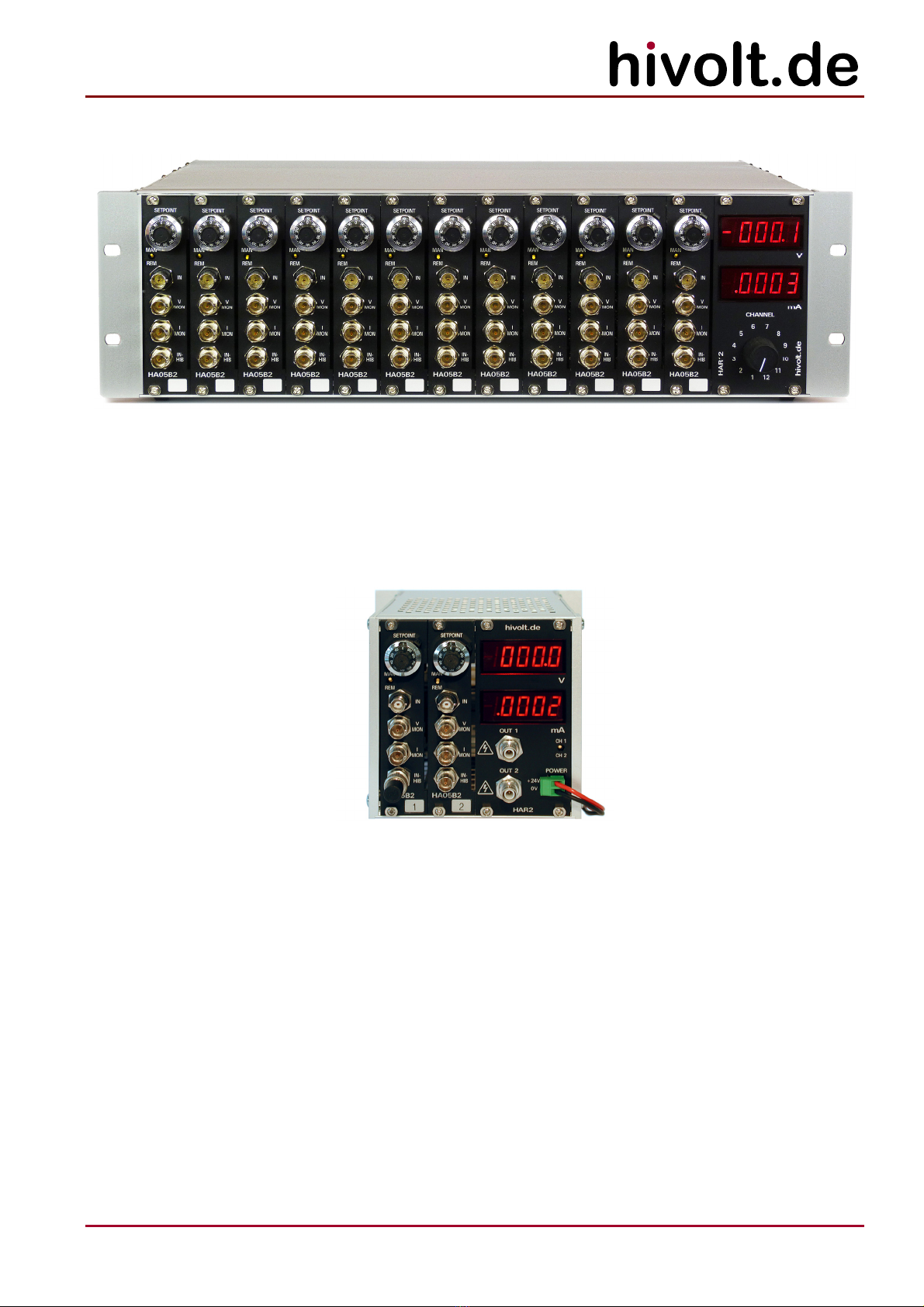
2Overview
This manual covers the following models:
HA05B2 single channel high voltage amplifier module family
HAR12S 12-channel high voltage amplifier mainframe (SHV output connectors)
HAR2 2-channel high voltage amplifier mainframe (SHV output connectors)
table top unit
HAR2-W 2-channel high voltage amplifier mainframe (SHV output connectors)
wall mount unit
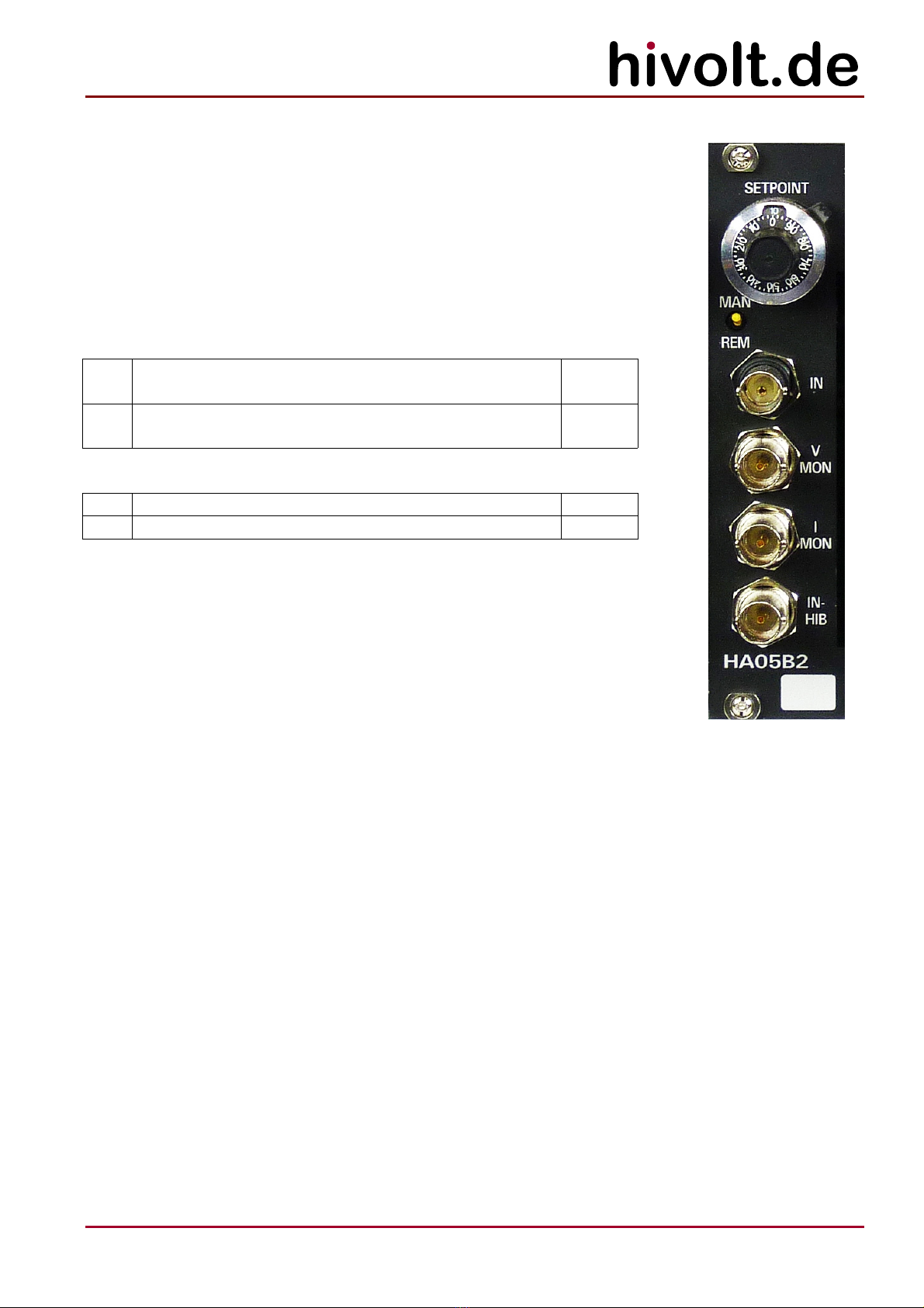
3Description
The high voltage amplifier channel module HA05B2 with bipolar output voltage is designed to drive
capacitive and resistive-capacitive loads.
The amplifier channels are characterized by high accuracy, very high stability and very low noise.
High precision electrostatic deflection or multi channel high voltage reference source are typical
applications.
A version with extended bandwidth is available: HA05B2_BA.
Output voltages of -500V to +500V at load currents of up to ±2mA are provided. The signal gain is 50,
the input voltage range is -10V…+10V.
The output voltages of each channel can be controlled by a control voltage (IN) or by a 10-turn
potentiometer (SETPOINT). Each channel is equipped with a precision high-speed voltage monitor
output, current monitor output and an inhibit input.
The amplifier outputs are protected against overload, short circuit, and transient overvoltage.
The HA05B2 is a 3U plug-in card intended to be mounted in a suitable subrack.
The HAR2/HAR2-W mainframes accommodate up to 2 amplifier channel modules HA05B2.
HAR2 is a table top unit, HAR2-W is a wall-mount type.
The 19"/3U HAR12 mainframe accommodates up to 12 amplifier channel modules HA05B2.
It features internal power supplies, cooling fans and a common Interlock input for all channels.
All mainframes contain two DVMs and the high voltage converters to feed the HA05B2 amplifier
channel modules.
Both the output voltage and the load current of each channel can be displayed on the DVMs.
A switch (CHANNEL) is provided for selection of the channel to be measured.
The HAR12 is supplied by mains voltage. The HAR2 models are supplied by an external 24VDC.
Customized and full custom models are available on request.

6
hivolt.de GmbH & Co. KG
Oehleckerring 40 ∙D-22419 Hamburg ∙Germany ∙+49 40 537122-0 ∙+49 40 537122-99 ∙[email protected] ∙www.hivolt.de
3.1 Block Diagram
1N
IN
-
10K0
A3
SETPOINT
I NHI B
+540V
A2
I-MON
A3
W2
1
2
3
X5
Spannungsregler V1 9
1K00
-10.0V
MAN
V24
VO
I NHI B
A4
V-MON
49R9
INHIB
-540V
X6
X7
CMR
X4
CW
CC W
+
REM
+10.0V
10R0 OFFSET
W1
1
2
3
The block diagram shows one amplifier channel.
7
hivolt.de GmbH & Co. KG
Oehleckerring 40 ∙D-22419 Hamburg ∙Germany ∙+49 40 537122-0 ∙+49 40 537122-99 ∙[email protected] ∙www.hivolt.de
3.2 Control Voltage Input
The control voltage input (IN) is connected to a differential amplifier to
suppress common mode voltages between the external signal source and
the amplifier. Two jumpers (W1, W2) are provided on each amplifier module
HA05B2 in order to adapt the control voltage input to the signal source.
W1 connects the input signal reference via 10Ωto the amplifier signal
ground. W2 adjusts the amplifier gain to the output impedance of the signal
source.
W1
1-2 Floating signal source
Common mode voltage <1VRMS
Default
2-3 Grounded signal source (connected to PE)
Common mode voltage <5VRMS
W2
1-2 Output impedance of signal source <1ΩDefault
2-3 Output impedance of signal source 50Ω
Alternatively, the control voltage can be generated by means of a 10-turn
potentiometer (SETPOINT). The potentiometer supplies –10 V at the CCW
end position (0) and +10 V at the CW end position (10). Zero position is at 5.
Switching between internal and external control voltage is achieved by a
front panel switch (MAN / REM).
3.3 Monitor Outputs
Two BNC monitor outputs (V-MON / I-MON) provide actual values of output voltage and output current,
both of which are normalized to ±10 V.
The monitor outputs receive their signal through a compensated voltage divider. Current
measurement takes place differentially across a sense resistor in the output line. Due to differential
measurement, a certain drift of the measured output current over temperature and output voltage is
inevitable (refer to technical specifications).
The frequency response of V-MON is linear up to well above the upper cut-off frequency of the
amplifiers.
The monitor outputs are buffered and short-circuit-proof. They are able to drive capacitive loads
(coaxial cables), but are not designed to drive cables with a low-impedance termination.

8
hivolt.de GmbH & Co. KG
Oehleckerring 40 ∙D-22419 Hamburg ∙Germany ∙+49 40 537122-0 ∙+49 40 537122-99 ∙[email protected] ∙www.hivolt.de
3.4 INHIBIT
Each high voltage amplifier channel can be remotely switched off through the INHIB input. The input is
TTL-compatible. A LOW-signal turns on the amplifier. In case of open input or HIGH-signal, the
amplifier is turned off. For manual operation, a 50ΩBNC-termination resistor can be used to statically
turn the amplifier channel on.
The Inhibit signal drives a semiconductor switch, short-circuiting the output (approx. 100Ω) within
microseconds. The switch conducts independently of the internal supply voltage, even after the device
is switched-off.
The INHIB input is not suitable to achieve a safe state at the amplifier output. It must not be used for
safety relevant purposes.
3.5 Loading Conditions
The amplifiers are designed to drive any combination of resistive and capacitive loads.
Full output voltage is available for resistive loads ≥250kΩ. When driving capacitive loads the reactive
current must be taken into consideration. This current into the load capacitance depends on the
capacitance value and the slew-rate: iCL = CL* dv / dt.
The effective load capacitance consists of the connected load capacitance, the capacitance of the
output cable, and the capacitance internal to the amplifier. If the output current exceeds the peak
current capability of the amplifier module (refer to the specifications), the output voltage will become
distorted.
In case of larger load capacitances overshoot of the output may occur.
The achievable large-signal bandwidth strongly depends on the capacitance of the connected load.
Particularly with regard to the high speed versions of the amplifier modules, the cable capacitance
may become the dominant part of load capacitance. One meter of typical coaxial cable has a
capacitance of about 100pF.
Large capacitive loads driven by high frequency signals may result in a DC-offset superimposed on the
output voltage. This occurs if the final value of the desired output voltage can not be reached
periodically.
No damage to the amplifier modules will result from the different conditions mentioned.

9
hivolt.de GmbH & Co. KG
Oehleckerring 40 ∙D-22419 Hamburg ∙Germany ∙+49 40 537122-0 ∙+49 40 537122-99 ∙[email protected] ∙www.hivolt.de
3.6 Interlock
The HAR12 mainframe incorporate an interlock circuit through which the supply voltage of the high
voltage sources is switched. The interlock circuit is not provided on the HAR2 mainframes.
The interlock signal is available via the rear connector INTERLOCK on the subrack. It is a closed
circuit (break contacts). Its source voltage is 24VDC . The source voltage is provided on the INTERLOCK
connector. The voltage source is protected against overload or short circuit.
To enable the high voltage generators, signal +24V_IL (INTERLOCK.2) and IL (INTERLOCK.3) must be
connected by a jumper or a contact. The contact can be part of an external interlock circuit. The
quiescent current is 12mA typ.
When the interlock circuit is closed, the high voltage sources are switched on.
The device must be disconnected from the power supply before carrying out any operations on the test
setup or before touching the output terminals.
3.7 Connector INTERLOCK
Connector type: Phoenix Mini-Combicon, 5-pin
Mating connector: Phoenix Mini-Combicon, 5 circuits, FK-MCP1.5_ 5-ST-3.81
Pin Signal Direction Function
1 -
2 +24V_IL O 24V output for interlock circuit; protected against overload
3 IL I Interlock / bridge to +24V_IL
4 -
5 GND - Supply voltage GND

10
hivolt.de GmbH & Co. KG
Oehleckerring 40 ∙D-22419 Hamburg ∙Germany ∙+49 40 537122-0 ∙+49 40 537122-99 ∙[email protected] ∙www.hivolt.de
4Technical Data
Mainframe HAR12S – equipped with 12x HA05B2
Parameter Conditions
Mains voltage 95 – 265VAC
Mains frequency 47 – 63Hz
Input current VLine=115VAC, full load 1.0ARMS
VLine=230VAC, full load 0.5ARMS
Mains fuses F1, F2 T3.15A, 250V, IEC127-2/V
External fusing 16A
Protection category I
-Fuses F1, F2 are located within the mains connector unit on the rear.
-Signal ground and high voltage ground are connected to chassis ground / protective earth and the
earth connector (M4 bolt).
-The appliance conforms to protection category I. It must only be used on mains power sockets with
a ground connection.
Mainframe HAR2 / HAR2-W – equipped with 2x HA05B2
Parameter Conditions
Supply voltage 22.8 – 25.2VDC
Input current VIN=24VDC, full load 0.6ADC
Amplifier modules HA05B2 / HA05B2_BA
Parameter Conditions
Supply voltage, +VS+24VDC ±10%
Supply current, IS+VS= 24V < 80mA
Supply voltage, +VHV +525 - +550VDC
Supply current, I+VHV
-HA05B2
-HA05B2_BA
+VHV = +540V
< 3mA
< 10mA peak
Supply voltage, -VHV -525 - -550VDC
Supply current, I-VHV
-HA05B2
-HA05B2_BA
-VHV = -540V
< 3mA
< 10mA peak
Input voltage range IN Control input -10.0V – +10.0V
Max. input voltage IN Control input ±18V
Input resistance IN 50kΩtyp.
DC Gain 50 ±0.2%
Output voltage range -500V – +500V
DC load current range static -2mA – +2mA
Peak output current
- HA05B2
- HA05B2_BA
dynamic, t < 1ms
> ±2mA
> ±8mA
Short circuit output current < ±4mA

11
hivolt.de GmbH & Co. KG
Oehleckerring 40 ∙D-22419 Hamburg ∙Germany ∙+49 40 537122-0 ∙+49 40 537122-99 ∙[email protected] ∙www.hivolt.de
Power bandwidth
- HA05B2
- HA05B2_BA
RL= 500kΩ, CL= 100pF,
DC – ≥500Hz
DC – ≥15000Hz
Internal output capacitance
- HA05B2
- HA05B2_BA
1200pF typ.
100pF typ.
Ripple, Noise
- HA05B2
- HA05B2_BA
RL= 500kΩ, CL= 100pF,
≤10mVPP / ≤1mVRMS
≤30mVPP / ≤3mVRMS
Output voltage stability RL= 500kΩ, control value via IN,
ΔTamb < ±10K, Δt = 24h
< ±100ppm f.s.
Load regulation IL= 0 -> 100% < 50ppm
Temperature coefficient
Output voltage
RL= 500kΩ, 10.00V via IN,
ΔTamb < ±10K
typ. 5ppm/K
Output offset voltage
-HA05B2
-HA05B2_BA
< ±20mV
< ±30mV
Scaling monitor output V-MON 10V 500V ±0.2% f.s.
Scaling monitor output I-MON 10V 2mA ±0.2% f.s.
Zero point stability I-MON VO= -500V - +500V,
ΔTamb < ±10K
< ±0.2% f.s.
Accuracy DVM (V/I) < ±0.2% f.s.
Zero point stability DVM (I) VO= -500V - +500V,
ΔTamb < ±10K
< ±0.2% f.s.
Input voltage INHIB INHIB = LOW
INHIB = HIGH
-15 - +1.5V
-2.4 - +15V
max. Input voltage INHIB 30VRMS / ±30VDC
Response time INHIB=>HIGH VO<50V, CL= 100pF < 10μs
Response time INHIB=>LOW VO<50V, CL= 100pF ca. 2.5ms
-Signal ground and high voltage ground are connected to the chassis ground / earth terminal.
4.1 Ambient Conditions
Parameter Conditions Min. Max. Unit
Ambient temperature
- Operation
- Storage and Transportation
0
-25
+0
+70
°C
°C
Relative humidity
- Operation
- Storage and Transportation
Not condensing
5
5
80
95
%
%
12
hivolt.de GmbH & Co. KG
Oehleckerring 40 ∙D-22419 Hamburg ∙Germany ∙+49 40 537122-0 ∙+49 40 537122-99 ∙[email protected] ∙www.hivolt.de
4.2 Mechanical Specifications
Mainframe HAR12S
Parameter Unit
Depth overall 370 mm
Depth case 345 mm
Width overall 481 mm
Width case 446 mm
Height 134 mm
Weight without amplifier modules 5.3 kg
Weight fully equipped 8.5 kg
Mainframe HAR2 / HAR2-W
Parameter Unit
Depth overall 263 mm
Depth case 239 mm
Width overall (HAR2-W) 178 mm
Width case (HAR2) 140 mm
Height 134 mm
Weight without amplifier modules 1.4 kg
Amplifier module HA05B2 / HA05B2_BA
Parameter Unit
Depth overall 200 mm
Width 129 mm
Height 30 mm
Weight 0.27 kg

13
hivolt.de GmbH & Co. KG
Oehleckerring 40 ∙D-22419 Hamburg ∙Germany ∙+49 40 537122-0 ∙+49 40 537122-99 ∙[email protected] ∙www.hivolt.de
5Operation
5.1 Initial Check
Once the product is delivered, please check the packaging and the device for possible transport
damage. Please check the device taken out of the packaging for any mechanical defects before the
unit is put into operation.
If the device has any signs of damage caused by transport, please immediately inform the shipping
company so that damages can be claimed.
5.2 Warning Notices
-For safe operation of this device it should be put into operation by a qualified electrician according
to this Operating Manual.
-The device may only be operated as a component of an overall setup that fully complies with the
regulations for working with high voltage systems.
-Output connectors may only be touched when the device is disconnected from the power supply!
Otherwise, there is a risk of electric shock.
-The test setup must be fully wired and protected against any contact before the device is put into
operation.
-The test setup must be checked each time before the device is put into operation to ensure that it
is not potentially dangerous. It should be checked that the high voltage connections are faultless
and the insulation of the wires is not damaged.
-The high-voltage areas must be blocked in accordance with regulations or secured by other
means.
-Once the test setup is connected, any existing capacitances can be charged to high voltage. They
may carry dangerous voltages even after the device is switched off.
-The ground bolt on the rear panel of the device must be connected to the central grounding point
of the test setup and to protective earth. Local regulations on grounding must be observed.
-No wires or similar objects may project into the device through the ventilation slots
-If it is suspected that safe operation is no longer possible, the device has to be taken out of
operation and secured against unintentional operation.
This symbol on the output terminals warns of the risk of electric shock.
5.3 Temperature Compensation
To avoid condensation within the device, it should be allowed to reach the room temperature. Please
unpack the product at least two hours prior to power-up.
14
hivolt.de GmbH & Co. KG
Oehleckerring 40 ∙D-22419 Hamburg ∙Germany ∙+49 40 537122-0 ∙+49 40 537122-99 ∙[email protected] ∙www.hivolt.de
5.4 Power Supply
The HAR12S mainframe is fed by mains voltage.
The HAR2 mainframe is fed by an external 24VDC / ±10% power supply. The power supply should be
able to source 1A output current minimum.
5.5 Ventilation
The HAR12S amplifier subrack may be used in rack mounted or bench top applications. In either case,
sufficient space must be allowed for cooling air to reach the ventilation inputs on the front panels and
for the fan exhaust air to exit from the rear of the unit.
The HAR2 may not be covered when in use. The unit must not be used without the provided rubber-
feet mounted to the bottom side.
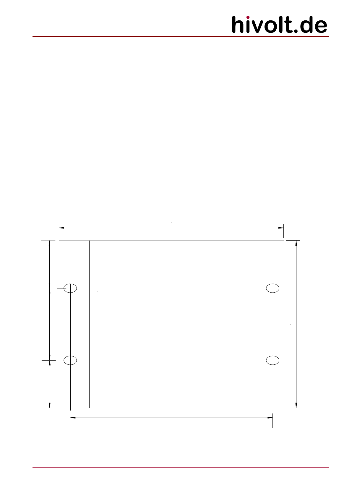
Sufficient space for ventilation must be kept below and above the unit when the HAR2-W is mounted.
5.6 Wall Mounting HAR2-W
178mm
132,50 mm
4x
10,2x7mm
160,20mm
37,7mm 57,1mm 37,7mm

15
hivolt.de GmbH & Co. KG
Oehleckerring 40 ∙D-22419 Hamburg ∙Germany ∙+49 40 537122-0 ∙+49 40 537122-99 ∙[email protected] ∙www.hivolt.de
5.7 Rack Mounting HAR12
The HAR12 Amplifier Subrack is designed to fit in a standard 19" equipment rack. Use the rack mount
brackets at both sides of the front panel to install the unit into a 19" rack.
5.8 Functional Test
Before the device is finally put into operation in a setup, a short functional test is to be carried out.
It is necessary that the interlock circuit is closed (HAR12S).
1. Make sure that the supply voltage is disconnected.
2. Remove all input signal cables and the output cable from the device.
3. Connect the terminals +24V_IL (INTERLOCK.2) and IL (INTERLOCK.3) by means of a wire
link.
4. Set all of the SETPOINT potentiometers to 10.0.
5. Set all input selector switches to REM.
6. Connect the unit to a grounded power outlet and turn the unit on (HAR12S);
connect the unit to a 24VDC power supply (HAR2)
7. Connect a 50ΩBNC-termination to the INHIB input at channel 1.
8. Select channel 1 (CHANNEL).
9. The voltage DVM should display about 0000 ±10;
the current DVM should display about 0000 ±10.
10. Set the input selector switch to MAN.
11. The voltage DVM should display about 500.0;
the current DVM should display about 0000 ±20.
12. Turn the SETPOINT-potentiometer to 0.
13. The output voltage changes from about +500V to about -500V.
14. Repeat the test with all the other channels.
15. Turn off the supply voltage.
5.9 Output connections
The outputs of the device supply a voltage of higher than 500V via SHV connectors. Connections to the
load should be provided only using connectors and cables with appropriate voltage rating.
Do not mate or unmate the output connector unless the device is switched off!
5.10 Output Connectors
Connector type: SHV
Connections to the loads should only be made using connectors and cables with appropriate voltage
rating.
The high voltage connectors may only be mated or unmated when the supply voltage is switched off!
Otherwise, there is a risk of an electric shock.

16
hivolt.de GmbH & Co. KG
Oehleckerring 40 ∙D-22419 Hamburg ∙Germany ∙+49 40 537122-0 ∙+49 40 537122-99 ∙[email protected] ∙www.hivolt.de
5.11 External Connectors
Signals: BNC
HV Outputs: SHV
Power line: IEC320-1 (HAR12S)
Earth: Bolt M4 (HAR12S)
Power supply: 2 pole Phoenix Combicon Connector (HAR2, HAR2-W)
Mating connector: 2 pole Phoenix Combicon Plug MSTB 2.5/2-ST-5.08
5.12 Internal Connectors
Internal connectors for HA05B2 plug-in modules (DIN41612, Type F)
Pins Signal
D2 B2 Z2 +VHV (+540V)
D4 B4 Z4 GND
D6 B6 Z6 VO (Amplifier output)
D8 B8 Z8 GND
D10 B10 Z10 -VHV (-540V)
D12 B12 Z12 GND
D14 B14 Z14 n.c.
D16 B16 Z16 n.c.
D18 B18 Z18 Internal connection, do not connect
D20 B20 Z20 Internal connection, do not connect
D22 B22 Z22 Internal connection, do not connect
D24 B24 Z24 Internal connection, do not connect
D26 B26 Z26 Internal connection, do not connect
D28 B28 Z28 Internal connection, do not connect
D30 B30 Z30 +VS (+24V)
D32 B32 Z32 GND
5.13 Grounding
The M4 ground bolt on the back panel of the device must be connected to the central grounding point
of the test setup and to protective earth (HAR12S).
17
hivolt.de GmbH & Co. KG
Oehleckerring 40 ∙D-22419 Hamburg ∙Germany ∙+49 40 537122-0 ∙+49 40 537122-99 ∙[email protected] ∙www.hivolt.de
5.14 Troubleshooting
If the device behaves unusual or erratic, please switch off the supply voltage and check the wiring of
the load and that of the control and monitoring signals. Check the connected load and the signal
source. Check the interlock circuit.
Do not attempt to locate any faults within the device. This can be dangerous to life due to the high
voltage used in the device. In such a case, please return the device to the manufacturer after
consultation.
Symptom Possible causes
Device will not turn on;
DVM displays will not light up
-No supply voltage present
-Fuses F1, F2 in the IEC inlet defective (HAR12S)
Output signal is distorted -Load capacitance too large for the desired slew rate
(see section 3.5 for load conditions)
Power supply and input signal
present but no output signal
-Examine the level of INHIB input signals
5.15 Maintenance
Depending on the cleanliness of the ambient air dust may accumulate within the unit possibly blocking
the airflow. In that case the accumulated dust has to be removed by taking out the amplifier modules
and blowing out the unit and the modules cautiously.
The manufacturer specified lifetime of the HAR12S fans is >50000h. After about 6 years of continuous
operation the fans might be replaced.
Type: Sunon MF60252V21000UA99
Caution: disconnect the unit from the power supply before removing any modules or opening any
covers.
Further regular maintenance is not required.
5.16 Cleaning
If necessary, wipe the device with a slightly damp cloth. Do not use abrasive detergents or solvents.
© hivolt.de GmbH&Co. KG, Hamburg, Germany
As of 07/2020
Document History:
Version Date Name Changes
1.0 10/2016 WM created
1.1 2020-07-16 WM updated layout and content

18
hivolt.de GmbH & Co. KG
Oehleckerring 40 ∙D-22419 Hamburg ∙Germany ∙+49 40 537122-0 ∙+49 40 537122-99 ∙[email protected] ∙www.hivolt.de
6Declaration of Conformity
We declare under sole responsibility that the products
Device: High Voltage Amplifiers
Series: HA05B2
Subrack: HAR12S, HAR2, HAR2-W
are in accordance with the following European directives:
Low Voltage Directive 2014/35/EU
EMC Directive 2014/30/EU
and comply with the following European standards:
EN 61010-1:2010 Safety requirements for electrical equipment for
measurement, control, and laboratory use -
Part 1: General requirements
EN 61326-1:2013 Electrical equipment for measurement, control and
laboratory use -
EMC requirements - Part 1: General requirements
Classification: Group 1, Class B
Manufacturer:
hivolt.de GmbH & Co. KG
Oehleckerring 40
D-22419 Hamburg
2016-10-04
Wulf Müller
Managing Director
This manual suits for next models
2
Table of contents
Other hivolt Amplifier manuals


