hivolt HA51U-3B2 User manual
1
hivolt.de GmbH & Co. KG
Oehleckerring 40 ∙D-22419 Hamburg ∙Germany ∙+49 40 537122-0 ∙+49 40 537122-99 ∙[email protected] ∙www.hivolt.de
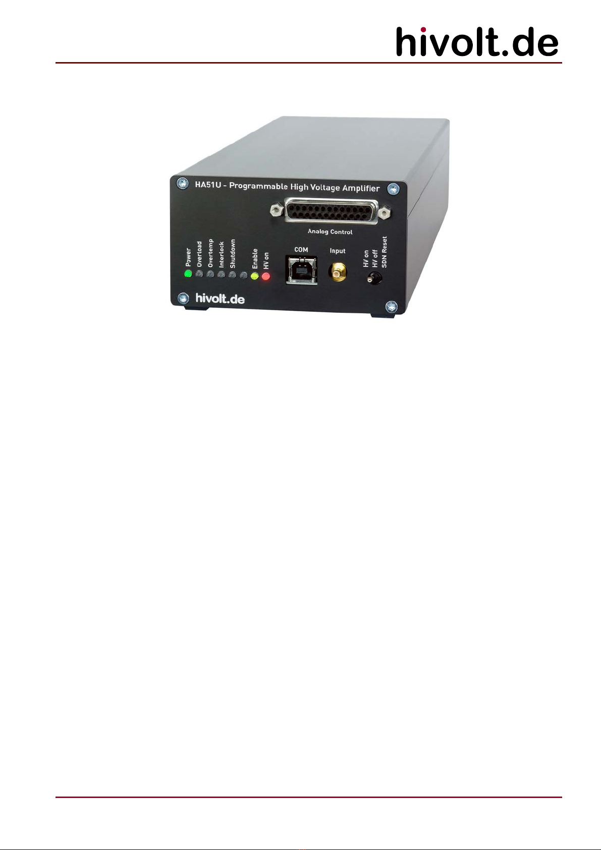
HA51U-3B2
High Voltage Amplifier
±3000V
Operating Manual

2
hivolt.de GmbH & Co. KG
Oehleckerring 40 ∙D-22419 Hamburg ∙Germany ∙+49 40 537122-0 ∙+49 40 537122-99 ∙[email protected] ∙www.hivolt.de
1WARNINGS 3
2DESCRIPTION 4
2.1 Block Diagram 5
2.2 Amplifier 5
2.3 Loading Conditions 6
2.4 Interlock 7
3TECHNICAL DATA 7
3.1 Ambient Conditions 8
3.2 Mechanical Specifications 8
4OPERATION 9
4.1 Check After Delivery 9
4.2 Warning Notices 9
4.3 Temperature Compensation 9
4.4 Installation 10
4.5 Power Supply 10
4.6 Ventilation 10
4.7 Functional Test 11
4.8 Input Connection 11
4.9 Analog Control X1 12
4.10 USB / COM X3 13
4.11 Power / Interlock X4 13
4.12 Output Connector X7 13
4.13 Earthing 13
4.14 DIP Switch S3 14
4.15 LEDs 14
5HANDLING / MAINTENANCE 15
5.1 Configuration 15
5.2 Command Interface 16
5.3 COM Port 19
5.4 Programming 19
5.5 Troubleshooting 20
5.6 Maintenance 20
5.7 Cleaning 20
6DECLARATION OF CONFORMITY 21

3
hivolt.de GmbH & Co. KG
Oehleckerring 40 ∙D-22419 Hamburg ∙Germany ∙+49 40 537122-0 ∙+49 40 537122-99 ∙[email protected] ∙www.hivolt.de
1Warnings
Attention! This device produces dangerous voltage above 3000V.
Due to capacitive charging, it can still be present even after the device has been switched off!
Please respect the following rules before every start-up of the high voltage amplifier:
•The device should be operated only by skilled personnel, in accordance with the local regulations
and the instructions given in this manual.
•Before switching the unit on, the experiment set-up should be checked out, and safety should be
assured. High voltage areas have to be sealed off and secured.
•In case of suspected damage or malfunction, the device should immediately be put out of service,
and it should be secured against unintentional or accidental operation.
•To provide protection for personnel in case of unit failure, the safety ground must always be
connected! Local regulations about grounding should be taken into account.
•High voltages may still exist even after the switch-off of the device due to capacitive charge!
Capacitances connected to the outputs of the device can possibly remain charged to dangerous
voltages, even after switching off the device
•Before removing any covers disconnect the unit from the power supply!
•Before touching the output or working on the experimental setup, disconnect the unit from the
power supply!
•The device may only be operated as a component of an overall structure that fully complies with
the regulations for working with high voltage systems.
Personal safety must be given the highest priority!

4
hivolt.de GmbH & Co. KG
Oehleckerring 40 ∙D-22419 Hamburg ∙Germany ∙+49 40 537122-0 ∙+49 40 537122-99 ∙[email protected] ∙www.hivolt.de
2Description
The single-channel high voltage amplifier HA51U-3B2 with bipolar output voltage is designed to drive
capacitive and ohmic-capacitive loads.
The amplifier is characterized by high speed, good stability and low noise. Piezo elements,
electroactive polymers, electrorheological fluids, electrostatic deflecting electrodes and many other
loads can be driven by this amplifier easily.
Output voltages of -3000V to +3000V at load currents of up to ±2.5mA and >5mAPare provided. The
signal gain is 300, the input voltage range is -10V…+10V.
The output voltage can be monitored by a high-speed voltage monitor; a current monitor provides a
representation of the output current.
The amplifier’s output is protected against overload, short circuit, overtemperature, transient
overvoltage and high voltage flashover. The LEDs on the front panel indicate operation and error
statuses.
An isolated USB interface is provided, allowing the user to control the amplifier via a simple command
interface (output voltage setting, voltage and current back reading, readout of temperatures and other
operating parameters, amplifier configuration, I/O lines setting and readout, ...).
Alternatively, the internal microcontroller can be utilized to allow the user to run his own application
programs. For example, to generate simple, arbitrary waveforms. It is also possible to run more
complex applications. For this purpose, additional free I/O lines and a separate analog input are
provided.
The internal microcontroller can be programmed via the free Arduino IDE. The entire application
software of the amplifier is available as open source.
The HA51U is housed in a sturdy aluminium case. It can be operated as a tabletop unit or be built in a
device housing.
5
hivolt.de GmbH & Co. KG
Oehleckerring 40 ∙D-22419 Hamburg ∙Germany ∙+49 40 537122-0 ∙+49 40 537122-99 ∙[email protected] ∙www.hivolt.de
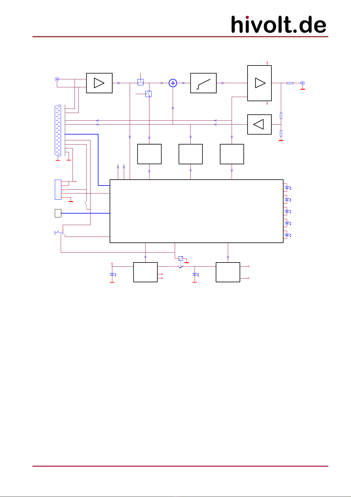
2.1 Block Diagram
+VHV
-VHV
HVON_M
NVA_ON
NVD_ON
A/D
VOAV
IOAV
GPIO, ENABLE, STAT US
X4
1
2
3
4
5
HV on
IL_R
Enable
Overload
Shutdown
Overtemp
Interlock
INP
INN
X2
SMB
Analog
Control
Input
X1
D-SUB 25
+VS
VOAV
IL_IN
S3-8
DIS_HVDIS_HV
DC/DC
+VS
A/D
IOAV
+VSFS+VDC
-15V
+15V
DC/DC
+VHV
-VHV
VONVA
HV on
HV off
SDN Reset
COM
HV Out
X7
SHV
CONTROLLER /
HOUSEKEEPING
NVA_ON
NVD_ON
X3
USB
VONV
+
GND
Interlock
SDN Reset
+24V In
Power /
Interlock
+24V Ilck
VONVD
S1
K1
-
D/A
VONVD
SDNRST_M
Power
VO
2.2 Amplifier
The device incorporates the high voltage amplifier itself, high voltage supplies for the output stage,
measuring functions, a microcontroller with a communication interface as well as monitoring and
protective functions.
The signal input is connected to a differential amplifier to avoid interference from ground loops. It is
available on SMB connector X2 and on X1 (Analog Control). It provides the analog setpoint VONVA.
Alternatively, the digitally generated setpoint VONVD can be used (command $ SV).
The amplifier has one voltage monitor output and one current monitor output. The VOAV voltage
monitor receives its signal via a compensated voltage divider and provides a scaled image of the
output voltages (10V V3000V). The frequency response is linear up to well above the upper cut-off
frequency of the amplifiers. The frequency response of the IOAV current monitor output is limited to
2kHz in order to filter out the ripple of high voltage sources.
The buffered monitor outputs are connected to X1 (output impedance: 10kΩ). They are able to drive
capacitive loads (coaxial cables), but are not designed to drive cables with a low-impedance
termination. They are short-circuit proof.
The monitor values can also be read using the commands $ RC,$ RP,$ RV.
6
hivolt.de GmbH & Co. KG
Oehleckerring 40 ∙D-22419 Hamburg ∙Germany ∙+49 40 537122-0 ∙+49 40 537122-99 ∙[email protected] ∙www.hivolt.de
During operation, the internal auxiliary supplies, overload of the high voltage sources, overtempera-
ture and interlock are monitored. In the event of a fault, the high voltage supplies are switched off and
the shutdown state is saved without interference. A shutdown state can only be exited by means of a
shutdown reset (S1 push button function SDN Reset,X1 SDNRST_D,X4 SDN Reset or command $ SR).
LED Function
Power on: 24V supply voltage
Overload on: overload
blink: shutdown due to overload
Overtemp on: overtemperature
blink: shutdown due to overtemperature
Interlock on: shutdown: interlock circuit open
blink: shutdown after interlock
Shutdown on: OFF state due to shutdown
Enable on: output stage is enabled by signal X1.ENABLE or
command $ EN1
HV on on: HV sources on
2.3 Loading Conditions
The amplifier channels are designed to drive capacitive and ohmic-capacitive loads. The output is
stable even with large capacitive loads
The slew rate that can be achieved for output voltage depends on the load capacitance. The effective
load capacitance CLconsists of the amplifier’s internal output capacitance (ca. 300pF), capacitance of
the output line (a typical coaxial cable: ca. 100pF/m) and capacitance of the connected load. The output
stage can provide peak currents (IOP) of > ±5mAPfor ca. 1ms. The maximum static output current is
+2.5mA and -2.5mA.
Achievable slew rate: SR = IO/ CL[V/s].
If the average positive or negative output current exceeds +2.5mA or -2.5mA, the amplifier shuts down
with Overload.
If the maximum slew rate is exceeded, distortions occur in the output signals. In principle, the
amplifier should thus only be controlled by input signals, that satisfy the achievable slew rate for a
given load. However, dynamic override of the inputs (e.g. control by square wave signals) is harmless.
The edges of the output waveform are nearly linear then with a slight overshoot.
Ohmic loads of ≥1200kΩcan be driven to the maximum output voltage.
At certain operating points (higher frequency at larger amplitude, higher load capacitance), the
amplifier temperature can rise to such an extent that the amplifier will switch off with Overtemp.
It is important to ensure that the amplifier is well ventilated. The internal temperatures can be
observed using the command $ RT. The switch-off threshold is around 80°C.
7
hivolt.de GmbH & Co. KG
Oehleckerring 40 ∙D-22419 Hamburg ∙Germany ∙+49 40 537122-0 ∙+49 40 537122-99 ∙[email protected] ∙www.hivolt.de
2.4 Interlock
The device incorporates an interlock circuit through which the supply voltage of the high voltage
sources is switched. It is a closed circuit with three switching points (break contacts). Its source
voltage is 24 V (carried out via +24V Ilck), quiescent current is 10mA. The switching points are:
1. Connector X4 Power / Interlock:
with terminals +24V Ilck and Interlock, the device can be looped into an interlock circuit
(potential-free break contact); these terminals must be connected together in order to allow
the high voltage sources in the device to be switched on;
2. Connector X1:
with IL_IN (X1.3) and IL_R (X1.16) the device can be looped into an interlock circuit (potential-
free break contact); if these pins are not used, they can be bridged using the DIP switch in the
device;
3. Lever key HV on / HV off on the front panel.
Only if all three contacts are closed, the supply voltage of the high voltage sources will be switched
on. The device will then still be in the Interlock shutdown state. The high voltage generation is not
functionally activated till the Interlock shutdown state is finished by Shutdown Reset.
The HV on display indicates that the supply voltage of the high voltage sources is switched on.
The device must be disconnected from its power supply before carrying out any works on the test
set-up or before touching the output terminals.
3Technical Data
Parameter Conditions
Supply voltage, VS24VDC ±10%
Supply current, ISVS= 24V <1.6ADC
Input voltage range Control input -10.0V – +10.0V
Max. input voltage ±18V
Input resistance 50kΩ
Gain 300 ±1%
Offset ≤200mV
Output voltage range -3000V – +3000V
Load current range static -2.5mA – +2.5mA
Load current range dynamic, t < 1ms -5mA – +5mA
Power bandwidth CL= 100pF, VO = 6000VPP,
THD ≤1%
DC – ≥1kHz
Bandwidth CL= 100pF, VO = 600VPP -3dB DC – ≥10kHz
Slew-Rate CL= 100pF ≥15V/μs
Internal output capacitance < 300pF
Ripple, Noise CL= 100pF; 1Hz – 20kHz ≤150mVRMS
Scaling monitor output V 10V V3000V ±1%
Bandwidth monitor output V DC – ≥20kHz
Scaling monitor output I 10V V10mA ±1%
Bandwidth monitor output I DC – ≥2kHz
-Signal ground and high voltage ground are connected to the chassis ground / earth terminal.
8
hivolt.de GmbH & Co. KG
Oehleckerring 40 ∙D-22419 Hamburg ∙Germany ∙+49 40 537122-0 ∙+49 40 537122-99 ∙[email protected] ∙www.hivolt.de
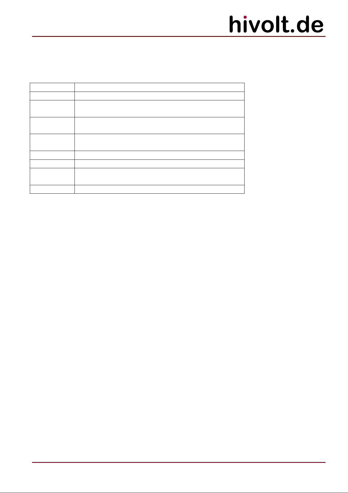
3.1 Ambient Conditions
Parameter Conditions Min. Max. Unit
Ambient temperature
- Operation
- Storage and Transportation
-20
-25
+50
+70
°C
°C
Relative humidity
- Operation
- Storage and Transportation
Not condensing
5
5
80
95
%
%
-Depending on the ambient temperature, modulation amplitude and load capacitance, the maximum
power may need to be derated.
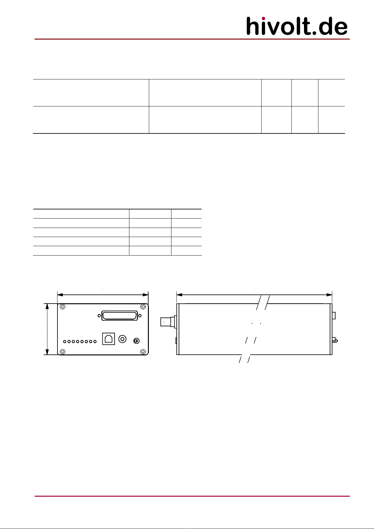
3.2 Mechanical Specifications
Parameter Typ. Unit
Depth overall * 250 mm
Depth case 225 mm
Width 105 mm
Height 59.3 mm
Weight 1.2 kg
*Depth overall without connection cables plugged in.
105.0 225
59.3

9
hivolt.de GmbH & Co. KG
Oehleckerring 40 ∙D-22419 Hamburg ∙Germany ∙+49 40 537122-0 ∙+49 40 537122-99 ∙[email protected] ∙www.hivolt.de
4Operation
4.1 Check After Delivery
Once the product is delivered, please check the packaging and the device for possible transport
damage. Please check the device taken out of the packaging for any mechanical defects before the
unit is put into operation.
If the device has any signs of damage caused by transport, please immediately inform the shipping
company so that damages can be claimed.
4.2 Warning Notices
-For safe operation of this device, it should be put into operation by a qualified electrician
according to this Operating Manual.
-The device may only be operated as a component of an overall structure that fully complies with
the regulations for working with high voltage systems.
-Output connectors may only be touched when the device is disconnected from the power supply!
Otherwise, there is a risk of electric shock.
-The test set-up must be fully wired and protected against any contact before the device is put into
operation.
-The test set-up must be checked each time before the device is put into operation to ensure that it
is not potentially dangerous. It should be checked that the high voltage connections are faultless
and the wire insulation is not damaged.
-The high-voltage areas must be blocked in accordance with regulations or otherwise secured.
-Once the test set-up is connected, any existing capacitances can be charged to high voltage. They
may carry dangerous voltages even after the device is switched off.
-The earth bolt on the back panel of the device must be connected to the central earthing point of
the test set-up and to protective earth. Local regulations on earthing must be observed.
-If it is suspected that safe operation is no longer possible, the device is to be taken out of
operation and secured against unintentional operation.
This symbol on the output terminals warns of the risk of electric shock.
This symbol on the case warns of potentially hot surfaces.
4.3 Temperature Compensation
To avoid condensation within the device, it should be allowed to reach the room temperature. Please
unpack the product at least two hours prior to power-up.
10
hivolt.de GmbH & Co. KG
Oehleckerring 40 ∙D-22419 Hamburg ∙Germany ∙+49 40 537122-0 ∙+49 40 537122-99 ∙[email protected] ∙www.hivolt.de
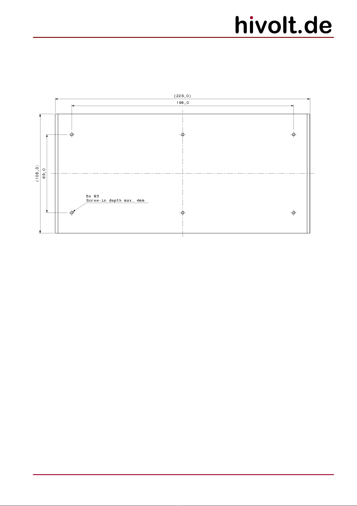
4.4 Installation
The device can be used as a tabletop unit or installed in a device housing.
At the bottom of the housing there are six M3 threaded holes for the in-housing installation. The
maximum screw-in depth is 4mm! When installing the device, please remove the rubber feet.
4.5 Power Supply
The device requires an external DC voltage source of 24VDC / min. 1.6A as the power supply. The
connection is made via the X4 Power / Interlock connector at the +24V In and GND pins.
Caution: Before you turn on the voltage source, please check its output voltage. Admissible range:
+24VDC ±10%. If the amplifier is operated with wrong supply voltage, it could become damaged.
4.6 Ventilation
Sufficient ventilation is required to remove the heat dissipated inside the case during operation (PDof
up to 36W). For tabletop operation, free flow of air is required. Active ventilation could be useful,
depending on the working point and ambient temperature.
If built into a device housing, the thermal losses can be removed through the structure of the housing,
if its design allows for this. Otherwise, active ventilation is required.

11
hivolt.de GmbH & Co. KG
Oehleckerring 40 ∙D-22419 Hamburg ∙Germany ∙+49 40 537122-0 ∙+49 40 537122-99 ∙[email protected] ∙www.hivolt.de
4.7 Functional Test
Before the device is finally put into operation in a test set-up, a short functional test is to be carried
out. For this purpose, it is necessary that the interlock circuit is closed.
1. Make sure that the supply voltage is disconnected.
2. Remove all input signal cables and the output cable from the device.
3. Connect the terminals X4 +24V Ilck and Interlock with the aid of a wire link.
4. Connect the supply voltage.
5. The Power, Shutdown and Enable LEDs will light up.
6. Activate the SDN Reset push button of the S1 switch and set the switch to HV on.
7. The Power, Enable and HV on LEDs will light up, the other LEDs will not.
8. Set the switch to HV off.
9. The HV on LED will turn off.
10. Disconnect the supply voltage.
11. Open the interlock bridge at X4.
12. Connect the supply voltage again.
13. The Interlock LED will light up.
14. Press the SDN Reset push button.
15. The interlock status remains unchanged and the high voltage cannot be switched on.
16. Turn off the supply voltage.
4.8 Input Connection
The amplifier features a differential signal input. If the signal generator has single-ended outputs, the
reference signal shall be grounded on the generator side.
The analog control signal can be fed via the SMB connector X2 or the D-Sub connector X1.
The input differential amplifier can be adapted to signal sources with 50Ωoutput impedance or low
output impedance. The characteristic can be changed using the command $ SS.
12
hivolt.de GmbH & Co. KG
Oehleckerring 40 ∙D-22419 Hamburg ∙Germany ∙+49 40 537122-0 ∙+49 40 537122-99 ∙[email protected] ∙www.hivolt.de
4.9 Analog Control X1
Connector type: D-Sub 25-pin female connector
Screwlock: UNC 4-40
Pin Signal Direction Function
1 +VS_IN I Supply voltage +24VDC
2 +VS_IN I Supply voltage +24VDC
3 IL_IN I Interlock / bridge to X1.IL_R
4 SDNRST_D I Control signal: TTL-H for 0.5s => Shutdown Reset;
Caution: This reactivates the HV output after a shutdown!
5 STAT1 O Status output; 5V level; RO= 1kΩ; H == no shutdown
6 INP I Differential analog input; positive
7 VOAV O Analog output: voltage monitor
8 IOAV O Analog output: current monitor
9 GPI1 I Digital input; TTL level
10 GPI2 I Digital input; TTL level
11 GPI3 I Digital input; TTL level
12 GPI4 I Digital input; TTL level
13 +5VX O Auxiliary voltage output +5V; max. 10mA
14 GND - Supply voltage GND
15 GND - Supply voltage GND
16 IL_R O Interlock / bridge to X1.IL_IN
17 ENABLE I Control signal: TTL-H => enables HV sources and output stages *;
Caution: This activates the HV output!
18 n. c.
19 INN I Differential analog input; negative
20 GND - Signal ground
21 X1_CTLn I Control signal: 5V level; L => function X1.ENABLE active;
internal pullup 10kΩ
22 GPO1 O Digital output; 5V level; RO= 1kΩ
23 GPO2 O Digital output; 5V level; RO= 1kΩ
24 GPO3 O Digital output; 5V level; RO= 1kΩ
25 GPO4 O Digital output; 5V level; RO= 1kΩ
*The ENABLE signal is only effective when the input X1_CTLn is set to L.
Switching the output off via the ENABLE control input must not be used as a safety-relevant
function!
ENABLE OFF -> ENABLE ON may not be switched faster than 5 s in each level, otherwise
shutdown will be triggered.
13
hivolt.de GmbH & Co. KG
Oehleckerring 40 ∙D-22419 Hamburg ∙Germany ∙+49 40 537122-0 ∙+49 40 537122-99 ∙[email protected] ∙www.hivolt.de
4.10 USB / COM X3
Connector type: USB B
The USB port COM is electrically isolated from GND to prevent ground loops (functional isolation).
When the USB cable is plugged in or unplugged during operation, or when the virtual COM port is
initialized by the operating system (for example, when being assigned to another application), a reset
is initiated and the device changes to the shutdown state. If this is disruptive, the reset signal coming
from the COM port can be interrupted via a DIP switch (S3-6). In this configuration, however, no
software download (internal program update) is possible.
4.11 Power / Interlock X4
Connector type: Mini-Combicon, 5-pin
Mating connector: Phoenix Mini-Combicon, 5-pin, FK-MCP1.5_ 5-ST-3.81
Pin Signal Direction Function
1 +24V In I Supply voltage +24VDC
2 +24V Ilck O 24V output for interlock circuit; protected against overload
3 Interlock I Interlock / bridge to X4.+24V Ilck
4 SDN Reset I Control signal: 24V for 0.5s => Shutdown Reset;
Caution: This reactivates the HV output after a shutdown!
5 GND - Supply voltage GND
4.12 Output Connector X7
Connector type: SHV
The high voltage connector may only be mated or unmated when the supply voltage is switched off!
Otherwise, there is a risk of electric shock.
4.13 Earthing
The M4 earth bolt on the back panel of the device must be connected to the central earthing point of
the test set-up and to protective earth.
14
hivolt.de GmbH & Co. KG
Oehleckerring 40 ∙D-22419 Hamburg ∙Germany ∙+49 40 537122-0 ∙+49 40 537122-99 ∙[email protected] ∙www.hivolt.de
4.14 DIP Switch S3
Switch Function Default
S3-1 Free: Controller PD4
S3-2 Free: Controller PD5
S3-3 Free: Controller PD6
S3-4 Free: Controller PD7
S3-5 Free: Controller PG0
S3-6 Enable COM-Reset; ON => Enable ON
S3-7 Must always be OFF! OFF
S3-8 Disable X1 Interlock; ON => Disable ON
4.15 LEDs
LED Function
Power on: 24V supply voltage
Overload on: overload
blink: shutdown due to overload
Overtemp on: overtemperature
blink: shutdown due to overtemperature
Interlock on: shutdown: interlock circuit open
blink: shutdown after interlock
Shutdown on: OFF state due to shutdown
[NN] free LED to be controlled by user software;
Arduino standard LED, Arduino "Pin 13"
Enable on: output stage is enabled by signal X1.ENABLE or
command $ EN1
HV on on: HV sources on

15
hivolt.de GmbH & Co. KG
Oehleckerring 40 ∙D-22419 Hamburg ∙Germany ∙+49 40 537122-0 ∙+49 40 537122-99 ∙[email protected] ∙www.hivolt.de
5Handling / Maintenance
5.1 Configuration
The device can be operated in different configurations:
As a pure analog amplifier:
The interlock circuit must be closed and an analog setpoint must be supplied via X1 or X2.
High voltage is switched on and shutdown states are reset by S1.
Control and monitor signals are available at X1 for functional extension.
As an analog amplifier with digital control and measuring functions:
The interlock circuit must be closed and an analog setpoint must be supplied via X1 or X2.
High voltage is released by S1.
Configuration, control, shutdown states reset and measuring functions run through the
command interface.
Control and monitor signals are available at X1 for functional extension.
As an amplifier with digitally generated set value and digital control and measuring functions:
The interlock circuit must be closed. High voltage is released by S1.
Configuration, control, set value generation, shutdown states reset and measuring functions run
through the command interface.
Control and monitor signals are available at X1 for functional extension. The analog set value
input can be used as a universal analog input.

16
hivolt.de GmbH & Co. KG
Oehleckerring 40 ∙D-22419 Hamburg ∙Germany ∙+49 40 537122-0 ∙+49 40 537122-99 ∙[email protected] ∙www.hivolt.de
5.2 Command Interface
A simple command interface with recognizable ASCII commands using a request-response structure
has been implemented to control and monitor the amplifier. Each command is followed by a response.
Coding format:
Request: $<id><com>[pars]<cr>[<lf>]
Response: $<err><id>[pars]<cr><lf>
$ Start character: "$"
id 1AN Sequence Id: a free alphanumeric character (not "$"); the id is returned with
the response for identification of the command sequence
com 2A Command: two alpha characters
pars AN Parameter: [par[;par[;...]]]; optional, depending on the command.
Number format: [-]1234.56; leading zeros, decimal point and decimal places
optional.
Parameter separator: ";"
err 1N Error number
<cr> End of record: Carriage Return
<lf> End of record: Line Feed (optional)
Examples:
Request: $1SR<cr> Shutdown Reset; id=1
Response: $01<cr><lf> no error; id=1
Request: $2SV-2577.23<cr> Set Output Voltage: -2577.23V; id=2
Response: $02<cr><lf> no error; id=1
Request: $ GI<cr> Read General Purpose Inputs; id=" "
Response: $0 12<cr><lf> no error; id=" "; Input Pattern: 12 (0x0c)
Request: $5rt<cr> Read Temperatures; id=5
Response: $05357;423;615<cr><lf> no error; id=5; 35,7°C (PA1), 42,3°C (PA2), 61,5°C (DC)
Request: $1XY<cr> invalid command; id=1
Response: $91<cr><lf> unknown command; id=1
Error numbers:
9 unknown command
8 wrong number format
7 parameter too high
6 parameter too low
0 no error
17
hivolt.de GmbH & Co. KG
Oehleckerring 40 ∙D-22419 Hamburg ∙Germany ∙+49 40 537122-0 ∙+49 40 537122-99 ∙[email protected] ∙www.hivolt.de
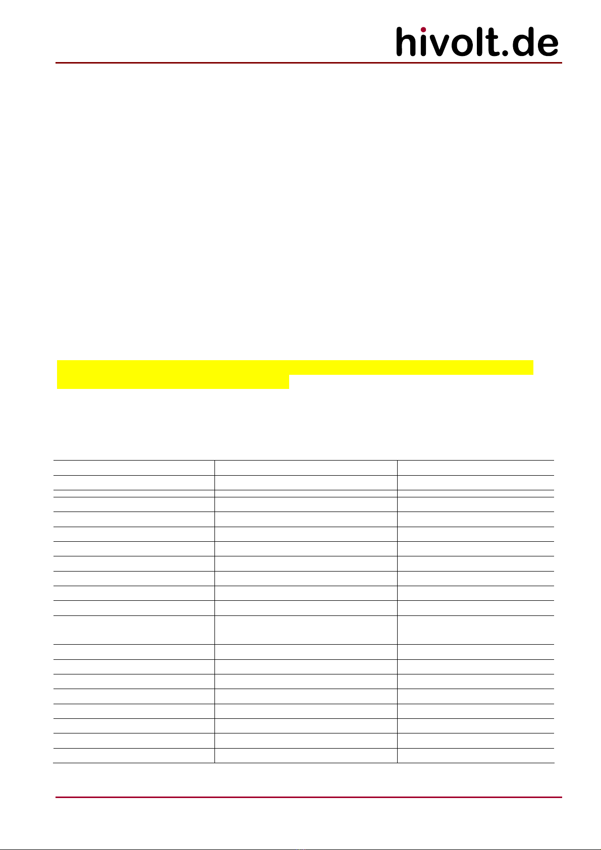
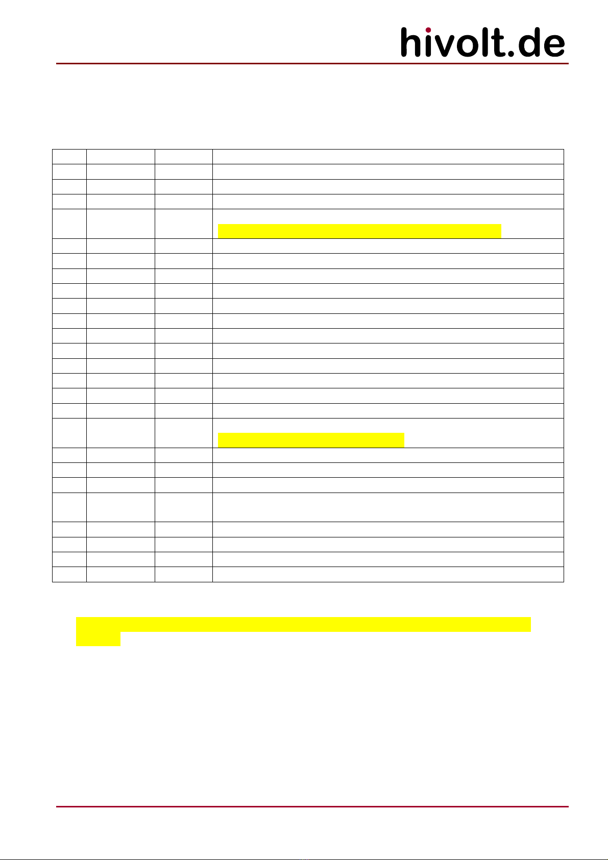
Command list:
Cmd Request
Param.
Response
Parameter
Function
EN 0,1 Enable HV and Amplifier
0: disable: HV sources functional off
1: enable (default): HV sources active
ES 0,1 Enable Amplifier Setpoint
0: disable: amplifier setpoint VONV = 0
1: enable (default): amplifier setpoint enabled
GI - 0…15 Read X1 General Purpose Inputs
Bit 0: GPI1
Bit 1: GPI2
Bit 2: GPI3
Bit 3: GPI4
GO 0…15 - Write X1 General Purpose Outputs
Bit 0: GPO1
Bit 1: GPO2
Bit 2: GPO3
Bit 3: GPO4
ID - <Model>
<Version>
Get Model ID / SW-Version
RA -
0…3000;
0…-3000;
0…10000;
0…-10000;
0…20000;
0…10000;
0…-20000;
0…20000;
-10000…
10000;
0…100;
0…100;
0…100
Read Aux Values
VHVPAV [V]: Actual value of positive HV supply voltage
VHVNAV [V]: Actual value of negative HV supply voltage
IHVPAV [μA]: Actual value of positive HV supply current
IHVNAV [μA]: Actual value of negative HV supply current
+VDC [mV]: Actual value of supply HV DC/DC converter
+5V [mV]: Actual value of +5.2V supply
-15V [mV]: Actual value of -15V supply
+15V [mV]: Actual value of +15V supply
VONVA [mV]: Actual value of analog setpoint
VT_PA1 [0,1°C]: Temperature of output stage pos. branch
VT_PA2 [0.1°C]: Temperature of output stage neg. branch
VT_DC [0.1°C]: Temperature of DC/DC converter
RC - -10000…
10000
Read Output Current
IOAV [μA]: Actual value of output current
RH -
0…3000;
0…-3000;
0…10000;
0…-10000
Read HV Source Values
VHVPAV [V]: Actual value of positive HV supply voltage
VHVNAV [V]: Actual value of negative HV supply voltage
IHVPAV [μA]: Actual value of positive HV supply current
IHVNAV [μA]: Actual value of negative HV supply current
RN - -10000…
10000
Read Analog Input
VONVA [mV]: Actual value of analog input signal (INP, INN)
RP -
3000…3000;
-10000…
10000
Read Output Voltage and Output Current
VOAV [V]: Actual value of output voltage
IOAV [μA]: Actual value of output current
18
hivolt.de GmbH & Co. KG
Oehleckerring 40 ∙D-22419 Hamburg ∙Germany ∙+49 40 537122-0 ∙+49 40 537122-99 ∙[email protected] ∙www.hivolt.de
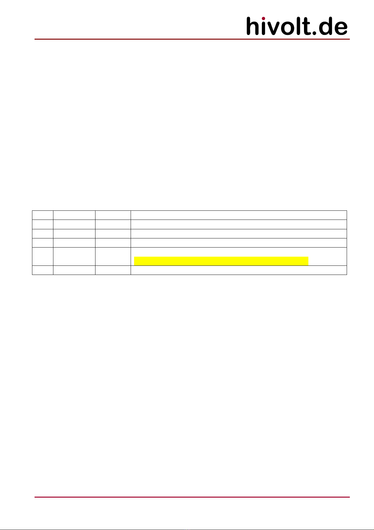
RS -
0…32767
Read Status
Status word (see below)
RT -
0…100;
0…100;
0…100
Read Temperatures
VT_PA1 [0.1°C]: Temperature of output stage pos. branch
VT_PA2 [0.1°C]: Temperature of output stage neg. branch
VT_DC [0.1°C]: Temperature of DC/DC converter
RV -
-3000…3000
Read Output Voltage
VOAV [V]: Actual value of output voltage
SD 0,1 - Select Setpoint Source
0: analog setpoint VONVA (default)
1: digital setpoint VONVD
SQ - - Shutdown Request
Set Shutdown Latch
SR - - Shutdown Reset
Reset Shutdown Latch
SS 0,1 - Select Analog Input Source Resistance
0: 0Ωsignal source output impedance
1: 50Ωsignal source output impedance (default)
SV -3000…
3000
Set Output Voltage Setpoint
VONVD [10mV]: digital setpoint; resolution 10mV
Status word:
Bit # Status bit Function
0 AXPWFAIL Aux Power Fail: Failure of auxiliary supplies +15V, -15V, +5.2V
1 IL Interlock loop open
2 IHV_OVR Overload Shutdown activated
3 T_OVR Overtemp Shutdown activated
4 SUM_SDN SUM Shutdown: Shutdown latch set
5 SDN_RST SUM Shutdown Reset signal active
6 DIS_SDNL Shutdown Latch deactivated
7 HV_ON High voltage active
8 HV_ON_M HV-ON switch S1 active
9 NVASL Analog Input (Setpoint) selected
10 NVEN Setpoint enabled
11 U4_ERR Pos HV Error
12 U5_ERR Neg HV Error
The status bits AXPWFAIL, IL, IHV_OVR, T_OVR, SUM_SDN, U4_ERR, U5_ERR are set when the
corresponding shutdown condition is present or has led to the shutdown.

19
hivolt.de GmbH & Co. KG
Oehleckerring 40 ∙D-22419 Hamburg ∙Germany ∙+49 40 537122-0 ∙+49 40 537122-99 ∙[email protected] ∙www.hivolt.de
5.3 COM Port
Communication takes place via a virtual COM port on the USB port COM. A USB-to-UART module FTDI
FT231X is used in the device for the conversion.
To communicate with an application (terminal program or application software) a hardware driver and
a driver for the virtual COM port is required. Using Windows, the drivers are normally installed
automatically. If this is not initiated automatically, you can also download the drivers from
http://www.ftdichip.com/Drivers/VCP.htm and install them manually.
In the Device Manager, entries are displayed under “USB Controller:USB Serial Converter” and under
“Ports (COM&LPT):USB Serial Port (COMxx)”.
The baud rate is set to 115 kBd. It cannot be changed.
Format: no parity bit, 8 data bits, 1 stop bit (N,8,1). End of line: <cr> or <cr><lf>.
The device can be directly controlled via the COM port using a terminal program or can be integrated
into a more complex application.
5.4 Programming
The device is controlled by an ATMEGA2560 microcontroller which operates at 16 MHz clock
frequency. The controller can be fully programmed by the user. The free Arduino IDE software is
suitable for this purpose. The entire application software of the amplifier is available for free usage.
The amplifier’s protection functions are independent of the controller and of the operation of the
application program.
20
hivolt.de GmbH & Co. KG
Oehleckerring 40 ∙D-22419 Hamburg ∙Germany ∙+49 40 537122-0 ∙+49 40 537122-99 ∙[email protected] ∙www.hivolt.de
5.5 Troubleshooting
If the device behaves unusual or erratic, please switch off the supply voltage and check the wiring of
the load and that of the control and monitoring signals. Check the connected load and the signal
source. Check the interlock circuit.
During operation various parameters are monitored and analyzed. In case of a fault the error is
reported via error LEDs on the front panel of the amplifier module. Press the SDN Reset to reset the
error condition.
Do not attempt to locate any faults within the device. This can be dangerous to life due to the high
voltage used in the device. In such a case, please send the device to the manufacturer after
consultation.
Symptom Possible causes
Device will not turn on; Power LED
will not light up
-No supply voltage present
HV on display will not light up -S1 switch is in HV off position
-Interlock circuit is open
-X1.ENABLE signal not set to H
-Enabling by command $ EN is switched off
Output signal is distorted -Load capacitance too large for the desired slew rate
(see section 2.3 for load conditions)
Amplifier switches off, the
OVERLOAD indicator lights up
-Dynamic load current exceeded (see section 2.3 for load
conditions)
-Static load current exceeded (see section 2.3 for load
conditions)
Amplifier switches off, the
OVERTEMP indicator lights up
-Poor ventilation
-Total load too large (see section 2.3 for load conditions)
5.6 Maintenance
Regular maintenance is not required.
5.7 Cleaning
If necessary, wipe the device with a slightly damp cloth. Do not use abrasive detergents or solvents.
© hivolt.de GmbH&Co. KG and WME Power Systems GmbH, Hamburg, Germany
Arduino is a protected trademark of Arduino LLC.
As of 10/2016
Document History:
Version Date Name Changes
1.0 2016-10-04 WM created
1.0 2016-10-11 WM corrections
1.0 2016-12-08 AR english version
Table of contents
Other hivolt Amplifier manuals


