Hix SubliPro User manual
Initial setup / installation ............................................................................2-7
Time & Temperature Control......................................................................... 8
Operation...................................................................................................... 9
Using Hix Sublimation Wraps................................................................ 10-11
Maintenance............................................................................................... 14
Notes for Substrates................................................................................... 15
Warranty ..................................................................................................... 16
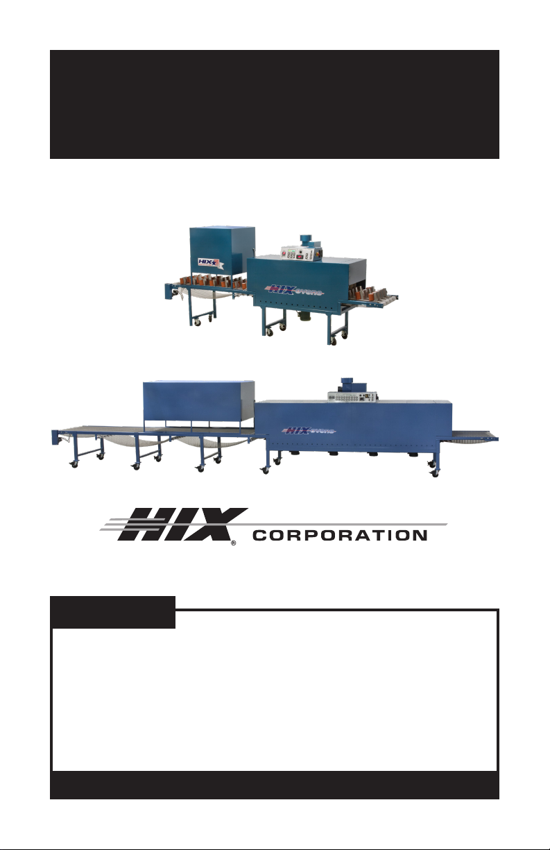
SubliPro
Sublimation Mug Oven with Cooler
OWNER’S MANUAL
BEFORE warranty repair you MUST get Prior Authorization:
For Customer Service, Call 1-800-835-0606
or Visit www.hixcorp.com
70138 RV J_120220
SubliPro-4827
SubliPro-2414
CONTENTS

2
INITIAL SETUP / INSTALLATION
INSTALLATION AND SET UP INSTRUCTIONS
1. Leg Assembly
A) Remove four nuts on inside of dryer frame that secures the dryer
to crate bottom.
B) Raise dryer from crate bottom with forklift to allow access to four
corner posts.
C) Insert legs to paint line.
D) Secure each leg bolt, lower forklift to allow dryer to rest on legs.
2. Top Exhaust Blower Motor
A) Secure housing to dryer top using provided #14 x 1/2” HEX head
tap screws with #14 Star Washer.
B) Attachblackwirestoexconduittancoloredwiresusingorange
wire nuts. Polarity is not important.
3. Bottom Blower Motor
A) Secure to bottom of dryer using 4 Greer lock nuts. Align point of
arrow in motor plate to point of arrow on bottom of dryer.
B) Match wire numbers of blower motor to ex conduit tan colored
wires using orange wire nuts. Polarity is not important. Also attach
the two green ground wires together.
4. Duct Work
A) Run duct from the exhaust stack on the dryer to the outside of
building. Install a rain cap to prevent water damage to the dryer.
Maximum duct length 30 feet ( 9 meters) from dryer to where it ex-
ists the building. If longer duct runs are required a booster fan must
be installed.
5. Extensions
A) If the oven is shipped to you crated, remove the extension and
cooler section from the crate and mount to the oven body.
B) Plug the gear motor and encoder plugs into their respective recep-
tacles on the exit end of the oven.
6. Conveyor Belt
A) Refer to the separate instructions supplied with the wire belt to
show the proper installation and splicing of the wire belt ends back
together.

3
INITIAL SETUP / INSTALLATION
1. Both the oven and cooler crates have du-
plex nails (pic 1) on all four sides which
need to be removed. This allows the top
to be removed at one time (either with
four people or by using a fork lift).
2. The oven section has two 3/8-16 hex
nuts directly under the door openings
(pic 2), which need to be removed.
3. Next, position the forks of the forklift
completely under the side frame rail (pic
3) until they protrude at the other end, ca-
pable of picking up the entire main body
of the oven. Once positioned and well
centered, lift the oven body up and off
the crate base.
4. Remove the legs from the bottom of the
crate and bolt them in the frame holes
(pic 4).
5. The bottom blower motor attaches with
four 3/8” NC locknuts (pic 5a) located in
a packet inside the control box.
pic 1
pic 1
pic 1
pic 1
pic 1

4
INITIAL SETUP / INSTALLATION
Red/white arrow decals should point toward each other when the con-
gurationiscorrect(pic5b).Similarlynumberedwiresconnecttogeth-
er with the orange wire nuts (also in pack)(pic 5c).
6. The exhaust fan assembly attaches to the top with ten #14 x ½” hex
head tap screws. (pic 6a). The wires to the assembly are not num-
bered and can be fastened either way with the orange wire nuts.
7. The cooler section has four 3/8” headed
lag screws to be removed before lifting
the unit off the crate base.
8. The 2414 model has only one set of legs (pic 8a) with angle iron tabs
on the exit side only. The entry side has arm extensions only (pic 8b).
Fasten the two sections together with the 3/8-16 x 1” bolts already in
the tabs.
pic 1
pic 1
pic 1
pic 1
pic 1
pic 1
pic 1

5
INITIAL SETUP / INSTALLATION
9. The 3626 model has two sets of legs on the exit side, both self-sup-
porting once installed. The 4827 model has 3 sets of self-supporting
legs.
The telescope tubing (pic 9a) slides into the oven frame until it hits the
metal stops (pic 9b and c). Next, tighten the four 9/16” headed bolts to
secure them together (pic 9d).
10. Insert the gear box quick-connectors into
the handy box, located under the oven’s
fume hood at the exit side. One connects
with a twist lock, the other with a snap
lock (pic 10).
11. The cooler unit’s wires are numbered to
match up with the wires in the electrical
handy box. Remove handy box cover,
run the wires and ex conduit into the
90˚ Romex connector and tighten the
screws. Tie the similarly numbered wires
together with orange wire nuts (pic 11).
Then replace the handy box cover.
pic 1
pic 1
pic 1
pic 1
pic 1
pic 1
6
INITIAL SETUP / INSTALLATION
12. To install the belt, place the rolled up belt under the cooler section on
theoor.Thebelt’sfrontis marked(pic 12a).Startfeeding thebelt
throughtheovenbyguidingitrstovertheidlerpulley(s)attheexit
side, then over the bottom rails (pic 12b, c). When arrived at the front
end of the oven, loop the belt up and back through the oven, all the
way back to the exit end.
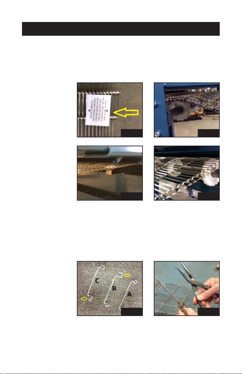
13. At the exit end, connect the two ends of the belt together with the pro-
vided belt splices. The splices are taped onto the belts edge. An extra
set is in the envelope with the belt.
Attention: there are 3 types of splices (pic 13a): one for the left end
(B), one for the right end (C) - both with one large and one small hook -
and one type for all center splices (A). The larger hook (yellow arrows)
is to be positioned on the outside edge of the belt.
pic 1
pic 1
pic 1
pic 1
pic 1
pic 1

7
INITIAL SETUP / INSTALLATION
Usingneedle-nosepliersandatheadscrewdriverworksbestwhen
weaving the link splices together (pic 13b, c and d).
14. When hooking up the electric connection to the main rotary switch,
be sure the wire connection is tight (pic 14a and b). Rotary switches
fail when this connection is no longer secure. Check periodically for
tightness.
pic 1
pic 1
pic 1
pic 1
8
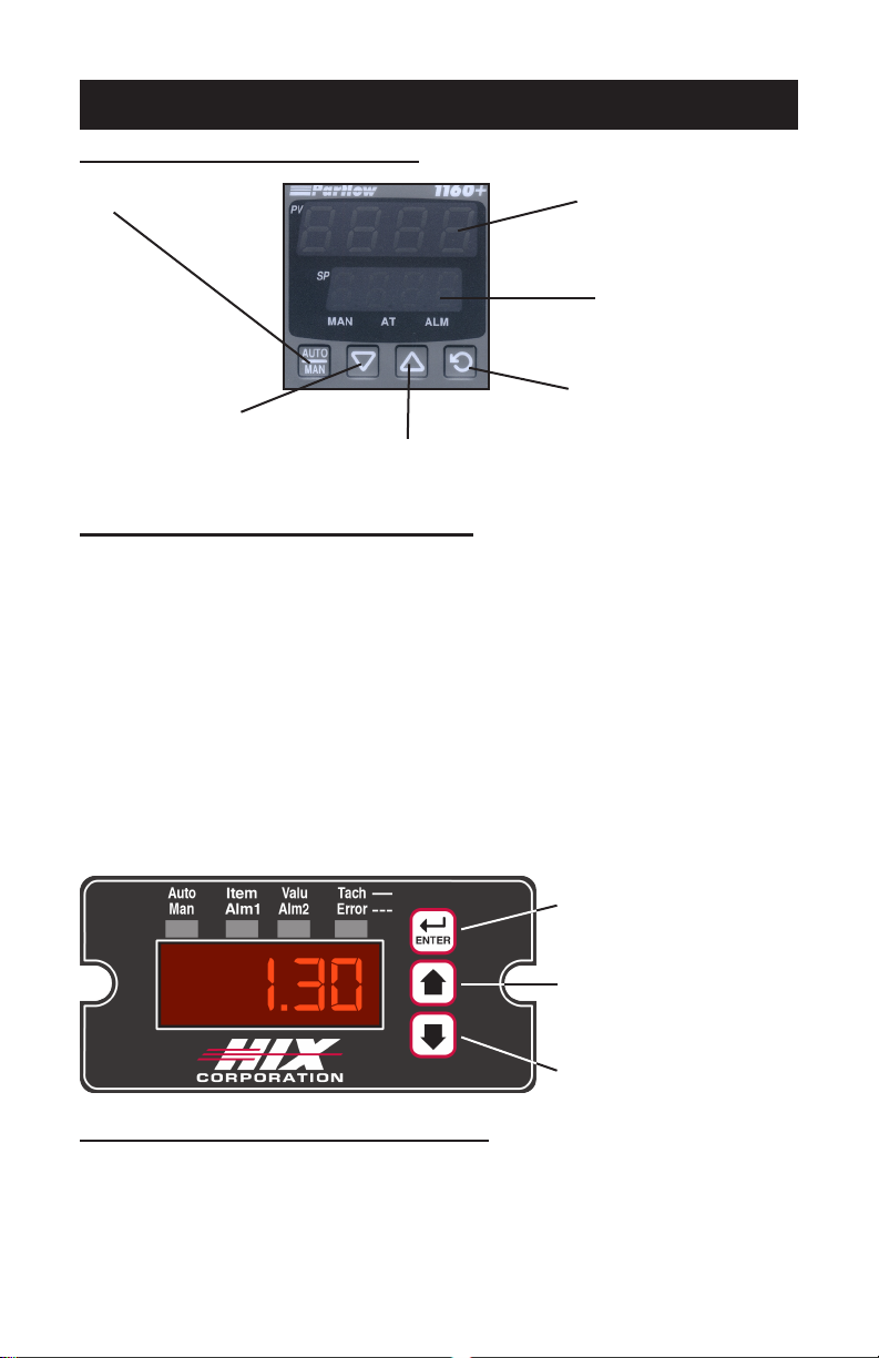
PROCESS TIME CONTROLLER
1. Controls belt speed and maintains a constant speed by monitor-
ing the motor RPM via a Hall-effect Sensor attached to the motor
shaft. Not effected by varying belt loads.
2. Displays process time in Minutes and Seconds.
Examples: 1.30 = 1 minute, 30 seconds
1.59 = 1 minute, 59 seconds
3. When the oven is turned off, the controller will remember the last
setting. Resetting the controller is not necessary each time the
dryer is turned on.
4. Function buttons detailed below:
RECIRCULATING AIR CONTROL
The dryer is equipped with a very effective top delivery/bottom recovery
variableowairrecirculatingsystem.Onezoneisprovidedonmodels
24”and36”beltmodels.Twozonesareprovidedon48”models.
TIME & TEMPERATURE CONTROL
TEMPERATURE CONTROL
Not functional.
Will decrease
setpoint (SP) when
“SP” is displayed.
Will increase setpoint (SP)
when “SP” is displayed.
Pressing this function button
once will allow “SP” to be
displayed enabling the opera-
tor to change the setpoint by
pressing the “up” and “down”
buttons located below. Press-
ing once again will return the
displays to their normal mode.
Lower display shows set-
point temperature.
Upper display shows cur-
rent value of process (oven)
temperature.
Nonfunctional
(factory only)
Decreases process time
(increases belt speed)
Increases process time
(slows belt speed)

9
OPERATION
OVEN OPERATION
General Oven operation for applying sublimation transfers to mugs, cups
and ceramic items. This information is for reference only and actual set-
tingswillvarydependingonimagequality,imagesize,thesizeofmugor
ceramic item, and quality of coating on item, ink and type of wrap being
used. It is very important that your dryer electric source is supplied with
the maximum voltage required; 240v ± 5v.
Your dryer may not operate to full potential if running below 235v. Electric
power does vary. Many power companies simply can not deliver consis-
tent power at ratings also power supply consumed in your grid by other
companies can cause intermittent and inconsistent power. Your power
company or electrician can assess your particular power supply.
TYPICAL TEMPERATURE SETTING:
370°-410°F
BELT SPEED.
Isdependentonimagesize,qualityofgraphicandsizetypeofink,paper
used and weight of object imaged. A general starting place is 11-13 min-
utes.
Typical Times with HIX Mug Wrap (Other wraps may take longer)
11ozMug………10-13minutes
15ozMug………11-18minutes
AIR SPEED
6-8 on dial.
OVEN SETUP AND SPACING;
Establishspacingbyrstusingscraporblankmugswithwrapandblank
paper (bond paper will work). If your oven does not maintain consistent
temperature (± 30°F) slow your oven down and/or increase spacing. Gen-
erally, running oven hotter will not help. In fact, items may get too hot and
scorch the image closest to the heater. Begin with items spaced at least
2” apart and 2” from side of dryer. Thicker/larger/heavier items will require
greater spacing.
APPLYING THE TRANSFER
With some wraps including the HIX tool-less “Snap” clasp wrap, you will
be able to image virtually top to bottom and handle to handle. While full top
to bottom and handle to handle imaging is possible it is not recommended
untilyouhavearmunderstandingandexperiencewithimagingmugs.
To achieve consistent results and reduce waste keep your transfer width
limited to 3/16” from the top rim and the bottom taper of the mug and at

10
USING HIX SUBLIMATION WRAPS
a) Hold the “loop end” of the mug wrap
in your hand.
b) Hold the mug with the handle
pressed against the “loop end” at
the point where the silicone rubber
wraps around the round bar.
c) With your other hand, grasp the
“hook end” of the mug wrap, and
wrap the silicone rubber around the
mug.
d) Insert the bent
up portion of
the “hook end”
into the rect-
angular open-
ing on the
“loop end.”
e) With both hands, squeeze the two
halves of the mug wrap together un-
til it locks together. You will hear a
‘snap’ sound
when the
“hook end”
is fully in-
serted into
the “loop
end”.
least a ¼” away from the handle you should see consistent quality. As you
become more experienced there are tips and tricks that will make full wrap
imaging more successful; not fool proof but more consistent results can be
achieved with proper preparation of the transfer. Also quality mugs must
be purchased, while a mug wrap helps to cover some imperfections in the
mug itself, nothing can help a poorly made, wavy or irregular surface and/
or coated mug.
TO USE YOUR WRAP
1. TRIM TRANSFER: Before applying the transfer trim the transfer so
there is no excess paper above or below the mug. TIP: Trimming the
transfer with a straight edge will assist in lining the transfer with the
top of the mug and help eliminate crooked transfers.
2. APPLY TRANSFER: Secure the ends of your transfer to the mug
using heat tape. TIP: Fold one end of the heat tape to make for quick
and easy removal of transfer.
3. WRAP MUG:
4. PLACE IN OVEN: Set oven to 400°F. Place your wrapped mugs
in the oven top down to allow heat to be trapped inside of the mug
improving transfer quality. Space each mug at least 2 inches apart
toallowformaximumairowbetweenmugsandmoreevenheating
of the entire mug.

11
USING HIX SUBLIMATION WRAPS
a) Remove mug from oven
b) Press thumbs against the bottom lip
of the “loop end.”
c) Pressindexngersagainst thetop
edge of the “hook end.”
d) With one motion, press thumbs up
andindexngersdown.Thiswillre-
lease the mug from the wrap.
e) Place mug in room temperature wa-
ter to cool mug and stop sublimation
process.
CAUTION: Wrap will be hot use care when applying wrap to another mug.
It is recommended to allow wrap to cool before using again.
INCREASING THE LIFE OF YOUR WRAP:
The following actions will increase the life of your wrap and help to prevent
premature failure.
- Space your mugs at least 2” apart in oven, this will allow for more
evenheatingandairowbetweenmugs.Alsothiswillpreventmugs
from banging together reducing the life of your wrap.
- Do not drop or bang mugs with wraps together. This can cause
small tears in your wrap leading to tearing of the wrap.
- Only use on items the wrap is rated for; the standard HMWIII is de-
signedforboth11ozand15ozmugs.Useofthesewrapsforanything
else may shorten the life of the wrap and could result in damage such
astearing.Forunusuallysizedorshapeditemspleaseutilizeawrap
custom made for your application.
- Sharpngernailsandringscansnare/tearawrap.
If the above procedures are followed and care is taken when handling these
wraps you should expect to get hundreds of cycles from your HMWIII.
5. REMOVE AND COOL:
CAUTION: Wearheatprotectiveglovestohandlethenishedwrapsand
mugs.

12
DIAGNOSTICS
HEATER AND RELAY LIGHTS
1. Heater LED’s: Cycle On When Heaters Are On
Small (1/8”) light-emitting diodes (LED’s) are driven by a current sensor
(one for each heater in the dryer). They can, in conjunction with relay
lights explained below, determine if heater(s) are burned out or if a relay
is at fault.
2. Relay Lights: Cycle Off When Heaters Are On
Large (1/4”) neon lights indicate proper opening and closing of each
heater relay. When relay lights are “on”, the relays are “open” and no
power is applied to the heaters (Heater LED’s Off). When relay lights
are “off”, the relays are “closed” and power is applied to the heaters
(Heater LED’s On). If one relay light stays “on” while the others are
off, then that pole is stuck “open” and should be replaced. The heater
LED’s will still function as normal as they are “double switched”.
NOTE: If all relay lights operated normally yet one of the heater LED’s will
not come on, check the suspected heater with an amp clamp. Normal
readingshouldbe9-12ampsdependingonelementsizeandvoltage
available.Ifreadingsindicatenocurrentowing,thentheheaterwill
require replacing.
ON
OFF
ON/OFF POWER BREAKER IN/OUT (I/O)
CIRCUIT BREAKERS
Turns all dryer power and
control circuits on and off.
Provides protection to con-
tactor coil only. Dryer MUST
be externally fused with ap-
propriatesizefuseorcircuit
breaker (FLA x 125% = fuse
size). See the following
sheet for fuse size to be
used for each dryer.
Provide protection
for control and
heater circuits only!
DO NOT use for
ON/OFF control! If
a breaker trips, de-
termine the cause
before resuming
operation.
OVEN OPENINGS
This oven is supplied with “Air Curtains” on
each end of the oven chamber.
They are designed to retain heat inside the
ovenchambertoimproveenergyefciency
and also eliminate air drafts from entering the
oven chamber resulting in better temperature
regulation.
Air Curtains

13
OPERATING PRECAUTIONS
GENERAL OPERATING PRECAUTIONS
While the below information will not cover every operating situation,
these guidelines should be understood and general common sense
applied when operating the equipment. Failure to do so could cause a
rehazard,explosionhazardandpossibleseriouspersonalinjuryor
death.
Intended Use:
HIX electric conveyor ovens may be used to cure or dry a number of
inks, substrates or products such as textiles, wood, plastic, glass or
any other similar substrates. The oven process temperature is to be
set within the safe temperature limitations of the ink or substrate. Re-
search of the temperature limitation of the particular ink or substrate is
solely the responsibility of the end user and not of HIX Corporation. HIX
Corporation will not be responsible for any damages to product, oven,
facilities or personnel caused by product being exposed to temperatures
exceeding their limitations or operating the oven in any manner in which
it was not intended.
Proper Venting:
Never block any of the air vents leading into or out of the control box.
Likewise never block any of the air vents located in the sheet metal
side covers along the lower frame rails. Blocking any of these vents
cancauseoverheatingoftheunitandcreatearehazard.Thetop
mounted exhaust on the oven shall be vented outside of the building.
See instructions in this manual for additional information on proper
venting of the exhaust.
Safe Operation:
Pay careful attention to the adjustable doors located on each end of the
oven. Ensure that the door on the exit end of the oven is raised higher
than that on the entrance end of the oven so there is no possibility that
product may get accumulated or lodged inside the oven chamber and
createarehazard.
Keep aerosol spray cans away from the oven. If they accidently fall on
the belt and enter the oven chamber they can overheat and explode
insidetheovenchambercausingarehazardandorpersonalinjury.
Neverintroduceanyammableliquidintotheoventoevaporate,such
as solvents, including, but not limited to alcohol, MEK, acetone, toluene,
etc.withoutconsultingthespecicapplicationwithHIXCorporationto
determine what amount can be safely introduced into the oven without
causingadangeroussituation.Failuretodosocancausere,personal
injury or death.

14
MAINTENANCE
MAINTENANCE SCHEDULE
Every month:
Removeandcleanorreplacelterslocatedoneachsideofcontrolbox.
Every 6 months:
1. Vacuum any lint/dust accumulation around air intake holes on both sides
of oven and on fume hoods.
2. Check tension on the wire conveyor belt and tighten if necessary.
Every Year: (Disconnect power at main panel)
1. Remove top chain guard cover and lightly lubricate the conveyor drive
chain; with SAE 20 weight oil. Replace after lubricating. DO NOT leave
off!
2. Haveaqualiedelectriciancheckallheaterelementstospecications
shown on wiring diagram.
3. Check brushes on conveyor drive motor.
4. Check/tighten all electrical connections on relays and contactor inside
control box.
6. Check thermocouples with ohm meter disconnected from temperature
control. Cold resistance should be between .5 to 2 ohms. Higher resis-
tance readings indicate possible problems with the thermocouple and
in this case it should be replaced.
TO ADJUST THE TENSION OF THE SILICONE RUBBER ON WRAPS:
When the mug wrap is closed around a mug, if the rubber is too loose
or too tight, loosen the two Phillips headed screws and adjust the rub-
ber length to achieve the desired tension. Re-tighten the screws to pro-
vide tension to hold the rubber in the wrap ends. Do not over tighten the
screws, as damage to the silicone rubber can result. (Pic 9)
TO REPLACE THE SILICONE RUBBER ON WRAPS:
If the rubber in the mug wrap has become damaged, or you are replacing
therubberforadifferentsizedmug,loosenthetwoPhillipsheadedscrews
and remove the rubber from the wrap ends. Thread the rubber between
the round bar and wrap itself. Re-tighten the screws to provide tension to
hold the rubber in the wrap ends. Do not over tighten the screws, as dam-
age to the silicone rubber can result.

15
NOTES FOR SUBSTRATES

16
(Effective 3/1/2020)
HIX will automatically register the equipment on the date it was shipped to you or your distributor. If the
equipment was not purchased directly from HIX, but through a distributor (either domestic or foreign), please
keep a copy of their sales invoice showing the serial number and date it was sold/shipped to you with this war-
ranty. In this case, we will use the distributor’s invoice date as the beginning warranty date. STAPLE A COPY
OFYOURPROOFOFPURCHASETOTHISWARRANTYandkeepinasafeplacetoprovidevericationof
your warranty should a problem occur. Thank you.
Pleasellinthefollowinginformationandattachacopyofyourreceiptforyourrecords.
Date Purchased: From:
Model #: Serial #:
This warranty applies to equipment manufactured by the HIX Corporation (HIX), Pittsburg, Kansas, U.S.A.
HIX warrants to the original purchaser, its Ovens and Dryers, Heat Transfer Machines, Textile Printers, Spot
Heaters, and Exposure Units against defects in workmanship and material, except for wear and tear for a
period of “One Year” from the date of purchase. HIX warrants Accessories for a period of 90 days from the
date of purchase. doughXpress products are covered under separate warranty.
In the event of a defect, HIX, at its option, will repair, replace or substitute the defective item at no cost
during this warranty period subject to the limitations of insurance and shipping costs stated below (excludes
labor).
In the case of heat transfer presses (except the Hobby Lite and Large Format presses), HIX warrants the
heat casting for the “Life” of the machine for the original purchaser. If a part becomes obsolete at the time
for repair, and/or cannot be reasonably substituted for, HIX will credit, at half the then current list price or last
recorded price, only that part toward a new machine or any product HIX offers. This credit offer shall be the
sole responsibility of the HIX Corporation in the event of an obsolete part.
This warranty does not cover belts, rail tape, pads, mug wraps, canvas, rubber blankets, bulbs, glass.
Warranty does not cover damages due to accident, misuse/abuse, alterations or damage due to neglect, ship-
ping or lack of proper lubrication or maintenance. HIX shall not be responsible for repairs or alterations made
byanypersonwithoutthepriorwrittenauthorizationbyHIX.Thiswarrantyisthesoleandexclusivewarranty
ofHIXandnoperson,agent,distributor,ordealerofHIXisauthorizedtochange,amendormodifytheterms
set forth herein, in whole or in part.
Inthecaseofaproblemwiththeequipmentidentiedherein,HIXCorporationshouldbecontactedduring
regular business hours to discuss the problem and verify an existing warranty. HIX personnel will assist the
customer to correct any problems which can be corrected through operation or maintenance instructions,
simple mechanical adjustments, or replacement of parts. In the event the problem cannot be corrected by
phone,andupontheissuanceofareturnauthorizationbyHIX,theequipmentshallbereturnedtoHIXoran
authorizedservicerepresentative.Allinsurance,packagingandshipment/freightcostsaresolelytherespon-
sibility of the customer, and not that of HIX, and HIX shall not be responsible for improper packaging, handling
ordamageintransit.ContactHIXcustomerserviceforcompletereturnauthorizationinformation.Correct
shipping boxes are available from HIX.
This expressed warranty is given in lieu of any and all other warranties, whether expressed or implied,
includingbutnotlimitedtothoseofmerchantabilityandtnessforaparticularpurpose,andconstitutesthe
only warranty made by HIX Corporation.
In no event shall HIX’s liability for breach of warranty extend beyond the obligation to repair or replace the
nonconforming goods. HIX shall not be liable for any other damages, either incidental or consequential, or the
action as brought in contract, negligence or otherwise.
Thiswarrantygivesyouspeciclegalrightsandyoumayalsohaveotherrightswhichvaryfromstateto
state.
WARRANTY
1201 E. 27th Terrace • Pittsburg, KS 66762 • U.S.A.
Web site: www.hixcorp.com • Phone: (800) 835-0606 • Fax: 620-231-1598
©2020 HIX Corp.
Design and Manufacturers of Graphic Imaging, Commercial Food, Industrial and Custom Drying Equipment
This manual suits for next models
3
Table of contents
Other Hix Oven manuals


Popular Oven manuals by other brands

Bauknecht
Bauknecht ESZH 5964 Product description sheet

Bosch
Bosch HBG78R950B installation instructions

Aroma
Aroma ART-722SB instruction manual

Dacor
Dacor Renaissance MORD230 use and care manual

GIERRE
GIERRE BAKETEK Series Instructions for installation, use and maintenance

Middleby Marshall
Middleby Marshall PS360 SERIES Owner's operating & installation manual


