HMC Glider 633 User manual

Note:
keep this manual for future reference.
Whole Body Exercise


- Contents -
1. Contents ---------------------------------------------------------------
2. Safety Instructions---------------------------------------------------
3. Assembly Instructions ----------------------------------------------
(1) Parts In Carton----------------------------------------------------
(2) Tool & Screw Kits------------------------------------------------
(3) Assembly Steps--------------------------------------------------
5. Console Functions---------------------------------------------------
6. Trouble Shooting & Maintenance---------------------------------
7. Training Stages--------------------------------------------------------
7. Warm Up Exercise---------------------------------------------------
8. Exploded Drawing----------------------------------------------------
9. Part List------------------------------------------------------------------
2
P2
P3
P4
P4
P5
P6-17
P18-19
P20
P21
P22
P23
P24-25

- Safety Instrucons -
3
Thank you for choosing HMC 633 Glider Trainer,please read the
instrucons before assembling and using the machine.
Read all the instrucons in this manual and do warm up exercises beforeusing this
equipment.
Before using this equipment, please consult your physician for a complete physical
examinaon. If you feel any discomfort while exercising, please stop immediately and
consult your doctor.
Before exercising and to avoid injuring your muscles, perform warm-up exercise for each
muscle group is highly recommended. Please refer to Warm Up secon of the Owner’s
Manual.
Keep the equipment indoors, away from moisture and dust. Place the equipment on a
level surface, with a mat beneath it to protect the floor or carpet. Make sure that there
is enough clearance around the equipment to mount, dismount, and use it.
Inspect and properly ghten all parts regularly. Replace any worn parts immediately.
Ensure that your fingers or clothing do not catch in the equipment moving parts.
Please keep children and pets away from the equipment at all mes. It is only suitable
for adults.
The equipment should not be used by persons weighng more than 120 kg. Serious
injury may occur if the user’s weight exceeds the limit shown here.
If you hear unusual noise when exercising, please stop your training immediately.
Do not use the equipment unl the problem has been resolved.
Do not touch the flywheel right aer the training.

- Assembly Instrucons -
4
Please check all the parts you need before assembling the bike.
Before completely assemble the equipment, please do not throw away the package.
Pleae assemble based on the Assembly Steps.
1. Main Frame 2.Up right Tube 3. Fixed Handlebar 4. Upper Swing Bar(L/R) 5. Lower Swing Bar(L/R)
6. Pedal Tube(L&R) 7.Wheel Tube(L&R) 9. Rear Stabilizer 10. Front Stabilizer
27. Console 40. Swing Bar Cover
43. Lower Swing Bar Cover 49. Pedal(L&R) 71. Bole Holder Tool Kits Manual
35. Adopter
Parts
20. Pedal Tube Axle 46. Swing Axle Cover
Manual

5
#61 x 4pcs
Axle Side Cover
#76 x 4pcs
Carriage Bolt
M8x55mml
#80 x 8pcs
Hex Socket Head Bolt
M8x18mml
#82 x 4pcs
Hex Socket Head Bolt
M8x42mml
#84 x 2pcs
Hex Socket Head Bolt
M10x68mml
#85 x 4pcs
Cup Head Bolt
M6x20mml
#90 x 6pcs
Self-Tapping Screw
M4.5x15mml
#93 x 4pcs
Washer 8x21x2.0T
#94 x 8pcs
Washer 6x14x1.0T
#95 x 4pcs
Washer 8x16x1.5T
#96 x 4pcs
Washer 8x25x2.0T
#97 x 2pcs
Washer 10x19x1.5T
#98x 2pcs
Washer 19.5x38x2.0T
#100 x 2pcs
Wave Washer 19x23x0.2T
#118 x 2pcs
Wave Washer
16.2x25x0.5T
#111 x 2pcs
Nylon Nut M10
#110 x 8pcs
Nylon Nut M8
#109 x 4pcs
Nylon Nut M6
the equipment.
- -
Tool Kits
Tools:
#A x 2pcs
Allen Wrench 5mm
#B x 1pc
Philips Screwdriver&Wrench 10.14.17mm
#C x 1pc
Philips Screwdriver&Wrench13.14.15
#119 x 2pcs
Washer 8x38x2.0T

- Assembly Instrucons -
6
#95 x 2pcs
Washer 8x16x1.5T
#110 x 2pcs
Nylon Nut M8
Let’s assemble -
Step1:Assemble the Front Stabilizer
-Remove Carriage Bolt(#76)、Wahser(#95) & Nut(#110) from the
tool kits(2pcs each),
-Assemble the Front Stabilizer(#10) to the Main Frame(#1)
As shown in Figures.
1
10
#76 x 2pcs
Carriage Bolt M8x55mml
C
67
7
Carriage Bolt
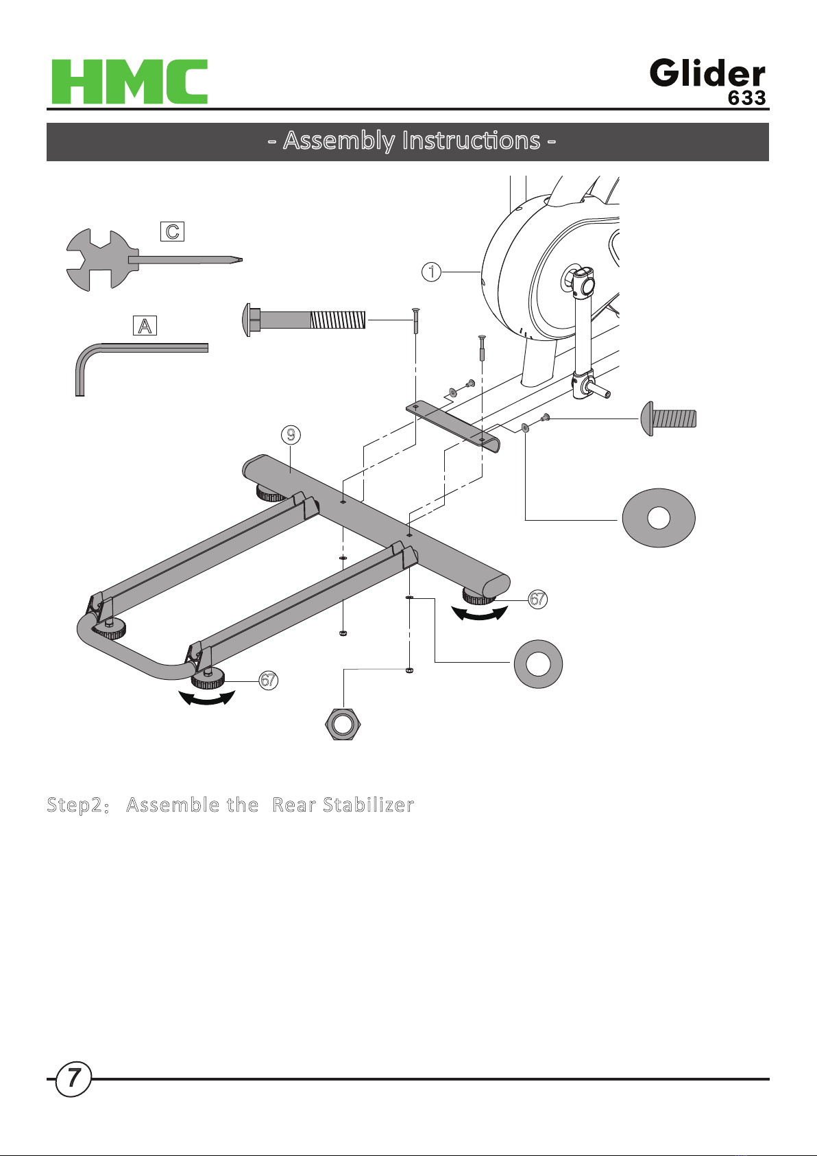
Step2:Assemble the Rear Stabilizer
- Remove the Hex Socket Head Bolt(#79-2PCS)&Curved Washer(#102-2PCS) from
the Rear Stabilizer(#9)
- Remove the Carriage Bolt(#76-2pcs),Washer(#95-2pcs)& Nut(#110-2pcs) from the
Tool Kits, assemble the Rear Stabilizer(#9) to the Main Frame(#1)
- Screw back Hex Socket Hear Bolt sets(2 sets) back to the Rear Stabilizer(#9).
Noce:
If the floor is not even, please adjust the Adjustable Stand(#67) to stabilize the equipment.
9
1
#79 x 2pcs
Hex Socket Head Bolt
M8x20mml
#102 x 2pcs
Curved Washer 8x21x2.0T
C
A
67
67
- Assembly Instrucons -
#76 x 2pcs
Carriage Bolt M8x55mml
#95 x 2pcs
Washer 8x16x1.5T
#110 x 2pcs
Nylon Nut M8

8
#78 x 6pcs
Hex Socket Head Bolt
M8x15mml
#102 x 6pcs
Curved Washer
8x21x2.0T
#103 x 6pcs
Spring Washer
Step3: Assemble the Up Right Tube(#2):
- Remove the pre-assembled Hex Socket Head Bolt(#78),Spring Washer(#103) &
Curve Washer(#102)--6 sets.
- Place the Up Right Tube Cover(#42) onto the Up Right Tube(#2),
then connect the Cable(#30+#31) correctly.
- Assemble the Up Right Tube(#2) to the Main Frame(#1), screw back the Hex Socket Bolt
sets you just removed.
Noce!!! Do Not Tighten the Screw Unl the Equpiment is Fully assembled.
2
30
42
31
31
30
1
A
- Assembly Instrucons -
- Assembly Instrucons -
9
3
27
30
30
2
28A
28B
28A
28B
28B
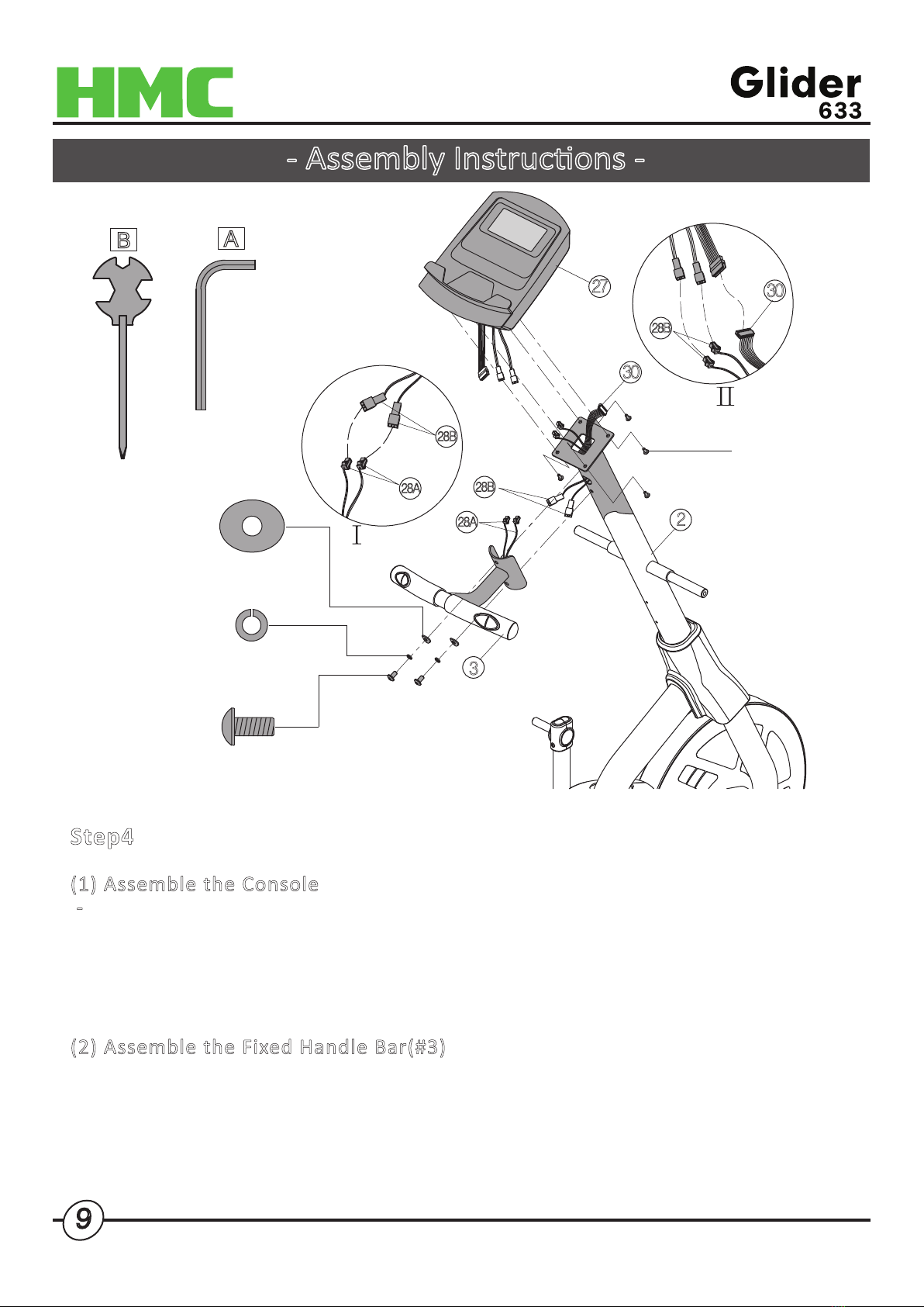
Step4: Assemble the Console(#27) and Fixed Handle Bar(#3)
(1) Assemble the Console
- Remove the Screws(#115-4pcs) from the back of the Console(#27).
- Connect the Cable of Console to the Cable(#30) inside the Up Right Tube(#2)
- Connect the Heart Rate Wire(#28B) to the Console(#27)
- Assemble the Console(#27) to the Up Right Tube(#2), ghten back the
screws(#115-4pcs).
(2) Assemble the Fixed Handle Bar(#3)
- Remove the Hex Socket Head Bolt(#79-2 sets) pre-assembled on the Up Right Tube(#2).
- Connect the Heart Rate Cable(#28A+#28B)
- Assemble the Fixed Handle Bar(#3) onto the Upright Tube(#2),ghten with the
Hex Socket Head Bolt(#79) sets.
#79 x 6pcs
Hex Socket Head Bolt
M8x20mml
#115 x 4pcs
Screw
M5x12mml
#102 x 6pcs
Curved Washer
8x21x2T
#103 x 6pcs
Spring Washer
A
B

- Assembly Instrucons -
10
4L
5L
#82 x 2pcs
Hex Socket Head Bolt
M8x42mml #110 x 2pcs
Nut M8
Step5: Assemble the Upper and Lower Swing Bar.
- Remove Hex Socket Head Bolt(#82) & Nut(#110), 2sets.
- Connect the Upper Swing Bar-L(#4L) to Lower Swing Bar-L(#5L), place the Hex
Socket Head Bolt(#82)&Nut(#110) onto the joint.
- Repeat the steps to the Right side.
C
A
Noce!!! Do Not Tighten the Screws Unl the Equpiment is Fully assembled.
11
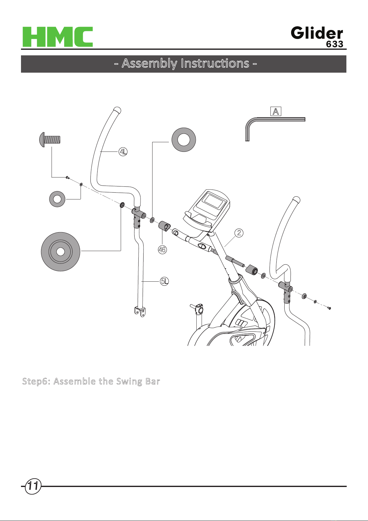
Step6: Assemble the Swing Bar
- Remove the Hex Socket Head Bolt(#80)、Washer(#93)、Washer(#98)& Axle Side
Cover(#61),2PCS each.
- Assemble the Swing Axle Cover(#46),Washer(#98),Swing Bar(#4+#5),Axle
Side Cover(#61) onto the Up Right Tube(#2),as shown in Figure.
- Fix it with Hex Socket Head Bolt(#80) & Washer(#93), do not over ghten
the screws.
#80 x 2pcs
Hex Socket Head Bolt
M8x18mml
#93 x 2pcs
Washer 8x21x2T
#98 x 2pcs
Washer 19.5x38x2T
46
2
5L
4L
A
#61 x 2pcs
Axle Side Cover
- Assembly Instrucons -
Noce!!! Please idenfy the L&R Parts before assembling.
12
#85 x 2pcs
Cup Head Bolt
M6x20mml
#94 x 4pcs
Washer 6x14x1T
#109 x 4pcs
Nut M6
6L
49L
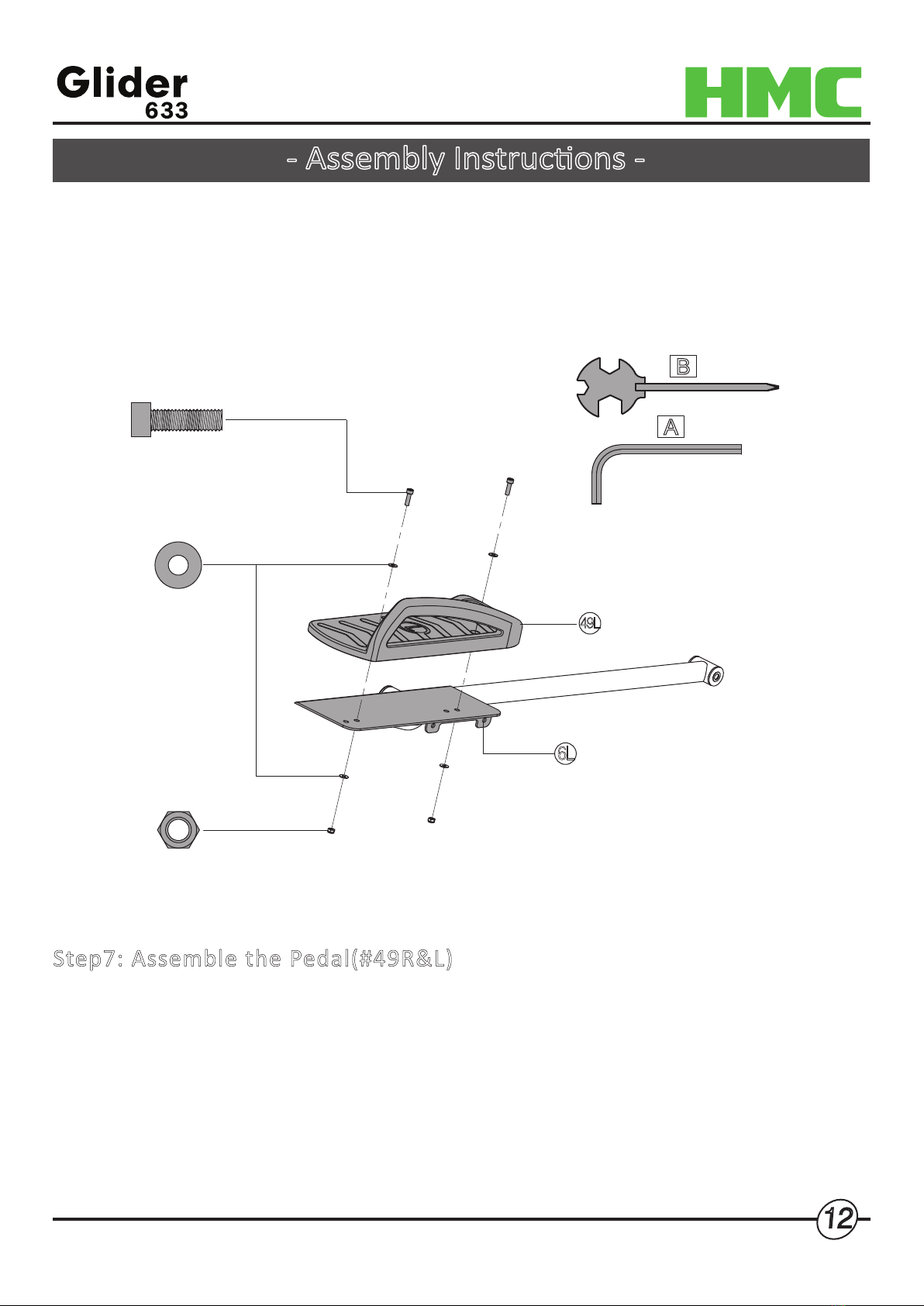
Step7: Assemble the Pedal(#49R&L)
- Remove the Cup Head Bolt M6x20mml(#85)x2pcs,Washer(#94)x4pcs &
Nut(#109)x2pcs from the Tool Kits.
- Place the Pedal(#49L) onto the Pedal Tube-L(#6L), fix it with Cup Head Bolt(#85),
Washer(#94) & Nut(#109).
- Repeat the steps to the Right side.
A
B
- Assembly Instrucons -
Noce!!! Please idenfy the L&R parts before assembling.
Noce!!! There are 2 holes on the Pedal Tube(#6 L&R), you can adjust the
training posion forward or backward.

13
7R
7L
#80 x 2pcs
Hex Socket Head Bolt
M8x18mml
#118 x 2pcs
Wave Washer
16.2x25x0.5T
#93 x 2pcs
Washer
8x21x2T
Step8: AssembleThe Wheel Tube
- Remove Hex Socket Head Bolt(#80),Washer(#93),Wave Washer(#118),Washer(#119)
& Axle
Side Cover(#61) from the Tool Kits, 2pcs each.
- Assemble the Wheel Tube(#7) onto the Main Frame(#1), Tighten with the
screws you just removed from the tool kits.
1
A
#61 x 2pcs
Axle Side Cover
#119 x 2pcs
Washer
8x38x2T

14
#80 x 2pcs
Hex Socket Head Bolt
M8x18mml
#77 x 4pcs
Hex Socket Head Bolt
M8x12mml
12
6L
6R
12
59
59 20
20
#96 x 2pcs
Washer 8x25x2T
#80 x 2cs
Hex Socket Head Bolt
M8x18mml
#96 x 2pcs
Washer
8x25x2T
#100 x 2pcs
Wave Washer
19x23x0.2T
Step 9: Assemble the Pedal Tube(6R&L)
- Remove the pre-assembled Hex Socket Head Bolt(#77-4PCS),then Remove the
End Cap(#59x2PCS).
- Remove the Hex Socket Head Bolt(#80x4PCS),Washer(#96x4PCS) & Wave Wahser
(#100x2PCS) from the Tool Kits.
- Connect the Pedal Tube(#6R&L) to Wheel Tube(7R&L) with Pedal Tube Axle(#20)
,then ghten back the screws as shown in Figure.
7R
7L
A
- Assembly Instrucons -
Noce!!! Do Not Tighten the Screws Unl the Equpiment is Fully assembled.

15
Step10: Connect the Pedal Tube(6R&L) to the Lower Swing Bar(5R&L)
- Remove the Hex Socket Head Bolt(#84),Washer(#97) & Nut(#111) from the Tool
Kits, 2 pcs each.
- Connect the Pedal Tube(6R&L) to the Lower Swing Bar(5R&L), ghten with the
bolt sets, as shown in figure.
- Please ghten up all the Screws and Bolts of Step 3/6/8/9/10.
5R
#84 x 2cs
Hex Socket Head Bolt
M10x68mml
#97 x 2cs
Washer 10x19x1.5T
#111 x 2cs
Nut M10
6R
5L
6L
A
B
- Assembly Instrucons -
Noce!!! Do Not Tighten the Screws Unl the Equpiment is Fully assembled.

16
Step11: Assemble the Joint Cover
- Remove the Screws(#90x2PCS) from the Tool
Kits.
- Place the cover(43A&B) on the joint and fix it
with the screws, as shown in Figure.
43B
43A
#90 x 2cs
Self-Tapping Screw
M4.5x15mml
43A
43B
B
- Assembly Instrucons -
40A
40B
40A
40B
#90 x 4cs
Self-Tapping Screw
M4.5x15mml
Step12:
Assemble the Swing Bar Cover(40A/B)
- Remove the Screws(#90x4PCS) from the
Tool Kits.
- Place the cover(40A&B) on the joint and
fix it with the screws,
as shown in Figure.

17
Step 13 : Assemble the Bole Holder(#71)
- Remove the pre-assembled Screw(#92-2pcs)
on the Up Right Tube(#2)
- Assemble the Bole Holder on the
Up Right Tube with the Screw.
#92 x 2cs
Screw
M5x20mml
71
2
B
Step 14:
Connect the Adopter(#35)
- As show in Figure.
35
1
- Assembly Instrucons -

- Console Instrucons -
To start or stop workout,
In stop mode,Press and hold for 3 seconds
to reboot the computer and reset all values to 0
Buon Funcons
18
START/STOP(ST/SP):
UP/DOWN:
ENTER:
RECOVERY:
To sellect Training programes , adjust funcon
value and Increase/Decrease workout level.
Confirm seng or selecon.
To Test Heart Rate Recovery level
The fitness ranking
F1.0 – excellent fitness
F2.0 – good fitness
F3.0 – sasfactory fitness
F4.0 – minimal fitness
F5.0 – fitness needs improvement
F6.0 – fitness needs major improvement
Mode:
Press to switch display form RPM to SPEED, ODO to
DIST , WATT to Calories during workout.
Press the Recovery, then hold-on the Heart
Rate Sensor for 1:00 Minute.

P1(Program 1) Manual
P2 Malibu P3 Quiet Trail P4 Through Town P5 Rolling Hills
P6 Yellow Stone P7 Uphill Battle P8 Everest P9 Easy Burn
P10 King Of The Hill P11 Hurdles P12 Grand Canyon P13 Waves
P14 Stairs P15 Cliffs P16 Giza P17 City Run
P18 Bumps P19 Pulse P20 High Hurdles P21 Ironman
Programes
19
- Console Instrucons -
Aer connecng the power, press + or - to sellect desired workout programe
from 21 preset programes.
Press ENTER to confirm selecon, then set up Time, Distance, Calories target,
press ST/SP to start workout.
If one of your seng target is completed, there will a beep sound and programe
will stop automacally, if you are willing to complete all the set up target, please
press ST/SP buon to connure the unfinished workout target.
Table of contents
Popular Fitness Equipment manuals by other brands

BH
BH Tecnovita ACTIVEPOWER YV16 Instructions for assembly and use

Precor
Precor move beyond S3.45 Assembly and maintenance guide

Lifeline
Lifeline PRO HALF RACK C1 owner's manual
ICON Health & Fitness
ICON Health & Fitness PRO-FORM CARBON STRENGTH FLAT BENCH user manual

Hudora
Hudora 76754 INSTRUCTIONS ON ASSEMBLY AND USE

Domyos
Domyos DS 910 manual


