HMP PDGpro User manual

www.humboldtmfg.com • 1.800.544.7220WW

CONTENTS
Service +49(0)391 2514666 05/2017 Instruction Manual HMP P Gpro – en
1
General Information
Safety instructions ................................................................................ 2
Information for Users 2
Symbols Used 2
Legal terms of reference 2
Intended Use ........................................................................................ 3
Plate Load Tester
General structure / Components ......................................................... 4
Specification ......................................................................................... 5
Measuring Instrument HMP PDGpro ..................................................... 7
Operation 7
Power Supply 9
Measuring
Prepare Measurements ...................................................................... 11
Install Loading mechanism 11
Installation of Measuring Frame (refer to Annex 1) 11
Connect evices 11
Measuring Procedure ......................................................................... 12
Start Measurement 12
Quit Measurement 13
Error Menus 14
Evaluation
Reading / Printing Measured ata ..................................................... 15
Export the Stored Measured ata ..................................................... 15
ata Transfer Measuring Instrument → USB Stick 15
ata Transfer Measuring Instrument → PC 16
elete Measuring Results .................................................................. 16
General ............................................................................................... 17
Settings
isplay ................................................................................................ 17
evice ................................................................................................. 18
Printer ................................................................................................. 18
Service ................................................................................................ 18
Calibration Menu ................................................................................ 18
Maintenance Menu ............................................................................. 18
Options
Thermal printer AP1300 ...................................................................... 19
Maintenance
Calibration .......................................................................................... 22
Hotline ................................................................................................ 22
Annex 1
Plate Load Tester spare parts ............................................................ 23
Annex 2
Operating Instructions Hydraulic System .......................................... 24
Annex
eclaration of Conformity

GENERAL INFORMATION
05/2017 Instruction Manual HMP P Gpro – en
2
Safety instructions
Information for Users
This instruction manual was prepared such that users can easily
become familiar with the HMP P G Plate Load Tester, and make use of
the tester for intended applications.
Users should carefully read this instruction manual and the safety
instructions prior to using the Plate Load Tester.
Users also have to read carefully the operating instructions by company
LUKAS for hand pump, hydraulic cylinder and quick coupler before
using the Plate Load Tester. These can be found on supplied C .
Follow the instructions of this instruction manual and the operating
instructions of company LUKAS without exception.
Symbols Used
Warnings and instructions are highlighted as described below:
Warning
This symbol is used in conjunction with related text to draw
user's attention to hazards and risks which may cause failure of
tester components or adversely affect operating procedures, in
case users do not take the corresponding precautions.
Note
This symbol and the related text identify technical requirements
and provide additional information to be taken into account by
the operator to carry out the following operations effectively
and safely.
Legal terms of reference
The Plate Load Tester complies with the current state of the art and all
applicable safety regulations.
Construction and function of the Plate Load Tester meet the
requirements laid down in IN 18134, issue 2012 »Soil – Testing
procedures and testing equipment – Plate load test«.
The Plate Load Tester meets the basic safety requirements laid down in
the EU irectives for Harmonisation referenced in the EU eclaration of
Conformity.

GENERAL INFORMATION
05/2017 Instruction Manual HMP P Gpro – en
3
Intended Use
The Plate Load Tester is exclusively intended for determining the soil
bearing capacity and the compaction quality of the soil referred to
IN 18134, issue 2012 »Soil – Testing procedures and testing equip-
ment – Plate load test«.
Its intended use also includes:
❙Compliance with the safety instructions and safety regulations con-
tained in this instruction manual and in the operating instructions from
company LUKAS for the hydraulic components (on supplied C ).
❙Compliance with the maintenance and servicing instructions con-
tained in this instruction manual and in the operating instructions from
company LUKAS for the hydraulic components (on supplied C ).
Any other use or any use beyond this definition is not intended and may
cause injury to people and damage to property.
The manufacturer/supplier shall not be held liable for damages resulting
from other than the intended use. The risk shall be borne solely by the
user.

PLATE LOAD TESTER
05/2017 Instruction Manual HMP P Gpro – en
4
General structure / Components
Loading mechanism and Load plate
Figure 1 (refer to Annex 1)
1 Ball-and-socket joint with magnetic holder
2 Extension pieces
3 Hydraulic cylinder
4 Thrust piece
5 Load cell
6 Measuring tunnel
7 Load plate with bubble level
8 Hydraulic pump
Settlement measuring mechanism (measuring frame)
Figure 2
1 Extension arm with measuring finger
2 Traverse
3 Measuring frame
4 Measuring head
5 ial gauge
6 Bubble level
Electronic dial gauge
Figure 3
1 ial gauge
2 ial gauge cable
➄
➁
➃
➅
➂
➀
➁
➀
➀
➁
➃
➂
➆
➄
➅
➇
Figure
1
Figure
2
Figure
3

PLATE LOAD TESTER
05/2017 Instruction Manual HMP P Gpro – en
5
Measuring case
Figure 4
1 Measuring instrument
2 Measuring head
3 Thrust piece
4 Electronic dial gauge
5 Electrical load cell
6 Printer (optional)
Measuring instrument
Figure 5
1 TFT colour display
2 Measuring cable
3 Ambient Light Photo Sensor
4 USB port
5 Printer port
6 Function keys
Specification
Loading mechanism
Hydraulic pump with 100 kN cylinder
and 150 mm lift with high-pressure hose of 2 m in length.
1 set of hydraulic cylinder extension pieces (plug-type connection)
1 pressure plate with magnetic holder and upper ball-and-socket joint
Load plate
with adjustable bubble level
iameter 300 mm
Thickness of plate 25 mm
Settlement measuring mechanism (measuring frame)
Support frame on three-point bearing, equipped with insertable and
turnable contact element ( IN 18134, Fig. 3a) and adjustable feet
imensions:
Length 2,320 mm
Width 570 mm
Height 420 mm
Weight 13.2 kg
2
4
6
1
5
6
2
3
4
5
1
Figure
4
Figure
5

PLATE LOAD TESTER
05/2017 Instruction Manual HMP P Gpro – en
6
Measuring of load
❙Electrical load cell 50 kN or 100 kN,
complete with thrust piece and adapter
Measuring of settlement
❙Electronic dial gauge
25 mm measuring range, 0.01 mm resolution,
local display unit, IP 42
Automatic evaluation unit
❙Measuring head
logging load and settlement data, interfering-immune digital trans-
mission to measuring instrument
❙Measuring instrument
data logger for load and settlement data with automatic processing
and evaluation facilities as well as storage capability for more than
200 tests
- Comfortable user interface
- 3.5“ TFT colour display
- Rechargeable Lithium-ion polymer battery pack (Lithium polymer
battery pack)
- Interfaces: Bluetooth, USB, thermal printer
- GPS integrated
❙thermal printer to print data and pressure settling lines on the site
(optional)
❙Aluminium case for measuring instruments
imensions: 460 x 350 x 210 mm
Weight: 8 kg (with load cell 50 kN) or.
10.5 kg (with load cell 100 kN)

PLATE LOAD TESTER
05/2017 Instruction Manual HMP P Gpro – en
7
Measuring Instrument HMP PDGpro
Operation
The measuring instrument HMP PDGpro can be operated easily and
intuitively by means of the function keys.
Key functions
Switch on / off measuring instrument
Select upward
Select downward
Select to the left / Scroll
Select to the right / Scroll
Confirm selection / Start action
Buttons/Symbols
The currently active button is displayed with colour, the inactive buttons
are grey.
Main menu
Measuring page 11
Measured data page 15
(… read, print, export, delete)
Settings / Service page 17.
(display, device, printer, support, calibration)
General
Back to the previous menu
iscard frozen measuring values, approach set point again
Scroll (test series/measured data)
Store
elete
Print test series
Export test series page 15
a

PLATE LOAD TESTER
05/2017 Instruction Manual HMP P Gpro – en
8
Display
In the main menu the display is subdivided into status line and button
area (Figure 6).
In the submenus the display is subdivided into status line, button area/
indicating area and footer (Figure 7). With the keys can be
switched between button area/indicating area and footer.
The information on the left of status line will be changed according to
several menus. In the main menu (Figure 6) type and number of device
are displayed for example.
The information on the right side of status line is the same in all menus:
Status Bluetooth
displaying in status line, in case Bluetooth is active
(during data transfer only)
Status GPS
displaying in status line, in case GPS is active and available
State of charge of the printer
displaying in status line, in case printer is connected
State of charge of the measuring instrument
Overview Menu Functions
Measuring Taking measurement
y
Measured data Show single measurements Print B
Export Q
Export Q
elete (all measurements) D
Settings isplay K ate
Time
Language
evice X Plate diameter
GPS
Unit
Calibration
Printer B Head datea
ate/time
Graphics
Service L
Calibration menu M
Maintenance R
By confirming the button G you always come back to the previous
menu.
Figure
6
Figure
7

PLATE LOAD TESTER
05/2017 Instruction Manual HMP P Gpro – en
9
Power Supply
The measuring instrument HMP PDGpro is powered by a rechargeable
Lithium-ion polymer battery pack (abbreviated herein-after as Lithium
polymer battery pack) which is provided with overcharge protection and
deep discharge protection.
Safety
❙Do not dismantle, open or shred Lithium polymer battery
pack. Exposure to the ingredients contained within or their
ingredients products could be harmful.
❙Do not expose Lithium polymer battery pack to heat or fire.
Avoid storage of device/battery pack in direct sunlight.
❙Lithium polymer battery pack must not be short-circuited.
❙Do not subject Lithium polymer battery pack to mechanical
shock.
❙Observe local, state and federal laws and regulations for
disposal.
❙The supplied accessories must only be used for devices
supplied by HMP and according to this instruction manual.
Any other use may cause damages.
Switching-off automatically
The measuring instrument HMP PDGpro switches off automatically, in
case there is no action for about 90 s.
The device will not switch off automatically, as long as it is in
the measuring mode.
If the Lithium polymer battery pack of the measuring instrument drops
below the voltage required for operation, the device switches off
automatically, in order to prevent a deep discharging of the battery
pack. Before switching on the instrument again, please charge the
battery pack.
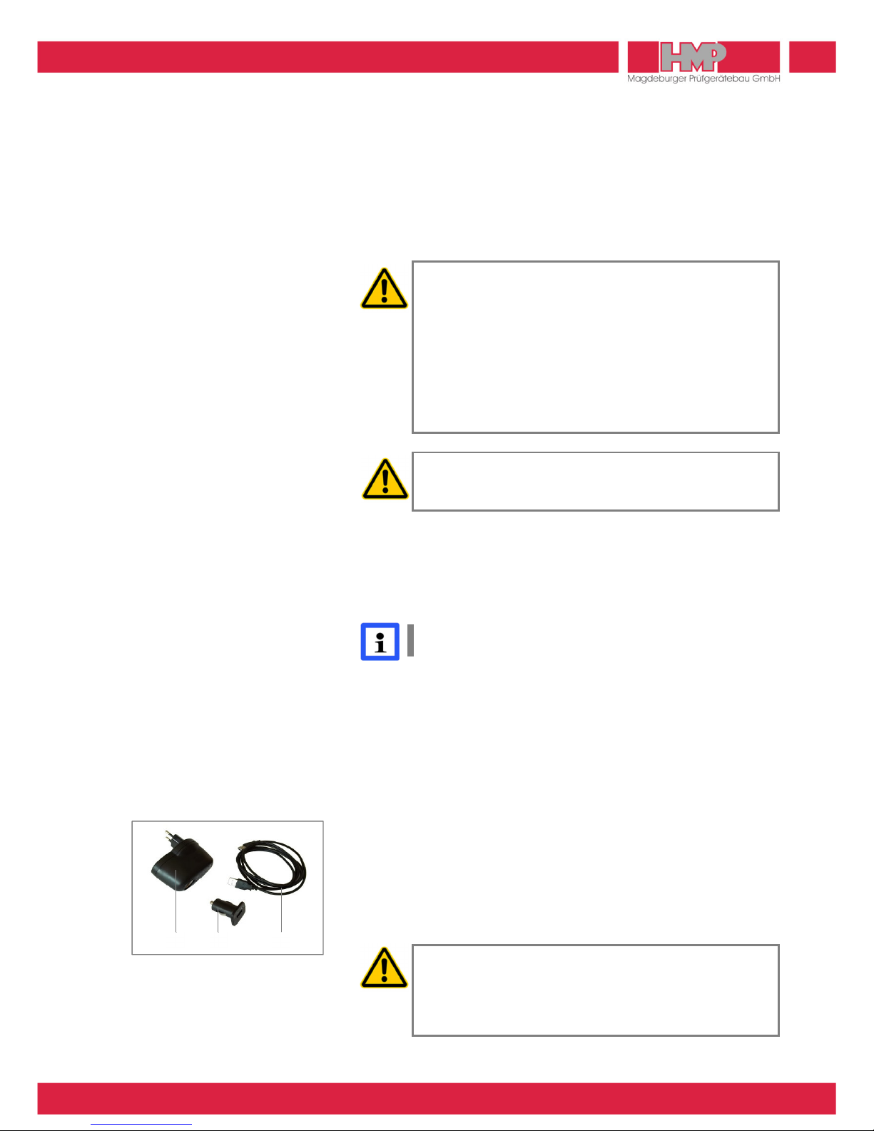
Charging of Lithium polymer battery pack
Lithium polymer battery pack should be charged only by means of the
supplied accessories (Figure 8). Accessories for charging the battery
pack – USB cable (1), USB car charger (2) and AC/ C adapter (3) – are
placed in the carrying case.
The USB car charger can be connected with a car-battery 12 V or by
means of AC/ C adapter to mains 230 V / 50 Hz.
❙For charging Lithium polymer battery pack only the supplied
chargers, which are provided for use with this device, should
be used.
❙Lithium polymer battery pack should not be charged over a
longer period if it is not needed.
2
1
3
Figure
8

PLATE LOAD TESTER
05/2017 Instruction Manual HMP P Gpro – en
10
Lithium polymer battery pack of measuring instrument should be
charged before first use and in case that state of charge is 15% or
lower.
Lithium polymer battery pack should be charged at the latest
when the note on the left (Figure 9) appears on the screen of
measuring instrument.
■Switch off measuring instrument and connect it with the USB car
charger via USB cable.
■Connect the USB car charger to a car socket 12 V or via AC/ C
adapter to mains supply 230 V / 50 Hz.
■isconnect the charger from mains supply when charging of Lithium
polymer battery pack has been finished.
It is not possible to overload the Lithium polymer battery pack, since it is
equipped with an overload protection. When the battery pack is fully
charged, the charging current entry is automatically interrupted.
The Lithium polymer battery pack will only be charged, in case
that the measuring instrument is switched off.
Figure
9

MEASURING
05/2017 Instruction Manual HMP P Gpro – en
11
Prepare Measurements
Install Loading mechanism
■Prepare the test site in compliance with the requirements of
IN 18 134, issue 2012.
■Place the load plate on the test site.
The opening of the measuring tunnel points into the direction from
which the measuring finger of the measuring frame is inserted.
■Mount the load cell onto the pin of the load plate and the thrust piece
onto the load cell.
■Attach the hydraulic cylinder to the pin of the thrust piece.
■Mount the ball-and-socket joint with magnetic holder to the loading
vehicle.
■Use the extension pieces to adjust height differences.
Installation of Measuring Frame (refer to Annex 1)
■Mount the traverse (2) to the longitudinal beam of the measuring
frame (3) and align with height adjustment (star grips).
■Remove the extension arm (1) from the bracket, insert it into the
measuring frame and fix it by means of the 2 star grips.
■Insert the measuring finger into the measuring tunnel until the relevant
mark is reached, and align horizontally by using the circular bubble.
■Place the dial gauge in the dial gauge bracket of the measuring frame
and make settings it as appropriate (set to zero).
Connect Devices
Position measuring head
■Mount the measuring head to the traverse (magnetic fixture).
Connect the load cell
■Connect the load cell cable to the measuring head outlet labeled
»Force«.
Connect the dial gauge (used for distance measuring)
■Connect the dial gauge cable to the dial gauge.
■Connect the dial gauge cable to the measuring head outlet labeled
» istance«.
Connect measuring instrument
■Connect the cable of measuring instrument to the measuring head.

MEASURING
05/2017 Instruction Manual HMP P Gpro – en
12
Measuring Procedure
For theoretical foundations of the measuring process please refer to
IN 18134, issue 2012.
Start Measurement
■Press the key to switch on the measuring instrument.
evice will be powered up and GPS starts.
The main menu (Figure 10) appears on the screen with type &
number of device (xxxxx) and state of charge of the measuring
instrument in status line as well as the several menu buttons in
main area of display.
Button »Measured data« is active until GPS data are determined.
Then button »Measuring« will be activated (Figure 11) and »GPS« is
displayed in status line.
GPS data are only available and they will only be stored with
the test series, in case »GPS« is displayed in status line.
In case that measurement shall be carried out without recording the
GPS data, then in the menu settings/device Z has to be chosen for
GPS ( page 18). Immediately after starting device the button
»Measuring« is active and the measuring process can begin.
Before starting the measurement the desired measuring range
(plate diameter) has to be chosen within the measuring
instrument ( page 18).
■Confirm the button »Measuring« (Figure 11) by pressing the key.
The menu »Measuring« (Figure 12) is displayed on the screen:
Number of the current measuring series and the current measuring
range (plate diameter) (xxx-xxx)
Compression (σ) #.#### MN/m²
Settlement (s) #.## mm
These values result from weight of testing equipment.
Measuring is not possible in case of full memory. A
corresponding note appears.
Value 1
■Acknowledge button »0,00« by pressing the key to tare the
displayed values.
The values 0.0000 MN/m² for compression and 0.00 mm for
settlement appear on the display. By that offset values, if any, are
cleared.
Set value and MP01 for 1st measuring point are displayed.
Figure
10
Figure 11
Figure
12

MEASURING
05/2017 Instruction Manual HMP P Gpro – en
13
■Acknowledge Button »s=0« by pressing the key after approa-
ching the required preload, according to IN 18134, issue 2012, to
set the displayed value for the settlement to zero.
■The start value for the pressing and the zero value for the settlement
appear on display (Figure 14). The local display on the dial gauge
remains unaffected by this zero setting.
■By confirming button E these values are stored as first measured
values.
Please refer to DIN 18 1 4, issue 2012 for the required number
of measurements and set values to perform.
Set values according to DIN 18 1 4, issue 2012 are stored on
the measuring device as orientation for the examiner, for load
plates with diameter of 00 mm, 600 mm and 762 mm. The
specific set values are displayed on the screen during
measuring.
Perform Measurement
■Approach the set point with the hydraulic pump.
(Operating Instructions Hydraulic System refer to Annex 2, page 24.)
The measured values for compression and settlement appears on
the display (Figure 15).
The number of the current measuring series and the current
measuring range, the number of the current measuring point and
also the set value for the pressing are displayed.
■Accept the values after the required waiting time by pressing the
key.
The values are frozen in the display.
■Confirm button E by pressing the key to store the (frozen)
measuring values for the current measuring point (Figure 16).
The current measured values are displayed on the screen again
and the values for next measuring point can be captured.
In case the (frozen) values shall be discarded,
■select button a and confirm.
The current measured values are displayed on the screen again
and the values for the current measuring point can approached
new.
Follow the procedure described above for any further set values.
Quit Measurement
All required measurements completed, the measuring procedure can be
terminated.
■After storing of last measuring value select Button G and confirm with
key.
The menu shown on the left is displayed on the screen (Figure 17).
■In order to return to the last measuring value and to continue the
measurement select button Z and confirm.
■In order to quit the measurement select button J and confirm.
Figure
13
Figure
14
Figure
15
Figure
16
Figure
17

MEASURING
05/2017 Instruction Manual HMP P Gpro – en
14
■When query »Save measurement?« is displayed confirm button J
again.
Measuring series will be completed and stored, results will be
calculated.
The values of EV1, EV2 and the ratio EV2/EV1 are displayed on the
screen (Figure 18).
After completing one measuring series it is possible to print out the
current measuring series (only devices with printer) and also to display
the curve data (pressure settling lines), the GPS position and the
measured data.
In order to discard the complete measuring series,
■select button Z when query »Save measurement?« is displayed and
confirm.
Measuring series will not be stored. The main menu appears.
Error Menus
The measuring instrument provides instructions – to monitor the measu-
ring procedure – which pop up as an error report before measurement
or during the measurement.
The following error reports might appear before the measurement:
Error report Error cause
σc.error no connection between
measuring instrument
and measuring head
σerror no connection between load cell and m
easuring
head
s error no connection between dial gauge and measu-
ring head or dial gauge is not switched on
■Check/establish the connections.
■Continue measurement as soon as the connections are correct.
The following error reports might appear during the measurement:
Error report Error cause
σ0.0000 MN/m²
In case that the required minimum value for
compression is not reached according to
IN
18134, issue 2012, the value will be shown
in red.
■Confirm button a by pressing key.
■Approach the required value for compression and continue measure-
ment.
Figure
18

EVALUATION
05/2017 Instruction Manual HMP P Gpro – en
15
Reading / Printing Measured Data
The in the database stored test series and -results can be displayed via
button (Figure 19) on the screen and printed out if required (only
devices with printer).
When no data are stored in memory, the button is without
function.
Before using the thermal printerAP1 00 please read the
instruction manual ( page 19) and follow the instructions
regarding putting into operation and handling.
■Select and confirm the button in the main menu.
The stored test series appear on the screen (Figure 20).
By confirming the buttons M or N with more test series can be
displayed.
■Choose the middle indicating area by means of the keys, select
the desired test series by means of the keys and confirm by
pressing the key.
The results of the selected test series are displayed on the screen
(Figure 21).
By confirming the buttons M or N with the values of several mea-
suring points, GPS position and settlement curves (Figure 22) can be
displayed.
■Select button B and confirm with key.
ata of selected test series are printed.
GPS data will only be printed, in case GPS is enabled J in
menu Settings/Device and when GPS data are stored with the
selected measuring series.
Export the Stored Measured Data
The test series and –results stored in the database can be transferred
via USB interface to the supplied USB stick or to PC.
Data Transfer Measuring Instrument → USB Stick
■Connect the USB stick to the measuring instrument.
■Select within measuring instrument under menu measured data /
export Q the transfer mode P (Figure 23) and confirm with key.
The data are being copied to the USB stick.
After completion of data transfer the measuring instrument
switches off automatically.
To transfer the data from the USB stick to the PC see instruction manual
»Protocol software for the Plate Load Tester HMP PDGpro«.
Figure
19
Figure
20
Figure
21
Figure 22
Figure
23

EVALUATION
05/2017 Instruction Manual HMP P Gpro – en
16
Data Transfer Measuring Instrument → PC
■Connect measuring instrument and PC via the supplied USB cable.
■Select within measuring instrument under menu measured data /
export Q the transfer mode R (Figure 24) and confirm with key.
The measuring instrument works now just like removable media.
■After completion of data transfer switch off the measuring instrument
and disconnect measuring instrument from PC.
To transfer data from measuring instrument to PC see instruction
manual »Protocol software for the Plate Load Tester HMP PDGpro«.
Delete Measuring Results
The test series and –results stored in data base can be deleted via
Button D.
■Select and confirm the button in the main menu.
■Confirm button D by pressing the key (Figure 25).
The menu on the left is displayed on the screen (Figure 26).
■Select button D and confirm with key.
All measurements will be deleted.
The main menu is displayed on the screen.
Stored series cannot be deleted individually.
Figure
24
Figure
25
Figure
26

SETTINGS
05/2017 Instruction Manual HMP P Gpro – en
17
General
Via button F in the main menu you can reach the menu settings
(Figure 27), in which different display-, device- and printer settings can
be carried out.
All carried out settings are only saved, when returning to the
main menu. In case that the measuring instrument is switched
off before, all modifications get lost.
Display
In menu » isplay« K settings for date, time and language can be carried
out (Figure 28).
Set Date
■Select button » ate« and confirm with key.
■Change the day by means of the keys.
■Select the month by pressing the key.
■Change the month by means of the keys.
■Select the year by pressing the key.
■Change the year by means of the keys.
■Confirm the current date setting by pressing the key.
By pressing the key the menu »date« can be left at any time.
■Select Footer G by means of the or key and confirm with
key.
The menu »Settings« appears.
■Select Footer G by means of the or key and confirm with
key.
The set date will be saved and the main menu appears.
Set Time
■Select button »Time« and confirm with key.
■Change the minutes by means of the keys.
■Select the hours by pressing the or key.
■Change the hours by means of the keys.
■Confirm the current time setting by pressing the key.
By pressing the key the menu »Time« can be left at any time.
■Select Footer G by means of the or key and confirm with
key.
The menu »Settings« appears.
■Select Footer G by means of the or key and confirm with
key.
The set time will be saved and the main menu appears.
Figure
27
Figure
28

SETTINGS
05/2017 Instruction Manual HMP P Gpro – en
18
Select Language
■Press key so often until the desired language appears.
■Select Footer G by means of the or key and confirm with
key.
The menu »Settings« appears.
■Select Footer G by means of the or key and confirm with
key.
The set language will be saved and the main menu appears.
Device
In menu » evice« X the following settings can be carried out for device
configuration (Figure 29):
❙Plate diameter (300/600/762/Kraft) set measuring range
(∅ of load plate or force)
❙GPS (J / Z) activate / deactivate GPS
❙Einheit (MN/m² / MPa) set unit
❙Calib.date (J / Z) show / don’t show calibration
date on start screen
Printer
In menu »Printer« B the following settings can be carried out for printer
configuration (Figure 30):
❙Head data (J / Z) print out protocol head (always active)
❙ate/time (J / Z) print out date / time
❙Grafik (J / Z) print out curve
Service
In menu »Service« L various device information, which are relevant for
HMP service, are indicated.
Calibration Menu
The menu »Calibration« M is not available for users.
Maintenance Menu
The menu »Maintenance« R is not available for users.
Figure
29
Figure
30

OPTIONS
05/2017 Instruction Manual HMP P Gpro – en
19
Thermal printer AP1 00
Included in the HMP PDGpro scope of supply is a thermal printer AP
1300 (optional).
Power Supply
The printer can be operated independently from a power supply unit
and is powered by a 1.8 Ah NiMH power pack housed in the printer
(Figure 31). Thus, the printer can be carried from job to job.
Safety
❙The NiMH power pack is provided with an internal fuse unit.
However, a short-circuit may occur when the NiMH power
pack gets into contact with metallic items.
❙The power pack must not be opened; otherwise it may leak
out or a short-circuit may occur.
❙Before you remove or replace the power pack, disconnect it
from the external power pack charger.
The power pack has to be charged only by means of the supplied
power pack charger. The power pack charger can be connected with a
car-battery 12–24V or by means of an AC/ C adapter to mains
230 V / 50 Hz. The AC/ C adapter is included in the delivery contents of
measuring instrument HMP PDGpro. Charger and adapter are placed
in the carrying case.
The printer AP1300 is shipped with a connected and fully loaded power
pack.
❙When the printer is used for the first time after a lengthy
period or has been standing idle for a lengthy period,
recharge the power pack prior to use.
❙In the event of malfunction the printer may only be opened by
authorised personnel.
❙The supplied accessories must only be used for devices
supplied by HMP and according to this instruction manual.
Any other use may cause damages.
Charging of power pack
❙For Changing the power pack it is only allowed to use the
supplied power pack charger.
❙Fully charging the power pack takes 15 hours at most.
❙Use the power pack charger only indoors. Disconnect the
device from the mains if it is not used. Do not operate the
device in case of damage to the housing or the mains plug.
❙Only charge nickel/metal hydride power packs; use of the
charger for other batteries may cause an explosion hazard.
❙Do not open the power pack charger.
Figure
31
Table of contents
Popular Test Equipment manuals by other brands

Orbit Controls
Orbit Controls OC 3010 owner's manual

SIGLENT TECHNOLOGIES
SIGLENT TECHNOLOGIES SDS3000X HD Series quick start

PCB Piezotronics
PCB Piezotronics PCB-137B29B Installation and operating manual

iPA
iPA HEAVY RANGER MUTT 9102 Operator's manual

3M
3M 900AST Series instruction manual

Martindale Electric
Martindale Electric EZ365 instruction manual

Spinner
Spinner BN 533810 product manual

AEMC instruments
AEMC instruments 6418 user manual

Photon Systems Instruments
Photon Systems Instruments AquaPen-C AP 110-C Manual and user guide

sauter
sauter THM-N instruction manual

Neilsen
Neilsen CT2134 Original instruction

Dräger
Dräger Alcotest 6820 quick start guide