Nagas ABE Series User manual

Rev 1_2023
ABE SERIES
ENERGY RECOVERY SYSTEM
Indoor and Outdoor installation
INSTALLATION, OPERATION AND MAINTENANCE MANUAL
1385, Lionel-Boulet Blvd., Varennes, Québec J3X 1P7 • Toll Free: 1 888 514-8007 • Tel: 438 338-1101 • www.nagasinnovation.com

2 of 45
Installation, operation, and maintenance manual-ABE Rev 1_2023
CAUTION!
This instruction manual should be kept with the device and kept legible.
Hazard and risk identification is the first step in risk assessment, please read carefully:
DANGER ! Indicates a situation of imminent risk that, if not avoided, will result in death or
serious injury.
WARNING ! Indicates a potentially risky situation that, if not avoided, could result in death or
serious injury.
CAUTION ! Indicates a potentially risky situation that, if not avoided, can result in bodily
injury or property damage.
NOTICE ! Indicates special instructions for installation, operation or maintenance that are
important but are not related to bodily injury or property damage.
Before you begin installing the device, read, understand, and follow all the instructions given in this
manual, including all safety precautions and warnings.
This device is connected to high voltages and contains parts that can move unexpectedly.
Never open the access doors to the device while it is running.
The unit must be securely and properly grounded.
An electric shock, serious injury or death could occur if the instructions given in this manual are not
followed.
Always unplug and lock the power supply before maintaining this equipment. All work must be done
by a qualified technician.
DO NOT BYPASS LOCK OR SAFETY SWITCHES UNDER ANY CIRCUMSTANCES.

3 of 45
Installation, operation, and maintenance manual-ABE Rev 1_2023
SUMMARY
Table des matières
1. CODE AND REGULATION ......................................................................................................................................... 4
2. GENERAL INFORMATION ......................................................................................................................................... 5
2.1. INTRODUCTION....................................................................................................................................................... 5
2.2. RESPONSIBILITIES ................................................................................................................................................... 5
2.3. RECEPTION AND STORAGE ..................................................................................................................................... 5
2.4. LIMITED GENERAL WARRANTY ............................................................................................................................... 6
2.5. PARTS, REPAIRS AND MAINTENANCE .................................................................................................................... 7
3. INSTALLATION INSTRUCTIONS ................................................................................................................................. 8
3.1. GENERAL ................................................................................................................................................................. 8
3.2. UNPACKING ............................................................................................................................................................ 8
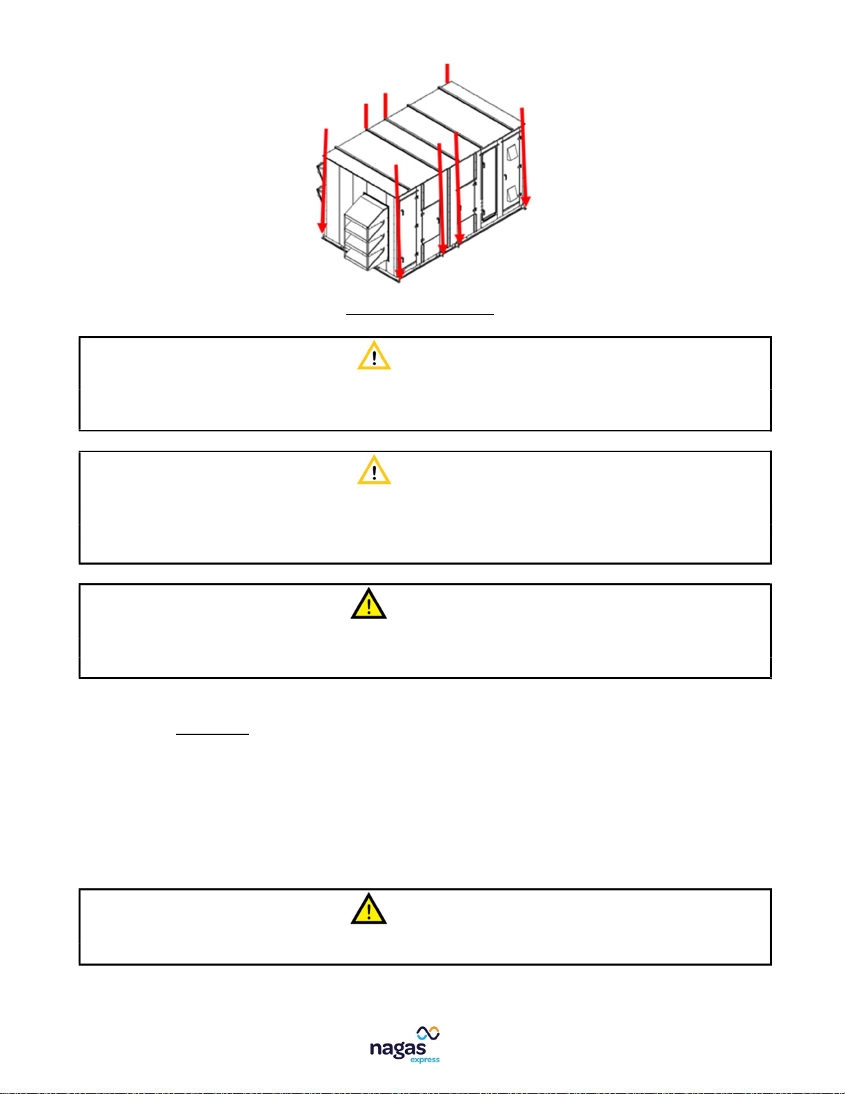
3.3. LIFTING .................................................................................................................................................................... 8
3.4. ASSEMBLY ............................................................................................................................................................... 9
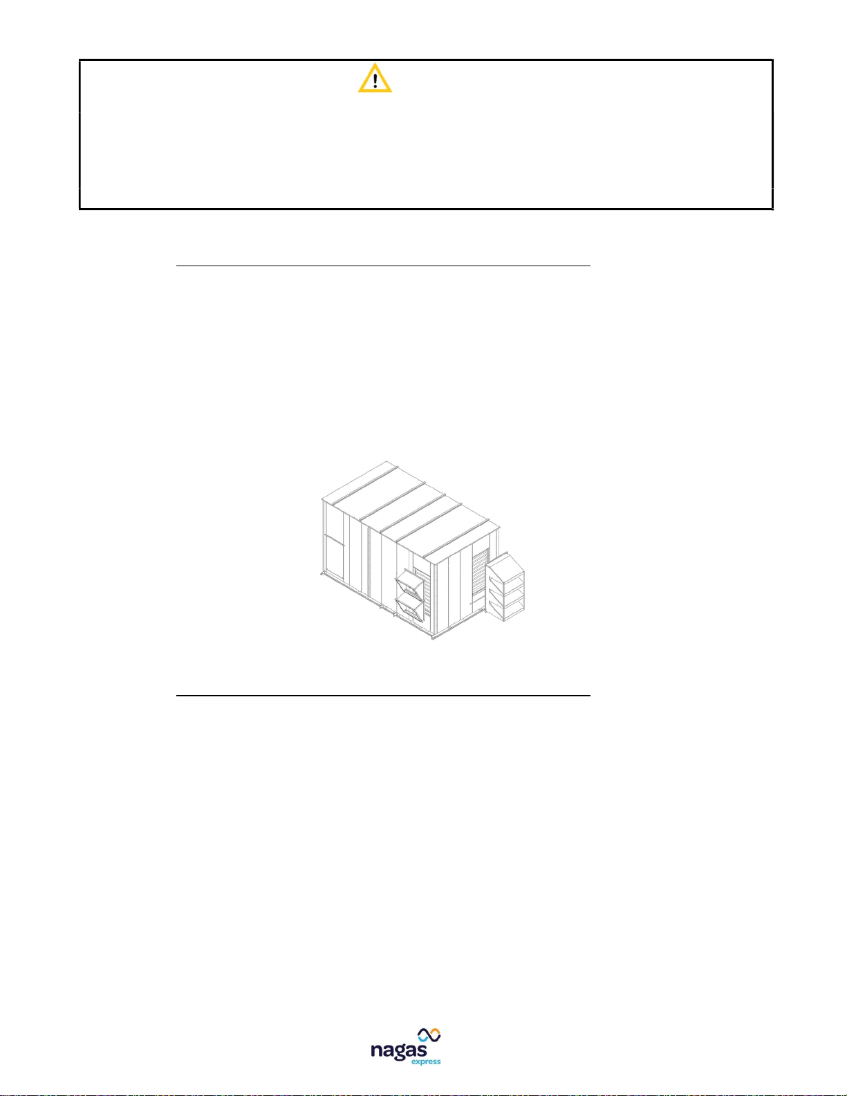
3.5. INSTALLATION OF AIR INLET/OUTLET COVERS (IF REQUIRED) ........................................................................... 10
3.6. INSTALLATION OF AIR INLET/OUTLET COVERS (IF REQUIRED) ........................................................................... 10
4. START-UP INSTRUCTIONS ...................................................................................................................................... 12
5. SHUTTING DOWN THE UNIT .................................................................................................................................. 13
5.1. EXTENDED SHUTDOWN ........................................................................................................................................ 13
5.2. EMERGENCY SHUTDOWN ..................................................................................................................................... 13
6. PRINCIPLE OF OPERATION OF THE RECUPERATOR ................................................................................................. 14
6.1. DESCRIPTION OF THE RECOVERY UNIT HOUSING ................................................................................................ 15
7. SEQUENCE CONTROL ............................................................................................................................................. 16
7.1. LOCAL CONTROL MODE ........................................................................................................................................ 16
7.2. REMOTE CONTROL MODE .................................................................................................................................... 16
7.3. BACNET CONTROL MODE ..................................................................................................................................... 17
7.4. CONTROL OF THE RECUPERATION ........................................................................................................................ 18
8. CONTROL INTERFACE HMI ..................................................................................................................................... 20
8.1. NAVIGATION IN THE HUMAN MACHINE INTERFACE (HMI) ................................................................................. 20
8.1.1. HMI STRUCTURE........................................................................................................................................... 21
8.1.2. BACNET LIST ................................................................................................................................................. 30
8.1.3. ALARMS LIST ................................................................................................................................................ 32
9. TYPICAL WIRING DIAGRAM ................................................................................................................................... 34
9.1. TYPICAL WIRING DIAGRAM .................................................................................................................................. 34
9.2. TYPICAL CONTROL PANEL ..................................................................................................................................... 40
10. UNIT MAINTENANCE ......................................................................................................................................... 41
11. BLOWERS BALANCING PROCEDURE .................................................................................................................. 43
12. STARTUP REPORT .............................................................................................................................................. 44
NOTICE: The specifications, illustrations and description in this document were, to the best of our knowledge,
accurate at the time they were approved for printing. Nagas Innovation Inc. has a policy of continuous
product improvement and reserves the right to change design and specifications, discontinue offering certain
features, or discontinue production of a given model size without notice. For more information, please
contact your local representative and your authorized distributor.

4 of 45
Installation, operation, and maintenance manual-ABE Rev 1_2023
1. CODE AND REGULATION
This product is intended to be installed, indoors or outdoors depending on the model, by a qualified installer for
this type of device. This recovery unit is designed for industrial or commercial use only. The must comply with
the latest laws, regulations, and electrical code CSA C22.1/NFPA 70. All electrical installations must conform to
the electrical diagrams of the unit.
Electrical and airflow requirements are described on the nameplate affixed to the unit. Following these
requirements is mandatory for safe use and performance of the unit.
CAUTION!
CLEARANCES TO COMBUSTIBLE MATERIAL
A minimum clearance of 1 inch is required between the walls of the appliance and any combustible material.
A minimum clearance of 39 inches is required in front of the appliance door to access the controls. Allow
sufficient space around the unit for servicing and around the air intake hood to prevent snow accumulation.
Clearances to combustible materials and
controls access
Position Inch [mm]
Wall of the controls 39 [1000]
Contour walls
1 [25]
Floor
None
WARNING!
- Installation, modification, adjustment, or poor maintenance can cause property damage, injury, or death.
Read the installation, start-up and maintenance instructions carefully before installing, using, or repairing
the device.
- The instructions below show the recommended installation and use that we have tested and believe to
be safe. If the installer decides not to follow these instructions, it will be the installer's responsibility to
test and validate the security and functionality.

5 of 45
Installation, operation, and maintenance manual-ABE Rev 1_2023
2. GENERAL INFORMATION
2.1. INTRODUCTION
This manual has been produced to simplify the installation, maintenance, and operation of this equipment. Strict
application of these instructions will ensure that the installation complies with the manufacturer's
recommendations.
The application of the instructions given in this manual is one of the conditions of the warranty, but it does not
guarantee at any time compliance with the applicable laws, rules, codes, and regulations of the country of
destination of the installed equipment.
This manual is protected by international copyright laws. No part of this manual may be reproduced,
distributed, translated, or transmitted in any form or by any means, electronic or mechanical, including
photocopying, recording, or recording in an information retrieval and archiving system, without the prior
written permission of the manufacturer.
2.2. RESPONSIBILITIES
This equipment must be used specifically for the purposes for which it was designed and manufactured. Any
contractual liability of Nagas Express is therefore excluded in the event of injury to persons, animals, or damage
to the goods, resulting from errors in installation, adjustment, maintenance, or improper use.
Nagas Express is responsible for the compliance of the device with the codes and construction standards in force
at the time of sale. Knowledge of and compliance with the legal provisions as well as the standards inherent in
the design, implantation, installation, commissioning, or maintenance are the sole responsibility of the installer
or integrator.
Be aware that this manual does not cover all possibilities, situations, or contingencies. Regular service is required
to ensure the proper functioning and safety of this equipment. If you have any doubts about the performance
of these tasks yourself, you need to hire a qualified specialist. Negligence in maintenance may cause equipment
failure, property damage and/or damage to building occupants and will void the equipment warranty.
2.3. RECEPTION AND STORAGE
Upon receipt of the equipment, check that the packaging and contents have not been damaged during shipping.
Inspect the packaging for punctures or other signs of damage. Remove the packaging and check if there is no
external damage to the unit.
All units that leave our factory are tested and carefully inspected immediately prior to shipment to ensure they
are in good working order at that time. Check the packing slip to ensure that all parts for field installation have
been received. If damage is found or parts are missing, please contact your local authorized distributor or
representative.
If equipment must be stored before being installed on site, you should observe the following precautions:
Store in a well-drained, dry area that will not accumulate surface water to avoid damage from moisture in
wet soil, dew or rain.
Do not store in a location where equipment could be physically damaged.

6 of 45
Installation, operation, and maintenance manual-ABE Rev 1_2023
Make sure that all protective coatings that were provided for shipping are not damaged and are properly
installed on the equipment.
The entire perimeter and any full-height transverse element of the unit shall be supported by a flat surface
and the supporting surface shall be sufficient to support the full weight of the unit.
2.4. LIMITED GENERAL WARRANTY
Subject to the terms and conditions hereof, we will warrant against any defect or manufacturing defect:
a) For a period of twelve (12) months following the date on which the ABE product (hereinafter the "Product")
was first used (hereinafter the "Date of first use of the Product"), or eighteen (18) months following the
date of delivery of the Product by Nagas Express from its factory (hereinafter the "Date of delivery of the
Product"), based on the first of these events, the full value of any component of our Product.
b) For a period of two (2) years, the proportional value of all electrical parts of our Product.
c) For a period of five (5) years, the proportional value of all moving parts of our Product.
d) For a period of ten (10) years, the proportional value of the recovery cube of our Product.
The proportional value provided for in paragraphs b), c) and d) above will be calculated from the due date of the
period of twelve (12) months following the Date of first use of the Product, or eighteen (18) months following
the Date of delivery of the Product, whichever comes first (the "Departure Date"). The proportional value will
be calculated in proportion to the number of years elapsed between the Departure Date and the submission of
the claim to Nagas Express, divided by the maximum warranty period provided for in paragraphs b), c) or d)
above. There are no proportional calculations for partial years.
We will provide any part of our Product and for the periods provided for in paragraphs a) to d) above on which
a credit corresponding to the value under guarantee will be granted. Parts supplied as a replacement under a
full value warranty will be guaranteed for the unexpired duration of the original warranty for our Product. Parts
supplied as a replacement under a proportional value guarantee will be guaranteed for the duration of the
warranty of our Product then in force. The replaced part must be available for exchange for the new part. All
labor, material, transportation, shipping or other costs incurred for the performance of this warranty will be
borne by the owner at the current rates and prices then in force. This limited warranty applies to new and
unused Products purchased from us or our authorized dealers, provided that the instructions for use contained
in the User Guide have been followed. You acknowledge and understand that our only obligation is to replace
the defective part and that you have no further recourse against us.
THIS WARRANTY DOES NOT COVER
(a) damage caused by accident, negligence, misuse or improper use, riot, fire, flood or force majeure; (b) damage
caused by the operation of the Product in a corrosive atmosphere; (c) damage caused by an unauthorized
modification or repair of the system affecting the reliability or performance of the Product; (d) damage caused
by improper use or coupling of the Product or its components; (e) damage caused by improper maintenance of
the Product; (f) any expenses incurred in erecting, disconnecting or dismantling the Product; (g) parts used for
normal maintenance, such as filters or belts; (h) Products that are no longer at the location of the original
installation; (i) Products that are not installed or used in accordance with written instructions, applicable local
installation standards, building codes and sound business practices; (j) lost or stolen Products.
No one is authorized to modify this WARRANTY or create for us or on our behalf any other obligation or liability
for our Products. There are no other representations, warranties or conditions whatsoever, expressed or

7 of 45
Installation, operation, and maintenance manual-ABE Rev 1_2023
implied, that are made, implied, consented to by us or that may bind us other than those mentioned above, nor
will we be liable in any way for any indirect or incidental damages (consequential damages), however caused
by, such as, but not limited to: loss of productivity, damage resulting from delays, loss of profits or management
time.
To obtain replacement parts under this Product warranty, contact the dealer or contractor who installed or
maintains our Product.
KEEP THIS WARRANTY IN YOUR FILES FOR FUTURE REFERENCE
This warranty is expressly given and accepted in lieu of any other warranty, expressed or implied, including,
without limiting the generality of the foregoing, any warranty of merchantability, fitness for a particular purpose
or fitness for a particular purpose. In some provinces, laws do not allow the limitation or exclusion of liability,
implied warranties, or conditions in certain circumstances and so the above limitations and exclusions may not
apply to you.
2.5. PARTS, REPAIRS AND MAINTENANCE
Any spare parts must be identical or be an approved alternative to the original part supplied. The spare part
must meet the specifications of the original in terms of functionality, including certifications, adjustments, range
of operation, accuracy, and operation. Failure to replace parts or components with equivalent parts may result
in equipment failure, equipment damage, injury, or death, and may void the equipment warranty.
When contacting Nagas Express Customer Service (or an authorized distributor) for parts, repairs or services,
please be prepared to provide the model number, serial number, date of installation and nature of the failure
as well as a description of the required parts. Be aware that some parts may not be items in inventory, that
these parts must be manufactured or ordered. Variable delays can be expected depending on the nature of the
damage to the defective equipment or part.
DANGER!
- Always unplug the power supply before working on or near this equipment. Lock and label the disconnect
switch or circuit breaker to prevent accidental power on.
- When servicing the unit, the internal components may be hot. Allow time for cooling before
maintenance.

8 of 45
Installation, operation, and maintenance manual-ABE Rev 1_2023
3. INSTALLATION INSTRUCTIONS
3.1. GENERAL
The unit must be handled and assembled carefully on a leveled floor. Improper handling or misalignment
can cause premature wear or mechanical damage.
The inlet and outlet air ducts shall be equipped with removable access panels. These panels must be sized
to allow inspection of the unit at start-up and during routine inspection.
NOTICE!
It is not recommended to use the ABE in a room or for treating room air that has a high level of humidity.
Contact your sales representative if you doubt.
3.2. UNPACKING
Before installation and before you start using the equipment, you must remove the packaging and shipping
materials. It may include, but is not limited to:
Shrink protector film;
Wooden box;
Lashing bolts, angle protectors.
Always dispose of shipping and packaging materials in accordance with the respective local regulations so that
they cannot cause any damage and/or pollution.
Make sure all separate accessories for installation are available. Make sure all the necessary equipment, tools
and labor are available at the installation site.
3.3. LIFTING
The unit is built with lifting supports specifically located to assist in the proper lifting of the unit. Use lifting bars
if necessary to maintain an upright position of the slings and keep them away from the unit housing to avoid
scratches, surface damage, or other structural damage. Lifting supports are designed to be lifted vertically. The
maximum angle allowed from a vertical lift is 15 degrees. All lifting supports must be used to properly distribute
the load and the equipment must be lifted simultaneously by all lifting supports.

9 of 45
Installation, operation, and maintenance manual-ABE Rev 1_2023
Position of lifting supports
CAUTION!
DO NOT allow the unit to be lifted by forklift forks under the floor or by the housing of the unit. It could
easily be damaged. Only the lifting supports are safe to handle the unit.
CAUTION!
DO NOT HANDLE the unit by attaching hooks, cylinders, slings or chains to any component or part
protruding outside the housing of the unit or base frame (except lifting brackets for vertical lifting only),
otherwise it could result in damage to the equipment, system malfunction or personal injury.
WARNING!
Injury or death can result from improper rigging and lifting. Maneuvers must be performed by a qualified
operator with appropriate equipment using appropriate and approved safety precautions.
3.4. ASSEMBLY
This equipment must be level-mounted and secured to the floor to avoid operational problems.
If a roof base (flashing) is used, it must provide continuous support throughout the unit to minimize deflection
of the support sound so that the deflection does not exceed 1/16 in. (1.6 mm) over the entire length.
In addition to these recommendations, an engineer must supervise the design and sizing of the structural
elements depending on the specifications given in the shop drawing.
WARNING!
It is important to mechanically secure the unit to the roof base or to another structure with suitable screws.

10 of 45
Installation, operation, and maintenance manual-ABE Rev 1_2023
CAUTION!
Do not install ANYTHING that will interfere with access to equipment or specification labels.
The required voltage is written on the specification label.
Follow the wiring diagram that came with the equipment.
The wiring to be carried out on site by a qualified electrician is indicated by dotted lines on the wiring
diagram. Solid lines indicate factory-made wiring.
3.5. INSTALLATION OF AIR INLET/OUTLET COVERS (IF REQUIRED)
Air inlet/outlet covers can be delivered separately from the unit, in some cases, to save space during shipping.
They are designed in a simple way so that they screw onto the outer wall and their location is clearly indicated
by the holes previously made.
Step 1: Position the air covers on their support.
Step 2: Screw the air covers all over the contour with self-drilling screws (supplied by Nagas).
Step 3: Seal the entire perimeter of air covers with sealant to avoid openings between the entrance cover and
the outer wall of the unit and thus the risk of intrusion of rain or snow.
3.6. INSTALLATION OF AIR INLET/OUTLET COVERS (IF REQUIRED)
Electrical connections inside the unit are made at the factory before the unit is shipped. The contractor at the
site must take care of making the connections of the general power supply and remote control (if required).
Several connection strategies are possible depending on the type and size of cabling used. It is therefore
important to follow the indications given on the electrical diagram that is attached to the unit in the control
panel. Refer to the nameplate to know the specific voltages and amperages of the unit.
The unit must be electrically grounded, and all wiring must be installed by a qualified electrician in accordance
with the National Electrical Code (ANSI/NFPA-70) and/or the Canadian Electrical Code (CSA 22.1) and the
approval of the competent authorities.
On-site wiring diagrams and internal wiring diagrams are included in the control panel. Power requirements are
indicated on the specification label.

11 of 45
Installation, operation, and maintenance manual-ABE Rev 1_2023
CAUTION!
When connecting to a three-phase power supply, check the rotation of the motors. If the rotation is
incorrect, reverse two phases to the incoming power only. All electrical duct passages on the control panel
must be sealed to prevent moist air from the building from migrating to the control panel.
WARNING!
No unspecified and unapproved external load shall be added to the control transformer circuit or the main
supply circuit without the written consent of Nagas Express where the warranty will be void.

12 of 45
Installation, operation, and maintenance manual-ABE Rev 1_2023
4. START-UP INSTRUCTIONS
WARNING!
The following information should only be used by a qualified technician (with qualification cards) with
knowledge of electricity and ventilation.
This device is connected to high voltages and contains moving parts that can start unexpectedly. An electric
shock, serious injury or death could occur if the instructions described in this manual are not followed.
Always unplug and lock the power supply before maintaining this equipment. All work must be performed
by a qualified technician. DO NOT BYPASS LOCK OR SAFETY SWITCHES UNDER ANY CIRCUMSTANCES.
Recommended tool: Voltmeter
Before delivery, all units are subjected to a factory test.
To perform a function test after installation, follow these steps:
Make sure that the control panel is completely wired with the correct input voltage (refer to the wiring
diagram).
Check the direction of rotation of the fans and correct the connections if necessary.
Make sure that the air intakes are not obstructed, the control sequence is carried out correctly and that the
recuperator flaps work according to their sequence

13 of 45
Installation, operation, and maintenance manual-ABE Rev 1_2023
5. SHUTTING DOWN THE UNIT
5.1. EXTENDED SHUTDOWN
When the unit is stopped for a long time, it is recommended to turn off the power supply and lock the main
electrical disconnector to avoid accidental starting of the unit. A full inspection of the installation and unit is
recommended to ensure that everything is in order.
Before restarting the unit after a prolonged shutdown, we strongly recommend that you redo a visual
inspection of the unit and its surroundings, as well as the initial start-up procedure to ensure that everything is
working well and safely:
Make sure that the main electrical disconnector is in the "OFF" position.
Check the status of the filters, replace them if necessary.
Ensure that nothing partially or completely obstructs the air inlet and outlet.
Make sure there is no stagnant water in the device.
Check that the wire connections are not loosened.
Move the main electrical disconnector in the "ON" position.
Ensure that the air inlet and outlet flaps are working properly and that the normal sequence of
operation of the unit is carried out.
5.2. EMERGENCY SHUTDOWN
When the unit shuts down in an emergency, the main electrical connection must be deactivated and locked
before the full inspection.

14 of 45
Installation, operation, and maintenance manual-ABE Rev 1_2023
6. PRINCIPLE OF OPERATION OF THE RECUPERATOR
The high-efficiency energy recovery system with heat banks that store and discharge energy between the two
airstreams in a cyclical manner, either with over/under or side by side arrangements. At all time half the dampers
are closed, the other half are opened. All dampers move at once according to the following steps.
Example: Winter operation – Over/Under ducting installation
Damper position #1 :
The heat bank on the left is being
discharged with heat. The
outside air coming from the top-
left damper on the front of
recovery unit is heated up to the
supply air duct.
The heat bank on the right is
being loaded with heat by the
return air from the upper right
damper. Return air is cooled and
exits through the exhaust duct.
Damper position #2 :
The two heat banks reverse their
functions and outside air is now
coming from the top right
damper of the recovery unit.
(Image shown for reference only)
A control system changes the damper positions following different mode and modulation signal. The action is
fast (<1 second approx.) but the time between the two positions can vary from 20 to 120 seconds in maximum
recovery mode or 60 minutes steady in minimum recovery mode. (See sequence of operation section Erreur !
Source du renvoi introuvable.)
WARNING !
The motor, linkage and dampers can move suddenly without notice. Injury or death can result from
crushing. Always keep a safe distance with the unit and close electrical power when servicing.

15 of 45
Installation, operation, and maintenance manual-ABE Rev 1_2023
6.1. DESCRIPTION OF THE RECOVERY UNIT HOUSING
1. 2x Panels of 4 sections of dampers with symmetrical movement.
2. 1x Motor support plate . The motor rotates clockwise. (Plate can be removed to allow inspection)
3. 1x Damper position sensor. Must be 4 mm away from the linkage arm for optimal detection.
4. 1x Protective panel of moving parts. Maybe remove for inspection or maintenance only.
5. 1x Link rod. To mechanically connect the movement of the two damper walls.
6. 3x Inspection panels.
IMPORTANT: A sticker will indicate the direction of rotation. If it does not turn in the right direction, reverse
two phases of feeding at the main disconnect.
Left hand motor
Right hand motor
NOTICE!
The unit has been tested at the factory, if the rotation of the motor turns doesn’t reflect the rotation
mention on the sticker, this means that the motors of the fans also turn in opposite way. Reverse two phases
at the main disconnect input of the unit.
6

16 of 45
Installation, operation, and maintenance manual-ABE Rev 1_2023
7. SEQUENCE CONTROL
7.1. LOCAL CONTROL MODE
Strat sequence:
Starting the unit via HMI screen or remote display.
The fresh air and exhaust dampers open at their maximum position.
Following the proof of opening of the fresh air and exhaust dampers, the supply and exhaust fan start at
the speed chosen in the HMI (CFM speed setpoint).
The recuperator starts by following the temperature control sequence.
Display on the control screen:
Starting the unit.
Supply temperature setpoint (°F/°C).
Setpoint of the flow rate of each fan (CFM).
Temperature readings of each sensor in the unit.
- Outside sensor.
- Supply sensor.
- Return air sensor.
- Exhaust sensor.
Notification of alarms.
Fan airflow reading (CFM).
7.2. REMOTE CONTROL MODE
Start sequence:
Starting the unit via dry contact (by others).
Once the dry contact is closed, the fresh air and exhaust dampers opens at their maximum position.
Following the proof of opening of the fresh air and exhaust dampers, the fans start and modulate
according to the input signal 0-10 volt (by others).
The recuperator starts by following the temperature control sequence.
Alarms are sent as a dry contact.
Display on the remote interface:
Reading of the supply temperature setpoint (°F/°C).
Temperature readings of each sensor in the unit.
- Outside sensor.
- Supply sensor.
- Return air sensor.
- Exhaust sensor.
Fan airflow reading (CFM).

17 of 45
Installation, operation, and maintenance manual-ABE Rev 1_2023
Commands and status (dry contact):
Starting the unit.
Supply temperature setpoint via a 2-10Vdc signal (see table).
Control instructions for variable speed drives via a 0-10 Volts Ex signal: 5 volts = 30 Hertz, 10 volts = 60
Hertz; depending on the CFM reading. The user must adjust the voltage according to the required flow
rate.
VOLTAGE
TEMPERATURE
2.0
55°F/13°C
4.0
60°F/16°C
6.0
65°F/18°C
8.0
70°F/21°C (Default)
10.0
75°F/24°C
If the signal is less than 1.8Vdc, the controller will assume that a problem has occurred and will use the default
set point of 70°F/21°C
7.3. BACNET CONTROL MODE
Start sequence:
Starting the unit via BACnet communication (MSTP or IP).
The fresh air and exhaust dampers open at their maximum position.
Following the proof of opening of the fresh air and exhaust dampers, the supply and exhaust fans
start at the chosen speed (CFM) according to the instruction sent via BACnet.
The recuperator starts and modulates according to the supply temperature setpoint via BACnet
communication.
Alarms are sent via BACnet communication.
Note: There is no remote display with the BACnet option.
A dry contact is used to start the unit with default values in the absence of a BACnet.
Consultation on the unit control screen (HMI):
Supply temperature setpoint (°F/°C).
VFD speed setpoint (CFM).
Temperature readings of each sensor in the unit.
- Outside sensor.
- Supply sensor.
- Return air sensor.
- Exhaust sensor.
Notification of alarms.
Fan airflow reading (CFM).
Commands by BACnet MSTP or IP communication:
Starting the unit.
Supply temperature setpoint (°F/°C).
Fan airflow setpoint (CFM).

18 of 45
Installation, operation, and maintenance manual-ABE Rev 1_2023
Status by BACnet MSTP or IP communication:
Temperature readings of each sensor in the unit.
- Outside sensor.
- Supply sensor.
- Return air sensor.
- Exhaust sensor.
Notification of alarms.
Fan airflow reading (CFM).
7.4. CONTROL OF THE RECUPERATION
The internal controller of the unit tends to maintain the supply set point (adjustable from 50F to 75F)
by varying the cycle time of the recuperator between 20 to 120 seconds.
Heating recovery mode
If the outside temperature is lower than the temperature differential (adjustable from ±2 to
±10F) of the supply setpoint and the return temperature is greater than the supply setpoint,
the unit is in heating recovery mode. The controller modulates the recuperator dampers to
maintain the desired set point by varying the cycle time of the dampers between 20 and 120
sec.
Cooling recovery mode
If the outside temperature is higher than the temperature differential (adjustable from ±2 to
±10F) of the supply setpoint and the return temperature is lower than the supply setpoint, the
unit is in cooling recovery mode. The controller modulates the dampers to maintain the desired
set point by varying the cycle time of the dampers between 20 and 120 sec.
Cleaning mode
If the unit is not in heating recovery mode or cooling recovery mode, the recuperator is in
cleaning mode and cycles every 60 minutes.

19 of 45
Installation, operation, and maintenance manual-ABE Rev 1_2023
Alarms
Recovery unit fault (shutdown of the unit).
Temperature sensor fault.
Clogged filters (warning).
High humidity control in the air return (the recuperator will cycle every 10 sec.).
Supply sensor or low temperature limit (unit shutdown).
Note: Alarms must be corrected and then erased by the operator interface to restart the unit.
In case of alarm, it will be displayed automatically on the interface and can be erased. A
list of alarms can be viewed on the HMI interface (see Alarms and Alarm History sections).
CAUTION!
Only a qualified and competent electrician is authorized to perform electrical maintenance operations.
Safety instructions must be followed.

20 of 45
Installation, operation, and maintenance manual-ABE Rev 1_2023
8. CONTROL INTERFACE HMI
8.1. NAVIGATION IN THE HUMAN MACHINE INTERFACE (HMI)
Arrow to increase the value of the selected parameter or move up to select the parameter.
Arrow to decrease the value of the selected parameter or move down to select the parameter.
Arrow to go to the next page or move to the icons of the navigation page.
Arrow to go to the previous page or move to the icons of the navigation page.
OK Enter a selected parameter or save the change in value.
Table of contents