Current Style
Panel
Current Style
Panel
Previous
Style Panel
Previous
Style Panel
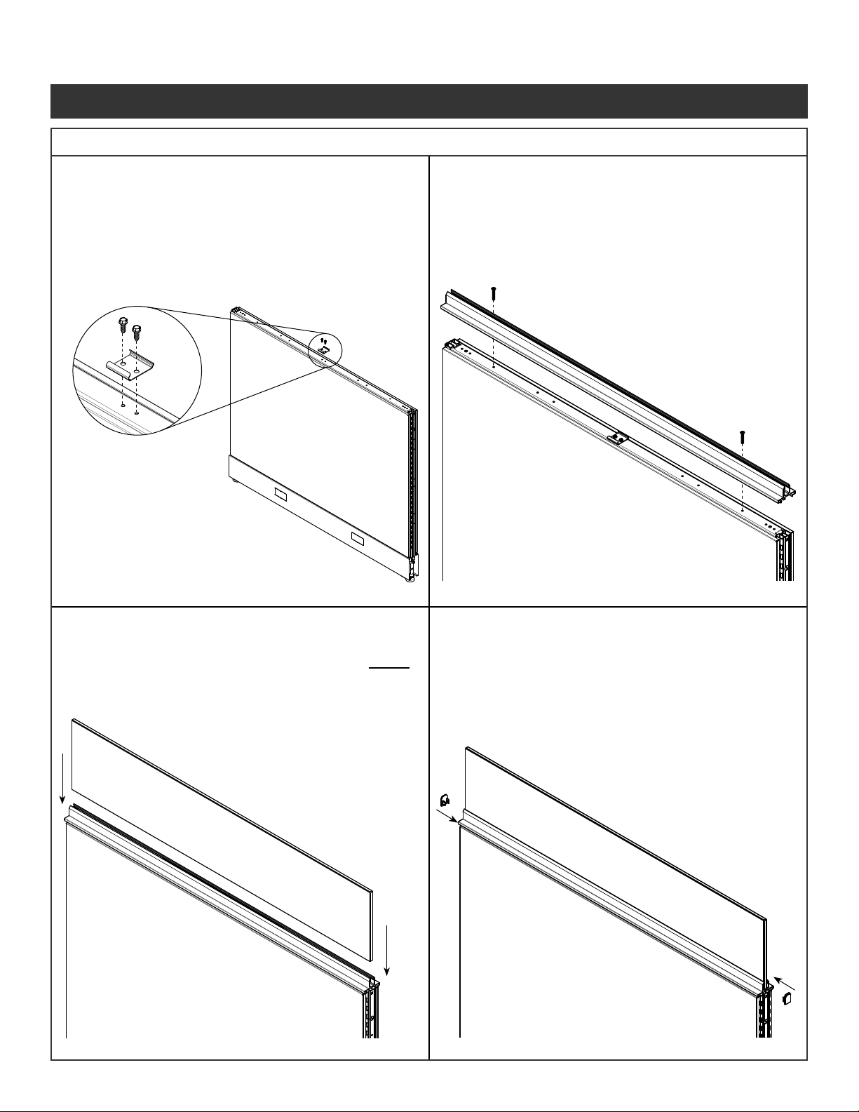
NOTE: Inline clip only required on one side of
panel connection.
Step 1 - Remove the kickplate from one
side of each panel.
Step 2 - Position panels together with
the slotted vertical tubes in
alignment.
Step 3 - Secure the panels at the top by installing
the inline connector strap into slotted
steel tubes of both panels.
Step 4 - Attach the connector to the panels using
two screws (Fastener #1) provided.
Do not over torque.
Step 5 - Secure the panels at the bottom
by inserting a screw (Fastener #1)
through the slot in the glide tower into
the glide tower of the adjacent panel.
Step 6 - Reinstall kickplate.
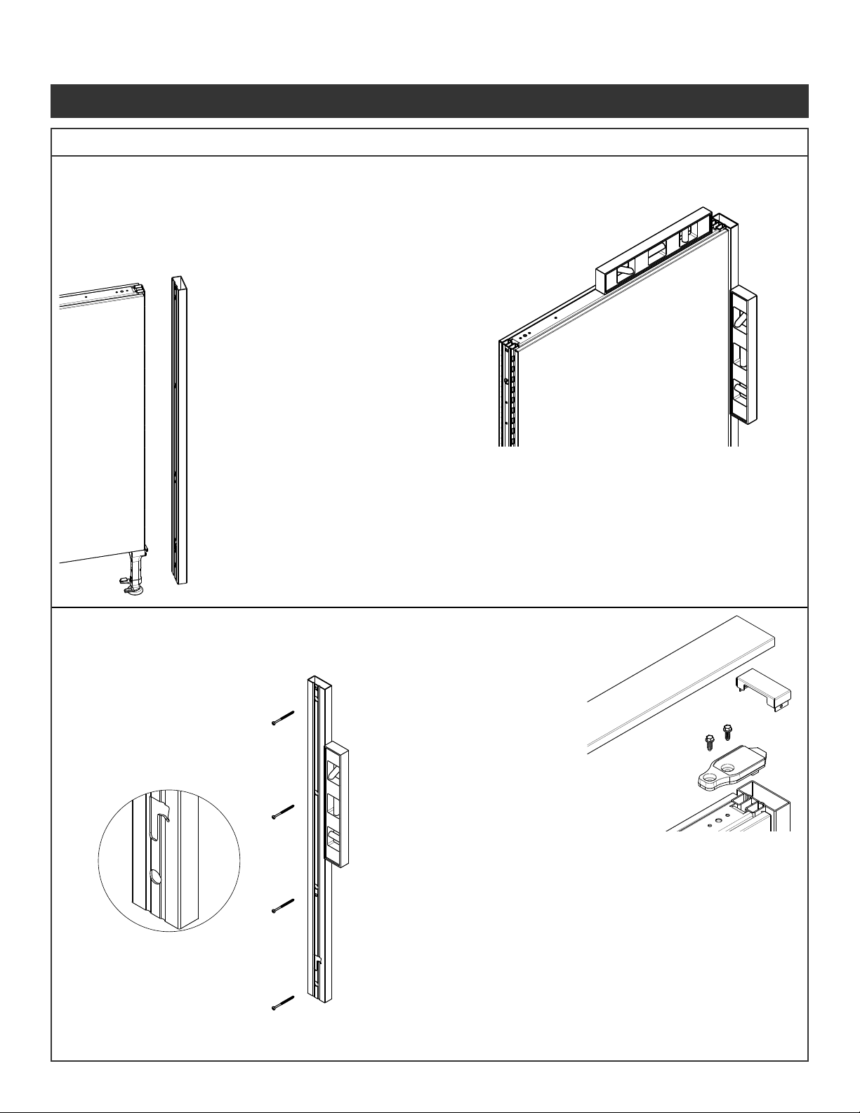
NOTE: Remove pins (Fastener #5) from
stackers for panel to panel connections.
Follow Steps 1 through 3 for current style connection.
Step 4 - Attach the connector to the current style panel
using one screw (Fastener #1) provided.
Do not over torque
Using the inline connector strap locate the hole
over the previous style panel. Using a 9/64 drill bit,
drill pilot hole into top horizontal tube.
Attach the connector to the previous style panel
using one screw (Fastener #1) provided.
Do not over torque.
Follow Steps 5 through 9 for current style connection
Step 7 - Locate position for inline clip.
Position determined by layout and worksurface
supports. Place closet to worksurface height as
possible without interfering with supports.
Step 8 - Use needle nose pliers to grab slots above or
below intended clip location.
Pull verticals together.
Step 9 - Insert bottom prongs of clip at a
slight angle into panel slots.
Rotate clip up so that the top
prongs enter the slot above.
Slide clip down to secure
connection.
Illustration 4. Previous Style Panel to Current
Illustration 3. Panel to Panel Connections
Panel System Installation Packet
343-3890A
(03/17)
Page 4 of 27