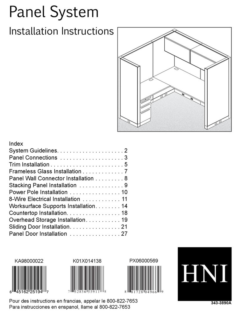
HNI Gallery Panels User manual

Gallery Panels
Installation Instructions
Index
Abound Panel System. . . . . . . . . . . . . . . . . . . . . . . . .......................2
................3
......................5
............ .......................6
......................8
Gallery to Gallery Connections ................ .......................9
Glass Installation ................ ......................
Storage Connection ......................... ......................
.............. ......................
................ ......................
Tackboard Installation .............. ......................
Gallery Stiener Installation ........ ......................
Hardware Chart ............................. ......................
Tools Needed:
3430455100
05/13/2021

Gallery Panels Installation Packet
3430455100Page 2 of 18
Abound Panel System

Gallery Panels Installation Packet
3430455100 Page 3 of 18
Create
End of Run Gallery Panel - Single Panel T & L Conguration
Step 2
Step 1
X
X
Note: Gallery panels can be installed before or after Abound panels are connected. HON recommends attaching a
single spine panel to each gallery panel before connecting entire spine together. (See examples below...)
Recommended process
If o-modular setup is
specied, measure spine
location from end of panel.
Use center slot to align
mounting bracket.
Note: Connector kits attach to sets of pilot holes found on the bottom of each gallery panel. End holes are used when
installing single-sided (L) applications; middle holes are used for dual-sided (T) applications. Installation of the
connector kits is the same for all hole locations.
(G) x2
(G) x4
***IMPORTANT***
Wedge Bracket must be installed between
Mounting Bracket and Gallery Panel for
proper alignment of Trim & Frameless Glass.

Gallery Panels Installation Packet
3430455100Page 4 of 18
End of Run Gallery Panel - Single Panel T & L Conguration (Continued)
Step 3
Step 4
Step 5
Spacer Bracket
Add Spacer Bracket
Remove Plastic
Leveling Block
(A)
(E)
Align bracket
into electrical
hole of frame.
Do not add Spacer
Brackets here

Gallery Panels Installation Packet
3430455100 Page 5 of 18
Create
Mid-Run Blocks & Trim
Step 1
Step 3
Connector Block
Step 2
Step 4
Fully seat into frames
with rubber mallet
(E)

(B) x8
(B) x6
Gallery Panels Installation Packet
3430455100Page 6 of 18
Mid-Run Gallery Panel
Step 1
Note: Top bracket covers slotted
standard holes. If setup requires
an adjacent overhead storage
unit, attach top bracket 15” from
gallery panel top edge.
Step 3
Step 2

(D) x4
Gallery Panels Installation Packet
3430455100 Page 7 of 18
Create
Mid-Run Gallery Panel (Continued)
Step 4
Step 5
Remove breakaway tabs
covering tile lead-in holes.
Bottom nger mounts into
second lowest possible position.
Step 6

Gallery Panels Installation Packet
3430455100Page 8 of 18
XX
Worksurface Connections
Note: Worksurfaces can connect to gallery panels with a Cantilever bracket or an L-Tower bracket.
Method is dependent on application specied.
Step 1
Cantilever Method
L-Tower Bracket Method
Note: Use of level is required when connecting worksurfaces with L-Tower bracket. Spine and gallery panels must
be level before worksurfaces are installed. All L-Tower bracket applications require additional panel-mounted
support to set worksurface height.
Step 1
Note: Worksurfaces with
unsupported spans of
60” or greater require
two L-Tower brackets.
Step 2
Step 3
Step 2
Step 3
(G) x2
(H) x7
Hole locations

Gallery Panels Installation Packet
3430455100 Page 9 of 18
Create
Gallery to Gallery Connections - L & T Return Panels
Overview: Gallery Panels may connect to one another with the use of “L” or “T” RETURN panels. Gallery Return panels
OVERLAP the edge of a PARENT panel, which may be any standard Gallery Panel or another Return panel.
Return panels may be equal or shorter in height to the parent, but not taller.
Installation of Return panels requires template model HRVGTGG (packaged separately).
“L”
Left
“L”
Right
“T”
Symmetric
“T”
Nonsymmetric
Note: Gallery Panels may connect in “L” or “T” applications. “L” panels may face left or right, “T” panels may be
symmetric or nonsymmetric; below are examples of each. All gallery to gallery variations install in a similar way.
Return
Panel Parent Panel
(Standard Gallery Panel)
Return
Parent
Template
HRVGTGG

Gallery Panels Installation Packet
3430455100Page 10 of 18
Step 1
******IMPORTANT******
Do not drill all holes in Template.
Add hole that correlates to
Return Panel height only.
Gallery to Gallery Connections - L & T Return Panels (Continued)
Step 2
Bottom four holes are
required for all panel types.
Parent
Panel
Press template upwards
against bottom edge of
Parent panel for proper
vertical alignment.
Return
Panel
Connector
Bracket
Keyhole
Bracket Remove Connector
to access Hardware

Gallery Panels Installation Packet
3430455100 Page 11 of 18
Create
(J) x4
(K)
Gallery to Gallery Connections - L & T Return Panels (Continued)
Step 3
Step 4
Left Panel Right Panel T Panels

Gallery Panels Installation Packet
3430455100Page 12 of 18
(L) x8
Gallery to Gallery Connections - L & T Return Panels (Continued)
Step 5
Step 6
Step 7
Connector Cover
HRVCGGC
“T” Panels receive
Covers on both faces
Tap lightly on outer
edge with woodblock
for tight tting covers

Gallery Panels Installation Packet
3430455100 Page 13 of 18
Create
Step 1
Glass Installation
Laminate Storage Connection (Closed Back Units)
Step 1
Step 2
X X
X X
(F) x4
Hole Locations
Ribs
Relief
Channels
Step 2
******IMPORTANT******
Gasket can be trimmed with
scissors for proper tup. Cut
to exact channel width to
cover internal panel material.

Gallery Panels Installation Packet
3430455100Page 14 of 18
SCALE 0.450
Laminate Storage Connection (Open Back Units)
Step 1
Step 2
SCALE 2.000
SCALE 2.000
(C) x2
(C) x2

Gallery Panels Installation Packet
3430455100 Page 15 of 18
Create
Metal Storage Connection
Step 1
Step 2
SCALE 0.300
XX
XX
(G) x4
Hole Locations

Gallery Panels Installation Packet
3430455100Page 16 of 18
Tackboard Installation
Step 1
SCALE 0.200
SCALE 0.200
Step 2
SCALE 0.300
SCALE 0.200
X
X

Gallery Panels Installation Packet
3430455100 Page 17 of 18
Create
Note: Gallery panel stiener suggested to be installed after all worksurfaces and supports are installed. This ensures
there will be no interference issues.
Step 1
Step 2
Step 3
Step 4
Gallery Stiener Installation

Gallery Panels Installation Packet
3430455100Page 18 of 18
Hardware Chart
A
B
C
E
G
D
F
H
I
J
K
L
Table of contents
Other HNI Indoor Furnishing manuals
Popular Indoor Furnishing manuals by other brands

BDI
BDI TANAMI 7120 manual

Landscape Forms
Landscape Forms Carousel installation guide

Living & Co
Living & Co COSTA NOVA DINING instruction manual

convenience concepts
convenience concepts 7104090 Assembly instructions

Perfect Choice
Perfect Choice Swivel Dining Chair Assembly instructions

Next
Next DARCY STANDARD BED DOUBLE 126284 Assembly instructions

Baxton Studio
Baxton Studio LCF20182 Assembly instruction

Sauder
Sauder worksense PALO ALTO 427795 manual

Golden
Golden MAXICOMFORT EZ Sleeper PR-761 owner's manual

Office Star Products
Office Star Products BP-BNTV47-WF13 Assembly instructions

Sunjoy
Sunjoy L-BR098PST-A Assembly instructions

PHI VILLA
PHI VILLA THD5-0605-102 Use and care guide