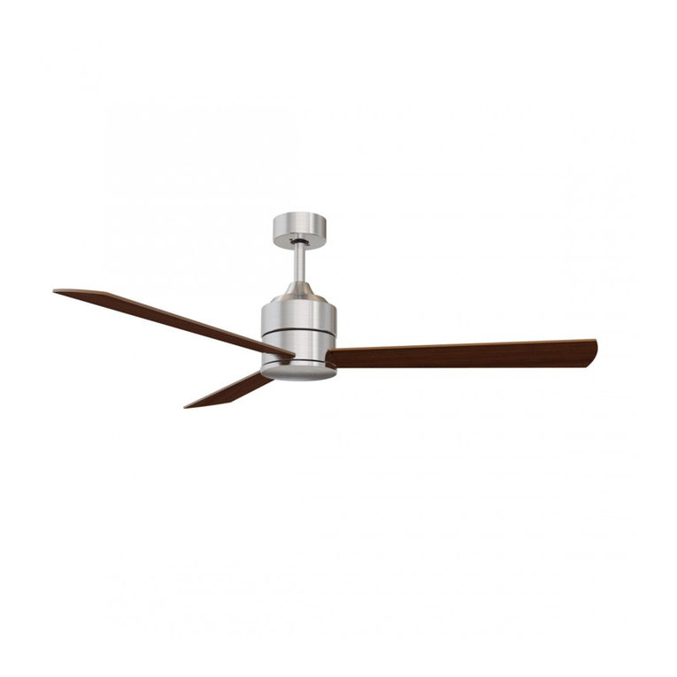
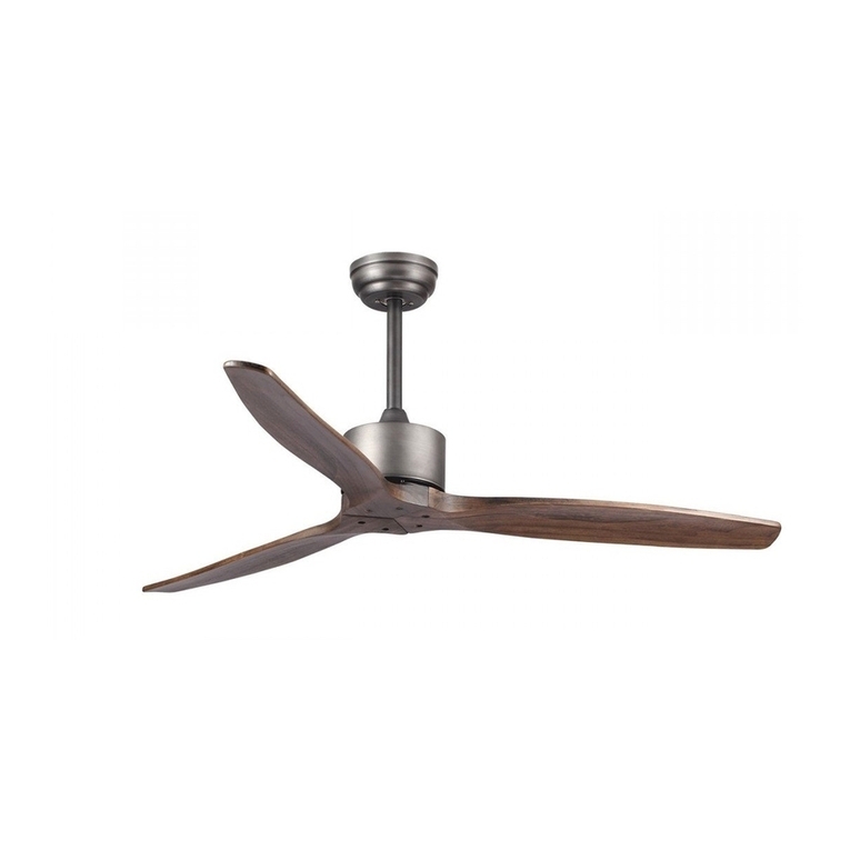
HOFFLIGHTS PASCUA User manual

PASCUA
MANUAL DE INSTALACIÓN
INSTALLATION MANUAL
MANUEL D’INSTALLATION
IMH-104 v.01


ÍNDICE INDEX INDEX
Manual de instalación ventilador 4
Instrucciones de uso del mando a distancia 9
Fan installation manual 12
Remote control user manual 17
Manuel d’installation du ventilateur 20
Mode d’emploi de la télécommande 25
PRECAUCIÓN
LEA LAS INSTRUCCIONES CON ATENCIÓN PARA GARANTIZAR UNA INSTALACIÓN
SEGURA Y UN BUEN FUNCIONAMIENTO DEL VENTILADOR.
EN CASO DE DUDA CONSULTE A UN ELECTRICISTA CERTIFICADO
CAUTION
READ INSTRUCTIONS CAREFULLY FOR SAFE INSTALLATION AND FAN OPERATION.
IF UNSURE CONSULT A QUALIFIED ELECTRICIAN.
PRECAUTION
LISEZ ATTENTIVEMENT LES INSTRUCTIONS POUR GARANTIR UNE INSTALLATION
SÉCURISÉE ET LE BON FONCTIONNEMENT DU VENTILATEUR.
EN CAS DE DOUTE CONSULTEZ UN ÉLECTRICIEN QUALIFIÉ

hofflights.com
4
MANUAL DE INSTALACIÓN
PASCUA
IMH-104 v.01
Gracias por comprar este producto de calidad. Para asegurar su uso y la seguridad, por favor lea y conserve este manual
antes de utilizar el producto.
GRACIAS POR SU COMPRA
SEGURIDAD
1. Para evitar posibles choques eléctricos, corte la luz desde la caja de fusibles o magnetotérmicos antes de empezar con
la instalación del ventilador, su puesta en marcha o la instalación de los accesorios.
2. Lea las instrucciones y los consejos de seguridad con atención antes de instalar el ventilador y conserve estas
instrucciones.
3. Asegúrese de que todas las conexiones son conformes con las normas locales y el código nacional eléctrico (NEC).
Si nunca ha hecho un montaje eléctrico, por favor consulte un electricista acreditado.
4. Asegúrese de seleccionar un sitio en el que su ventilador tenga un espacio despejado para la rotación de las aspas y al
menos 2,3 m (7,5 pies) de distancia entre el suelo y las extremidades de las aspas. El ventilador debe ser instalado a
por lo menos 75 cm (30 pulgadas) de las paredes y de otras estructuras verticales.
5. ADVERTENCIA: La caja eléctrica y el soporte de la vigueta de techo utilizados deben ser fijados y asegurados para
poder soportar al menos 45 kg. (100 libras). Para reducir el riesgo de choque eléctrico o de heridas, se debe montar la
caja eléctrica indicada como siendo compatible con un soporte de ventilador y se deben usar los tornillos proporciona-
dos en el cartón. La caja eléctrica debe instalarse directamente sobre la estructura del edificio.
6. ADVERTENCIA: Para reducir el riesgo de choque eléctrico o de heridas, se debe montar la caja eléctrica indicada
como siendo “compatible con un soporte de ventilador” y se deben usar los tornillos proporcionados en el cartón, la
mayoría de las cajas eléctricas que se usan habitualmente para el soporte de las luminarias no son compatibles para
un soporte de ventilador y han de ser sustituidas. Consulte a un electricista acreditado en caso de duda.
7. Una vez completada la instalación, controle que todas las conexiones sean seguras.
8. Una vez las conexiones eléctricas efectuadas, los conductores deben ser volteados y empujados con cuidado hacia
dentro de la caja eléctrica. Los cables deben ser apartados con el conductor de tierra y la toma de tierra del aparato
por un lado de la caja eléctrica.
9. ADVERTENCIA: Para reducir el riesgo de choque eléctrico o de fuego, no se debe utilizar este ventilador con un
mando fijo de pared o reostato.
10. No utilizar la función inversa hasta que el ventilador se haya parado completamente.
11. No insertar objetos en las aspas cuando el ventilador está funcionando.
12. ADVERTENCIA: Para reducir el riesgo de heridas no plegar los soportes de las aspas (también llamadas “bridas”)
durante el montaje o después de la instalación. No inserte objetos en el giro de las aspas.
13. Para evitar heridas o daños al ventilador o cualquier otro elemento, tenga cuidado al trabajar en esta zona o cuando
limpie el ventilador.
14. No use agua o detergente para limpiar el ventilador o las aspas. Un trapo seco o ligeramente humedecido será sufi-
ciente para su limpieza.
WARRANTY
MOTOR
10
2,3
m
IP20
DC
MOTOR 5SPEED
ABS
BLADES
M
15-20
m2
W
Motor V RPM
Airflow
(CFM) ØxH (mm.) Kg
5.0150.0211 32 100-265 180 5500 1320x305 4,2
WARRANTY
MOTOR
10
2,3
m
IP20
DC
MOTOR 5SPEED
ABS
BLADES
M
15-20
m2
3K
4K5
6K
W
Motor V RPM
Airflow
(CFM)
W
LED K CRI ØxH (mm.) Kg
5.0150.1211 32 100-265 180 5500 18 3K-4K5-6K 80 1320x305 4,5

MANUAL DE INSTALACIÓN
PASCUA
5hofflights.com IMH-104 v.01
Desenvuelva el ventilador y verifique el contenido de la caja. Debe encontrar lo siguiente:
1Soporte de fijación
2Tija/Bola de suspensión
3Florón
4Tapa de gancho
5Bloque motor ventilador
6Kit de tornillos
AFerretería del soporte de fijación (tuercas
para cables, arandelas de goma)
BFerretería para los soportes de aspas
7Receptor + mando a distancia
8Aspas
ANTES DE LA INSTALACIÓN
HERRAMIENTAS Y MATERIAL NECESARIO
1Destornillador Phillips
2Destornillador para aspas
3Llave ajustable
4Escalera de mano
5Cortador de cables
6Cinta aislante
8
1
2
3
4
5
6
7
NOTA: Las importantes medidas e instrucciones de seguridad descritas en el manual no pretenden responder a todas las
situaciones posibles que puedan ocurrir. El sentido común y la prudencia son factores necesarios para la instalación y la
puesta en marcha de este ventilador.
NOTA: Este producto no debe ser usado por personas (incluyendo a niños) con capacidad física reducida, capacidades
sensoriales o mentales diferentes o reducidas, o con falta de experiencia o conocimiento, salvo si aquellas personas son
vigiladas o entrenadas para hacer funcionar el aparato por una persona responsable de su seguridad.
NOTA: Los niños deben ser vigilados para asegurarse de que no estén utilizando el ventilador como un juguete.
NOTA: Debe instalar un magnetotérmico o interruptor que desconecte todos los polos de potencia en al menos 3 mm entre
cada polo.

hofflights.com
6
MANUAL DE INSTALACIÓN
PASCUA
IMH-104 v.01
Todas las acciones deben hacerse sólo una vez que se haya cortado la luz quitando los fusibles o apagando los magneto-
térmicos.
Su ventilador admite una tija alargadora para bajar el ventilador de su posición original. Tijas de extensión, desde 30,5 cm
(12”) hasta183 cm (72”), están disponibles si necesita bajar más su ventilador. (Normalmente es el caso estancias con techos
muy altos).
INSTALACIÓN DEL VENTILADOR
El soporte de techo debe ser firmemente apretado a una superficie plana. El
sitio de la colocación debe permitir soportar un peso de diez veces el peso del
ventilador fijo. Si tiene cualquier duda para saber si el sitio donde quiere co-
locar el ventilador tendrá esta capacidad de carga. Por favor contacte nuestro
servicio telefónico de asistencia o cualquier autoridad competente que le
pueda asesorar En la mayoría de los casos dos tornillos colocados en la viga
de madera son más que suficientes para soportar su ventilador de techo.
El soporte de fijación debe ser atornillado dentro de la viga con los dos
tornillos de madera proporcionados. Las arandelas proporcionadas deben ser
utilizadas en el siguiente orden:
Cabeza de tornillo>arandela redonda>arandela de resorte>soporte de
fijación>techo. Atornille el soporte de fijación en el techo y asegúrese de que
todas las conexiones estén seguras para evitar cualquier caída del ventilador.
Las fijaciones deben ser atornilladas en la viga y no en el yeso. Afloje los dos
tornillos de la cubierta del soporte de fijación.
INSTALACIÓN DEL SOPORTE
1
Desatornille la tija y afloje la bola de suspensión. Verá
un “PERNO ESFÉRICO” en la tija, retírelo así como la
bola de suspensión de la tija.
Retire la clavija de la tija y del hueco del bloque motor.
Si va a utilizar una tija más larga
desde 12” hasta 72” (30,5 cm hasta183 cm) inserte el
cable dentro de la tija más larga.
INSTALACIÓN DEL FLORÓN Y DE LA TIJA
2
Pase los cables que salen dese arriba de motor a través de
la tija hasta que salgan del otro lado en la parte de arriba
de la tija.
Inserte la tija en el bloque motor. Gire suavemente para
alinear los agujeros del bloque motor con los de la tija.
Empuje el tornillo en el hueco del bloque motor teniendo
cuidado de no pinchar o dañar los cables. Coloque en su sitio
reemplazando el R-pin.

MANUAL DE INSTALACIÓN
PASCUA
7hofflights.com IMH-104 v.01
Levante el ventilador hacia el soporte, dirija la bola dentro del lado del soporte
y bájelo dentro del hueco del soporte. Gire la bola hasta que la ranura del lado
de la bola se alinee con la prominencia del extremo superior del hueco Una vez
alineado el ventilador debe bajar despacio y colocarse en la posición correcta.
Sirve para prevenir la rotación de la tija y del ventilador cuando el aparato esté
en marcha.
Coloque el receptor dentro del soporte de fijación para su conexión.
Conecte el conector rápido del ventilador al recepctor del mando a distancia, por
favor tome nota, la conexión por cable debe de ser “marrón sobre marrón, azul
sobre azul, naranja sobre naranja, verde/amarillo sobre verde/amarillo”. El co-
nector rápido no ha podido ser empujado y puede causar daños en el ventilador
si los cables están mal conectados.
Conecte el conector rápido del soporte de fijación.
A.C. Potencia de entrada del mando a distancia.
“Marrón sobre marrón, azul sobre azul, verde/amarillo sobre verde/amarillo”
COLGAR EL VENTILADOR EN EL SOPORTE
INSTALACIÓN DE LAS ASPAS
3
Apriete todos los tornillos en esta etapa. Sirve para evitar que la tija y el ventilador se
muevan el uno contra el otro. También permite mantener un buen conducto detierra
dentro del ventilador, lo cual es importante para la seguridad del equipo.
El no apretar bien los tornillos puede causar una fuerte oscilación del motor.
Una vez la etapas arriba mencionada acabadas, coloque el agujero del soporte sobre
la tija, inserte el PERNO ESFÉRICO dentro de la tija, levante el soporte. A continuación,
apriételos firmemente.
1
Hay 3 tornillos que sostienen la carcasa superior
del ventilador en el motor. Afloje estos 3 tornillos y
empuje la carcasa superior hacia arriba.
2
Alinee los agujeros y ate la aspa al bloque motor
con los tornillos proporcionados.
Repita el procedimiento para las demás aspas.
3
Después de que todas las aspas estén bien sujetas al mo-
tor, empuje la carcasa superior hacia abajo sobre el motor
y fije la carcasa superior del ventilador con 3 tornillos.
1
2
3

hofflights.com
8
MANUAL DE INSTALACIÓN
PASCUA
IMH-104 v.01
INSTALACIÓN DE KIT LUZ
1
Retire los tres tornillos de la placa del motor, y guarde
todos los cables con cuidado dentro de la placa de
conexiones. Monte y alinee el agujero detrás de la LED
a tres agujeros de la placa de conexiones del motor ver
dibujo. Atornille a continuación firmemente del agujero
de la LED, por favor asegúrese de que el kit de luz no
se mueva una vez atornillado.
2
Conecte el conector del kit de luz y del ventilador
3
Atornille el kit de luz al cuerpo del ventilador.
Asegúrese de que la lámpara no esté demasiado
apretada.

MANUAL DE INSTALACIÓN
PASCUA
9hofflights.com IMH-104 v.01
HACER LAS CONEXIONES ELÉCTRICAS
ADVERTENCIA: Antes de hacer el cableado, asegúrese de haber desconectado todas las fuentes de suministro de electricidad.
Su ventilador es entregado con un mando a distancia con frecuencia radio y el ventilador no tiene un botón para controlar la velocidad,
éste sólo puede funcionar con el mando a distancia. Encontrará el mando a distancia dentro del cartón.
UTILIZAR SU VENTILADOR
MANDO A DISTANCIA
Encienda y verifique el funcionamiento del ventilador
1Interruptor indicador
2Control de velocidad
3Apagado del ventilador
4Temporizador
5Interruptor de luz.
Batería:12V-23A
NOTA
1. Por favor espere unos instantes entre cada acción.
2. Por favor manipule el transmisor con cuidado,
asegúrese de dejarlo caer o exponerlo al agua, a
mucha humedad o en un sitio cerca de una fuente
de calor. Una manipulación errónea puede provocar
una avería y anular la garantía.
3. El mando a distancia funcione con Radiofrecuencia
por lo que no es necesario dirigir el mando hacia el
ventilador para activar la funcionalidad inalámbrica.
HOUSEHOLD
AC IN 220-240V
L
AC IN 220-240V
N
yellow/green
Remote
ControlUnit
FAN
Bracket
yellow/green yellow/green
Blue
Light live-wire Power supply live-wire
Brown
Black wire
White
Light neutral-wire Power supply neutral-wire
Blue
Pink
To Motor wire Ground wire
Antenna wire
Yellow/Green
Grey
To Motor wire Red
To Motor wire
12
3
4
5

hofflights.com
10
MANUAL DE INSTALACIÓN
PASCUA
IMH-104 v.01
RESOLUCIÓN DE PROBLEMAS
1. Verifique todos los fusibles o magnetotérmico. Sustituya los que falten.
2. Apague la corriente eléctrica y verifique todas las conexiones de los cables del ventilador y del interruptor.
1. Puede que el ventilador esté girando en sentido contrario por lo que el aire se va hacia arriba. (Modo invierno)
2. Puede que la habitación tenga elementos que obstruyen el flujo del aire.
3. Puede que el ventilador sea demasiado pequeño para la habitación.
1. Una oscilación leve es considerada como aceptable y no debería ser considerada
como un defecto El uso de cualquier kit de luz, especialmente uno grande con 4 o 5
bombillas provocará habitualmente una oscilación.
2. Asegúrese de que el soporte de fijación esté apretado a la caja de empalme/al techo
y de que no se mueva en absoluto. Apriete los tornillos de ser necesario.
3. Asegúrese de que todos los tornillos que retienen las y el bloque motor estén apre-
tados. Asegúrese de que los tornillos de kit de luz/del cristal estén apretados.
4. Un movimiento leve es normal. Sin embargo, intercambiar un par de aspas adyacen-
tes (lado a lado) puede repartir el peso para obtener un mejor funcionamiento.
5. Si un kit de equilibrado es proporcionado, utilícelo si necesario.
1. Deje siempre unos días a su ventilador para que “se adapte” a velocidad mediana o alta. Intente identificar la proce-
dencia exacta del ruido escuchando atentamente desde diferentes ángulos (Aspas, motor, kit de luz, etc.). El ruido del
ventilador puede proceder del kit de luz.
2. Asegúrese de que todos los tornillos de montaje del ventilador y del kit de luz estén bien apretados y correctamente
enroscados. De no ser así, retírelos y vuélvalos a apretar. Apriete estos tornillos al menos una vez al año porque
pueden irse soltando poco a poco con el tiempo y provocar un chasquido.
3. Asegúrese de que el kit de luz esté firmemente apretado en el ventilador y que todos los tornillos del cristal estén
apretados sólo manualmente. No se deben de apretar con un destornillador.
4. Asegúrese de que el soporte de fijación esté perfectamente enganchado a la caja de empalme.
5. Asegúrese de que las tuercas para cables de la caja eléctrica o de la cubierta no se golpeen entre sí o contra la caja de
pared. Envuélvalos en cinta aislante de ser necesario.
6. El uso de un reostato estándar o de un control de pared variable provocará siempre distorsiones armónicas o un
zumbido. Muchos motores de ventiladores no funcionan en silencio con un control de pared variable. Si desea utilizar
un control de pared silencioso, use únicamente los que sean certificados y de 3 velocidades.
7. Asegúrese de que el florón no esté tocando el techo.
8. Compruebe que los tornillos de las aspas al bloque motor estén apretados y que las arandelas previstas para tal
efecto hayan sido usadas.
9. Asegúrese de que todas las bombillas estén bien enroscadas.
EL VENTILADOR NO ARRANCA:
EL VENTILADORPERO NO MUEVE MUCHO AIRE:
EL VENTILADOR TIEMBLA U OSCILA:
EL VENTILADOR HACE RUIDO:
Touching
ceiling

MANUAL DE INSTALACIÓN
PASCUA
11hofflights.com IMH-104 v.01
1. Los movimientos naturales del ventilador pueden provocar conexiones sueltas. Un ruido de chasquido o de golpeteo
es una señal de que los tornillos se están soltando. Compruebe las conexiones del soporte, de las aspas dos veces al
año y apriételos según las necesidades. Asegúrese de que todos los tornillos del cristal enganchado al kit de luz sean
apretados manualmente. No utilice un destornillador ni pinzas para apretar los tornillos del cristal.
2. Limpie su ventilador periódicamente. Quite el polvo con un trapo o una brocha. Los acabados del metales llevan un
laqueado especial para prevenir las manchas.
3. Nunca deberá engrasar su ventilador. Su rodamientos permanentemente sellados proporcionarán un funcionamiento
silencioso y sin fallo durante muchos años.
4. Asegúrese de que la corriente esté apagada desde la caja de fusibles o del magentotérmico antes de hacer cualquier reparación.
MANTENIMENTO
Su ventilador puede mostrar problemas de oscilación cuando está en marcha debido a anomalías en las aspas o en los
soportes de aspas. Asimismo, un montaje erróneo o rodamientos torcidos pueden causar problemas adicionales. El kit de
equilibrado puede usarse en caso de problemas de oscilación.
KIT DE EQUILIBRADO PARA VENTILADOR DE TECHO
1. Asegúrese de que todas las aspas estén firmemente apretadas dentro del soporte de aspa.
2. Asegúrese de que todos los soportes de aspas estén firmemente apretados al bloque motor Controle que el nivel de
las aspas sea el mismo para todas.
3. Al mirar el ventilador desde arroba hacia abajo, verifique que ningún soporte de aspa esté doblado y de que todas las
aspas estén correctamente colocadas en su sitio. Se puede corregir apretando ligeramente el soporte de aspa hacia
arriba o abajo para colocarla correctamente.
4. Utilice un medidor para comprobar la posición de las aspas. Coloque el medidor verticalmente contra el techo y
contra el borde exterior de la aspa. Note la distancia desde el borde de la aspa hasta el techo. Gire despacio las
aspas con precaución y manualmente para controlar las demás aspas. Si la aspa sigue desalineada, puede plegar
ligeramente el soporte hacia arriba abajo para alinear la aspa con las demás.
Si después de seguir todas estas etapas el problema de oscilación sigue, se puede utilizar el kit de equilibrado. Siga las
instrucciones listadas a continuación:
- Gire el ventilador y ajuste la velocidad (generalmente alta) en la cual se nota más la oscilación.
- Apague el ventilador. Seleccione una aspa y coloque el clip de equilibrado encima, entre el soporte de aspa y el borde
exterior de la aspa.
- Encienda el ventilador. Observe para ver si la oscilación ha mejorado o empeorado. Apague de nuevo el ventilador y
ponga el clip en otra aspa y rehaga la prueba. Repita estas acciones con todas las aspas y luego tome nota de qué aspa es
la que permite mejorar más.
- Mueva el clip en la aspa que ha mostrado la mayor mejora. Mueva el clip hacia el interior o el exterior de la aspa para
encontrar la posición en la cual el clip da los mejores resultados.
- Después mueva el clip e instale el peso de balanceo en la punta de la aspa en la línea central cerca del punto donde se
había colocado el clip. Utilice un cuchillo afilado o una navaja para separar los pesos
PRECAUCIÓN: Manténgase alejado de las aspas. Si el clip, por cualquier motivo, no está asegurado, puede causar heridas.
PREFACIO
Este producto al final de su vida no debe ser tirado junto con la basura doméstica normal sino llevado a un punto de
reciclaje adaptado para los aparatos eléctricos o electrónicos. El símbolo en el producto, el manual de instrucciones o las
piezas del embalaje.
Los materiales son reciclados según su identificación. Gracias al reciclaje o a cualquier otra forma de evitar malgastar,
nuestra contribución a la protección del medio ambiente es importante.
Consulte la entidad administrativa local u autoridad competente.
NOTAS SOBRE LA PROTECCIÓN DEL MEDIO AMBIENTE

hofflights.com12
INSTALLATION MANUAL
IMH-104 v.01
PASCUA
Thank you for purchasing this quality product. To ensure correct function and safety, please read and save all instructions
before using the product.
1. To avoid possible electric shock, turn off the electricity at the main fuse box or circuit panel before you begin the fan
installation or before servicing the fan or installing accessories.
2. Read all instructions and safety information carefully before installing your fan and save these instructions.
3. Make sure all electrical connections comply with local codes or ordinances and the National Electrical Code. If you are
unfamiliar with electric wiring, please use a qualified and licensed electrician.
4. Make sure you have a location selected for your fan that allow clear space for the blades to rotate, and at least 7,5 feet of
clearance between the floor and the fan blade tips. The fan should be mounted at least 30 inches from walls or other
upright structures.
5. WARNING: The outlet box and ceiling support joist used must be securely mounted, and capable of supporting at least
100 pounds. To reduce the risk of fire, electric shock or personal injury, mount to the outlet box marked acceptable
for fan supported and use mounting screws provided with the outlet box. The box must be supported directly by the
building structure.
6. WARNING: To reduce the risk of fire, electric shock or personal injury, mount to outlet box marked “acceptable for fan
support” and use mounting screws provided with the outlet box most outlet boxes commonly used for the support of
lighting fixtures are not acceptable for fan support and may need to be replaced. Consult a qualified electrician if in
doubt.
7. After installation is complete, check that all connections are absolutely secure.
8. After making electrical connections, spliced conductors should be turned upward and pushed carefully up into outlet
box. The wires should be spread apart with the grounded conductor and the equipment-grounding conductor on one
side of the outlet box.
9. WARNING: To reduce the risk of electrical shock and fire, do not use this fan with any solid-state fan speed control
device, or rheostat.
10. Do not separate the reverse switch until the fan has come to a complete stop.
11. Do not insert anything into the fan blades while they are rotating.
12. WARNING: To reduce the risk of personal injury, do not bend the blade brackets (also referred to as “flanges”) during
assembly or after installation. Do not insert objects in the path of the blades.
13. To avoid personal injury or damage to the fan and other items, be cautious when working around or cleaning the fan.
14. Do not use water or detergent when cleaning the fan or fan blades. A dry dust cloth or lightly dampened cloth will be
suitable for most cleaning.
THANK YOU FOR YOUR PURCHASE
SAFETY TIPS
WARRANTY
MOTOR
10
2,3
m
IP20
DC
MOTOR 5SPEED
ABS
BLADES
M
15-20
m2
W
Motor V RPM
Airflow
(CFM) ØxH (mm.) Kg
5.0150.0211 32 100-265 180 5500 1320x305 4,2
WARRANTY
MOTOR
10
2,3
m
IP20
DC
MOTOR 5SPEED
ABS
BLADES
M
15-20
m2
3K
4K5
6K
W
Motor V RPM
Airflow
(CFM)
W
LED K CRI ØxH (mm.) Kg
5.0150.1211 32 100-265 180 5500 18 3K-4K5-6K 80 1320x305 4,5

INSTALLATION MANUAL
13hofflights.com IMH-104 v.01
PASCUA
BEFORE INSTALLATION
Unpack your fan and check the contents.You should have the following:
1Mounting Bracket
2Down rod /Ball Assembly
3Ceiling Canopy
4Yoke Cover
5Fan Housing , and motor
6Screw Package
AMounting bracket hardware (wire nuts ,
rubber washers)
BBlade arm attachment hardware
7Receiver + remote Control
8Blades
TOOLS AND MATERIALSREQUIRED
1Phillips screw driver
2Blade screw driver
3Adjustable pliers orwrench
4Step Ladder
5Wire cutter
6Electrical tape
NOTE: The important safety precautions and instructions appearing in the manual are not meant to cover all possible
conditions and situations that may occur. It must be understood that common sense and caution are necessary factors in
the installation and operation of this fan.
NOTE: This product is not intended for use by persons (including children) with reduced physical, sensory or mental capa-
bilities are different or are impaired, or lack of experience or knowledge, unless such persons are supervised or trained to
operate the appliance by a person responsible for their safety.
NOTE: Children should be supervised to ensure that they do not use appliances as a toy.
NOTE: You must install a switch or circuit breaker that disconnects all poles power of at least 3mm between each pole.
8
1
2
3
4
5
6
7

hofflights.com14
INSTALLATION MANUAL
IMH-104 v.01
PASCUA
All electrical work should only be undertaken after disconnection of the power by removing fuses or turning off the circuit
breaker to ensure all pole isolation of the electrical supply.
Your fan is a drop rod fan in this situation the drop rod assembly is used to lower the fan down from it’s mounting position
slightly. Extension rods, ranging from 30,5 cm (12”) to 183 cm (72”), are available if you need to lower your fan further. (This
is normally the case in conservatories or rooms with very high ceilings.)
INSTALLING THE FAN
The hanger bracket should be screwed on to a firm flat surface. The fixing
location must be able to withstand ten times the static weight of the fan.
If you have any doubts as to the ability of your intended fixing location to
be able to withstand this loading. Please contact our service help- line or
another competent authority to advise you. In most situation two wood
screws screwed into a wooden joist is more than adequate to support your
ceiling fan.
The hanger bracket should be screwed onto the joist with the two wood
screws provided. The washers provided should go in the following sequence:
Screw head > round washer > spring washer>Hanger bracket > Ceiling.
Screw the
hanger bracket to the ceiling and make sure all connections are secure to
prevent the fan from falling. Fixings must screw into a joist and not just the
plasterboard. Loosen the two canopy screws from the hanger bracket.
HANGER BRACKETINSTALLATION
INSTALLING CANOPY AND DROP ROD ONTO THE FAN
1
Unscrew the screw on the drop rod hanger ball, then
loosen the hanger ball. A “BALL PIN” will be seen on
the drop rod, remove it and the hanger ball from the
rod.
Remove the cotter pin and split pin from the drop rod
boss of the fan. If a longer drop rod 30,5 cm (12”) to 183
cm (72”), is going to be used transfer the ball joint and
the earth wire to the longer rod.
2
Put the drop rod pass the electrical supply leads from the top
of the motor through the drop rod until they exit at the top of
the rod.
Insert the drop rod into the drop rod boss on top of the motor
casing. Turn gently to align the holes in the boss with those
in the rod. Ease the bolt pin through the boss and the rod
taking care not to pinch or damage any cables. Fix in place by
replacing the R-pin.

INSTALLATION MANUAL
15hofflights.com IMH-104 v.01
PASCUA
Lift the fan up to the hanger bracket, steer the ball in from the side of the
bracket and lower it into the recess of the bracket. Rotate the ball around until
the groove in the side of the ball aligns with the protrusion on the upper edge of
the recess. When aligned the fan should drop slightly as it assumes it’s correct
position. This is to prevent rotation of the rod and fan when the unit is working
After set up the code switch, put the receiver through the hanging bracket for
wiring connecting
Connect the push connector of fan to remote control receiver, please be noted,
the wire position need to be “brown to brown, blue to blue, org to org, green/
yellow to green/yellow”. The push connector could not be pushed in and will
cause fan damage if the wire position iswrong.
Connect the push connector of hanging bracket to.
A.C. Input power of remote control.
“Brownto brown; blue to blue, green/yellow to green/yellow”
HANGING THE FAN TO BRACKET
INSTALLING BLADE
3
Tighten all set screws at this point. This prevents the rod and the fan moving in relation to one and other.
It also assists in maintaining a good earth continuity through the fan, which is important to the safety
of the unit.
Failure to tighten the locking screws down may cause the motor to oscillate badly
The above steps are all finished, put the hanger ball onto the drop rod, inserted the BALL PIN into drop
rod, lift up the hanger ball. Then, screw them down firmly
1
There are 3 screw holding the top fan housing on
the motor. Loosen these 3 screws and push the top
housing upward
2
Align holes and fasten the blade to the motors with
provided screws. Repeat procedure for remaining
blades
3
After all the blades are securely fastened to the
motor , push the top housing down on the Motor
and fasten the top fan housing with 3 screws.
1
2
3

hofflights.com16
INSTALLATION MANUAL
IMH-104 v.01
PASCUA
LIGHT KIT INSTALLING
1
1 Take down the three screws from connect plate of
motor, please tidy up all the wires carefully into con-
nect plate. Assemble and align the k-hole on the back
of Led light to the three screws on the connect plate
of motor, please see the picture. Then screw the three
screws tightly from hole on the LED plate, please make
sure the light kit can’t be moved after screwing.
2
Connect the push plug from light kit and fan
3
Screw lamp shade into fan housing. Make sure lamp
shade is secure but not overly tight

INSTALLATION MANUAL
17hofflights.com IMH-104 v.01
PASCUA
MAKE THE ELECTRIC CONNECTIONS
WIRING INSTRUCTIONS :
Before doing wiring, ensure that you have all pole disconnection of the electricity supply.
Your fan is supplied with a radio frequency remote control unit, and the fan does not have a pull switch for speed control,
the fan can only be controlled by remote control. You can find the unit in the box.
USING YOUR CEILING FAN
REMOTE CONTROL
Turn on the power and check the operation of the fan
1Switch indicator
2Speed controller
3Fan Shutdown
4Timer
5Lamp Switch
Battery for switch: 12V-23A
NOTE
1. Please allow a moment between each operation.
2. Please handle the transmitter with care, be sure not to
drop or expose it to water, high humidity or place whe-
re is too close to a heating element. Improper handling
may result in malfunction and voidthe warranty.
3. The remote control is operated by Radio Frequency, so,
it won’t be Necessary to point this unit at the ceiling
fan while activating the Handset functionalbutton.
HOUSEHOLD
AC IN 220-240V
L
AC IN 220-240V
N
yellow/green
Remote
ControlUnit
FAN
Bracket
yellow/green yellow/green
Blue
Light live-wire Power supply live-wire
Brown
Black wire
White
Light neutral-wire Power supply neutral-wire
Blue
Pink
To Motor wire Ground wire
Antenna wire
Yellow/Green
Grey
To Motor wire Red
To Motor wire
12
3
4
5

hofflights.com18
INSTALLATION MANUAL
IMH-104 v.01
PASCUA
TROUBLE SHOOTING
1. Check all fuses or circuit breakers. Replace if missing.
2. Turn off electrical power and check all wire connections to fan and in switch housing.
1. The fan may be running in reverse, so air is directed upward. (Winter mode)
2. The room may contain items that obstruct the air flow.
3. The fan may be too small for size of the room.
1. Use of standard light rheostat or continuously variable fan speed wall control will always cause harmonic distortions,
or a humming noise. Many fan motors do not work quietly with solid state variable controls. If a quiet wall control in
desired, use only 3-speed approved wall controls.
2. Always allow a few days “break in” time for any new fan at medium or high speed. Try to diagnose the exact location of
the noise by listening carefully from several sides (blades, motor, light kits, etc.). Fan noise can come from a light kit.
3. Make sure all screws in the fan assembly and light kit are tight and properly threaded. If not, back out and retighten.
Tighten these screws at least once a year because they may loosen slowly over time and cause a clicking noise.
4. Make sure the light kit is securely fastened to the fan, and all glass screws are finger tightened only. Do not tighten
with pliers or a screw driver.
5. Make sure mounting bracket is installed snugly to junction box.
6. Make sure wire nuts in switch housing or canopy are not rattling against each other or against wall of housing. Wrap
with electrical tape if necessary.
7. Make sure the canopy is not touching the ceiling.
8. Assure that the screws fastening blade arm to motor are tight and the lock washers provided for that purpose have
been used.
9. Make sure all light bulbs are fully screwed in.
FAN WILL NOT START:
FAN TURNS BUT DOES NOT MOVE MUCH AIR:
FAN SHAKES OR WOBBLES:
FAN IS NOISY:
1. A small amount of wobble is considered acceptable and should not be considereda defect. Use of
Any light kit, especially a large 4 or 5 light kit will usually inducesome wobble.
2. Make sure the mounting bracket is tight at junction box/ceiling with no movement at all. Tighten screws if necessary.
3. Make sure all screws holding the blades to the blade arm and blade arm to motor are tight.Make sure light kit/glass
screws are tight.
4. Some fan movement is normal. However, interchanging an adjacent(side-by-side) bladepair may redistribute the
weight and result in smoother operation.
5. If a balancing kit is provided, use it if needed. Touching
ceiling

INSTALLATION MANUAL
19hofflights.com IMH-104 v.01
PASCUA
1. The fan’s natural movements may cause some connections to work loose. A clicking or rattling noise is a certain sign
of loosening screws. Check the support connections, brackets and blade attachments twice a year, and tighten all
screws as necessary. Make sure all screws attaching the glass to the fitter on the light kit are finger tight. Do not use a
screw driver or pliers to tighten glass screws.
2. Clean your fan periodically. Use only a cloth dampened with a mild detergent solution. Never use solvents. Dust with a
soft cloth or brush. Metal finishes are finished with a lacquer to prevent tarnishing.
3. You will never need to oil your fan. Its permanently sealed bearings will provide silent, trouble free operation for many
years.
4. Make sure the power is turned off at the main fuse or circuit panel before you attempt any repairs.
MAINTENANCE
Your ceiling fan may sometimes have wobbling problems when operating due to irregularity in the blades or the blade
holders. Also, improper assembly in the mounting system or crooked bearings may cause some additional problems. This
balancing kit can be used to fix wobbling problems.
DYNAMIC BLADE BALANCING KITFOR CEILING FANS
1. Make certain that all blades are firmly screwed into the blade holder.
2. Make sure that all blade holders are firmly secured tothe motor housingand check that the pitch of blade holders are
all the same.
3. By looking up at the fan from below, check and be certain that none of the blade holders are bent and that none of the
blades are out of position. A correction can be made by very gently bending the blade holder back intoposition.
4. <Use a yardstick to check the blade tracking. Put the yardstick up against the ceiling vertically and against the outsi-
deleading edge of a blade. Note thedistance of the edge of blade to the ceiling. Carefully turn the blades slowly by hand to
check the remaining blades. If the blade is not in alignment, theblade holder may be gently bent up or down to be in line
withtheother blades.
After followingallthestepsandifthewobblingproblemisnotsolved, a dynamic balancing needs to be done by balancing kit.
Follow the procedure listed below:
- Turn the fan on and adjust the speed control (usually high speed) setting to the speed which creates the greatest wobble.
- Turn the fan off. Select one blade and place the balance clip on it, halfway between theblade holder and the blade tip on
the rear edge of the blade.
- Turn the fan on. Watch to see if the wobble is improved or worsened. Turn the fan off again and move the clip to another
blade and test again. Repeat this process with all blades and then note the blade which is the most improved.
- Move the clip back to the blade which showed themost improvement. Move the clip inward and outward on this blade and
operate the fan to find the position where the clip gives the most improvement.
- Next remove the clip and install a balancing weight to the top of the blade along the center line near the point where the
clip was positioned. Use a sharp knife or razor to separatetheweights.
CAUTION: Stay clear of the blades. If the clip, for any reason, is not secure, injury couldresult
PREFACE
This product may be at the end of his life rather than the normal household waste will be sonderm at a collection point for
the recycling of electrical and electronic equipment will be delivered. The symbol on the product, the instruction manual
or packaging recalls.
The materials are recycled, according to their identification. With the reuse of recycling or other forms of recovery of waste
afford a important contribution to protect our environment.
Please ask at the municipal disposal of the competent authority.
NOTES ON ENVIRONMENTAL PROTECTION

hofflights.com20
MANUEL D’INSTALLATION
IMH-104 v.01
PASCUA
Merci d’avoir acheté ce produit de qualité. Pour une utilisation correcte et sécurisée, veuillez lire et conserver ces instruc-
tions avant d’utiliser le produit.
MERCI POUR VOTRE ACHAT
CONSEILS DE SÉCURITÉ
1. Pour éviter tout risque d’électrocution, coupez le courant du boîtier à fusibles ou du panneau de disjoncteurs avant de
commencer l’installation ou la mise en marche du ventilateur ou encore l’installation des accessoires.
2. Lisez attentivement toutes les instructions et les informations de sécurité avant d’installer votre ventilateur et conser-
vez ces instructions.
3. Assurez-vous que l’installation électrique est conforme aux normes locales ou au code national d’électricité américain
(NEC). Si vous n’avez jamais fait d’installation électrique, veuillez contacter un électricien qualifié.
4. Assurez-vous d’avoir choisi un endroit d’installation pour votre ventilateur qui laisse un espace suffisant pour les
pales et au moins 2,3 m (7,5 pieds) de distance entre le sol et la pointe des pales du ventilateur. Le ventilateur doit être
monté à au moins 75 cm (30 pouces) des murs ou de toute autre structure verticale.
5. ATTENTION: Le boîtier électrique et le support de solive du plafond utilisés doivent être montés de façon sécurisée
et doivent pouvoir supporter au moins 45 kg (100 livres). Pour réduire le risque d’incendie, d’électrocution ou de
blessure, montez le boîtier électrique indiqué comme étant compatible avec un support de ventilateur et utilisez les
vis fournies dans la boîte. Le boîtier doit être directement fixé sur la structure du bâtiment.
6. ATTENTION: Pour réduire le risque d’incendie, d’électrocution ou de blessure, montez le boîtier électrique indiqué
comme étant “compatible avec un support de ventilateur” et utilisez les vis fournies dans la boîte. La plupart des boî-
tiers qui servent à fixer les luminaires ne sont pas compatibles avec le support de ventilateur et il se peut que celles-ci
doivent être changées. En cas de doute, consultez un électricien qualifié.
7. Une fois l’installation terminée, vérifiez que tous les branchements sont sûrs.
8. Une fois les branchements électriques faits, les conducteurs raccordés doivent être retournés et poussés avec
précaution à l’intérieur du boîtier électrique. Les câbles doivent être séparés avec le conducteur de terre et la prise de
terre de l’appareil d’un côté du boîtier électrique.
9. ATTENTION: Pour réduire le risque d’électrocution et d’incendie, n’utilisez pas ce ventilateur avec une commande de
vitesse murale variable ou un rhéostat.
10. N’utilisez pas l’interrupteur de sens inverse avant l’arrêt complet du ventilateur.
11. N’insérez aucun objet entre les pales du ventilateur lorsque celui-ci est en marche.
12. ATTENTION: Pour réduire le risque de blessure, ne pliez pas les supports des pales (également appelés “brides”)
pendant le montage ou après l’installation. Ne pas insérer aucun objet dans la rotation des pales.
13. Pour éviter toute blessure ou dommage sur le ventilateur ou d’autres éléments, soyez prudent lorsque vous travaillez
à proximité du ventilateur ou lorsque vous le nettoyez.
14. N’utilisez ni eau ni détergent pour nettoyer le ventilateur ou les pales. Un chiffon à poussière sec ou légèrement
humide suffira pour l’entretien.
WARRANTY
MOTOR
10
2,3
m
IP20
DC
MOTOR 5SPEED
ABS
BLADES
M
15-20
m2
W
Motor V RPM
Airflow
(CFM) ØxH (mm.) Kg
5.0150.0211 32 100-265 180 5500 1320x305 4,2
WARRANTY
MOTOR
10
2,3
m
IP20
DC
MOTOR 5SPEED
ABS
BLADES
M
15-20
m2
3K
4K5
6K
W
Motor V RPM
Airflow
(CFM)
W
LED K CRI ØxH (mm.) Kg
5.0150.1211 32 100-265 180 5500 18 3K-4K5-6K 80 1320x305 4,5
This manual suits for next models
2
Table of contents
Languages:
Other HOFFLIGHTS Fan manuals