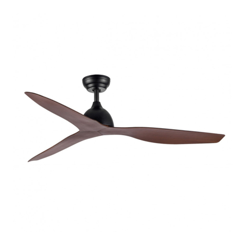
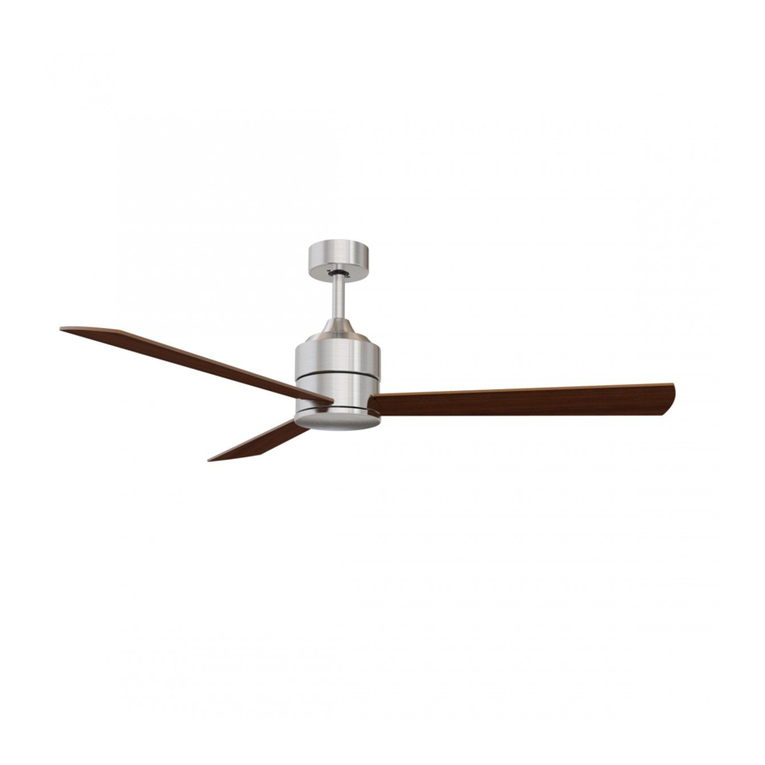
HOFFLIGHTS ZANZIBAR User manual

ZANZIBAR
MANUAL DE INSTALACIÓN
INSTALLATION MANUAL
MANUEL D’INSTALLATION
IMH-099 v.01


ÍNDICE INDEX INDEX
Manual de instalación ventilador 4
Instrucciones de uso del mando a distancia 11
Fan installation manual 14
Remote control user manual 21
Manuel d’installation du ventilateur 24
Mode d’emploi de la télécommande 31
PRECAUCIÓN
LEA LAS INSTRUCCIONES CON ATENCIÓN PARA GARANTIZAR UNA INSTALACIÓN
SEGURA Y UN BUEN FUNCIONAMIENTO DEL VENTILADOR.
EN CASO DE DUDA CONSULTE A UN ELECTRICISTA CERTIFICADO
CAUTION
READ INSTRUCTIONS CAREFULLY FOR SAFE INSTALLATION AND FAN OPERATION.
IF UNSURE CONSULT A QUALIFIED ELECTRICIAN.
PRECAUTION
LISEZ ATTENTIVEMENT LES INSTRUCTIONS POUR GARANTIR UNE INSTALLATION
SÉCURISÉE ET LE BON FONCTIONNEMENT DU VENTILATEUR.
EN CAS DE DOUTE CONSULTEZ UN ÉLECTRICIEN QUALIFIÉ

hofflights.com
4
MANUAL DE INSTALACIÓN
ZANZIBAR
IMH-099 v.01
Gracias por comprar este producto de calidad. Para asegurar su uso y la seguridad, por favor lea y conserve este manual
antes de utilizar el producto.
W
Motor V RPM
Airflow
(CFM) ØxH (mm.) Kg
5.0120.0222 26 100-240 190 4000 1320x305 5
5.0120.0211 26 100-240 190 4000 1320x305 5
WARRANTY
MOTOR
10
2,3
m
IP20
DC
MOTOR 5SPEED
SOLID
WOOD
BLADES
M
15-20
m2
GRACIAS POR SU COMPRA
SEGURIDAD
1. Para evitar posibles choques eléctricos, corte la luz desde la caja de fusibles o magnetotérmicos antes de empezar con
la instalación del ventilador, su puesta en marcha o la instalación de los accesorios.
2. Lea las instrucciones y los consejos de seguridad con atención antes de instalar el ventilador y conserve estas
instrucciones.
3. Asegúrese de que todas las conexiones son conformes con las normas locales y el código nacional eléctrico (NEC).
Si nunca ha hecho un montaje eléctrico, por favor consulte un electricista acreditado.
4. Asegúrese de seleccionar un sitio en el que su ventilador tenga un espacio despejado para la rotación de las aspas y al
menos 2,3 m (7,5 pies) de distancia entre el suelo y las extremidades de las aspas. El ventilador debe ser instalado a
por lo menos 75 cm (30 pulgadas) de las paredes y de otras estructuras verticales.
5. ADVERTENCIA: La caja eléctrica y el soporte de la vigueta de techo utilizados deben ser fijados y asegurados para
poder soportar al menos 45 kg. (100 libras). Para reducir el riesgo de choque eléctrico o de heridas, se debe montar la
caja eléctrica indicada como siendo compatible con un soporte de ventilador y se deben usar los tornillos proporciona-
dos en el cartón. La caja eléctrica debe instalarse directamente sobre la estructura del edificio.
6. ADVERTENCIA: Para reducir el riesgo de choque eléctrico o de heridas, se debe montar la caja eléctrica indicada
como siendo “compatible con un soporte de ventilador” y se deben usar los tornillos proporcionados en el cartón, la
mayoría de las cajas eléctricas que se usan habitualmente para el soporte de las luminarias no son compatibles para
un soporte de ventilador y han de ser sustituidas. Consulte a un electricista acreditado en caso de duda.
7. Una vez completada la instalación, controle que todas las conexiones sean seguras.
8. Una vez las conexiones eléctricas efectuadas, los conductores deben ser volteados y empujados con cuidado hacia
dentro de la caja eléctrica. Los cables deben ser apartados con el conductor de tierra y la toma de tierra del aparato
por un lado de la caja eléctrica.
9. ADVERTENCIA: Para reducir el riesgo de choque eléctrico o de fuego, no se debe utilizar este ventilador con un
mando fijo de pared o reostato.
10. No utilizar la función inversa hasta que el ventilador se haya parado completamente.
11. No insertar objetos en las aspas cuando el ventilador está funcionando.
12. ADVERTENCIA: Para reducir el riesgo de heridas no plegar los soportes de las aspas (también llamadas “bridas”)
durante el montaje o después de la instalación. No inserte objetos en el giro de las aspas.
13. Para evitar heridas o daños al ventilador o cualquier otro elemento, tenga cuidado al trabajar en esta zona o cuando
limpie el ventilador.
14. No use agua o detergente para limpiar el ventilador o las aspas. Un trapo seco o ligeramente humedecido será sufi-
ciente para su limpieza.
NOTA: Las importantes medidas e instrucciones de seguridad descritas en el manual no pretenden responder a todas las
situaciones posibles que puedan ocurrir. El sentido común y la prudencia son factores necesarios para la instalación y la
puesta en marcha de este ventilador.
NOTA: Este producto no debe ser usado por personas (incluyendo a niños) con capacidad física reducida, capacidades
sensoriales o mentales diferentes o reducidas, o con falta de experiencia o conocimiento, salvo si aquellas personas son
vigiladas o entrenadas para hacer funcionar el aparato por una persona responsable de su seguridad.
NOTA: Los niños deben ser vigilados para asegurarse de que no estén utilizando el ventilador como un juguete.
NOTA: Debe instalar un magnetotérmico o interruptor que desconecte todos los polos de potencia en al menos 3 mm entre
cada polo.

MANUAL DE INSTALACIÓN
ZANZIBAR
5hofflights.com IMH-099 v.01
Desenvuelva el ventilador y verifique el contenido de la caja. Debe encontrar lo siguiente:
1Soporte de fijación
2Tornillos de montaje
3Florón
4Tija & bola de suspensión
5Perno
6Acoplamiento
7Pin de bloqueo
8Bloque motor del ventilador
9Aspas
10 Tornillos para las aspas
11 Tornillos para madera
12 Tornillos de expansión
13 Arandelas
14 Kit de equilibrado
15 Kit de mando a distancia
8
9
10
1
2
3
4
5
15
11 12 13 14
6
7
RECEIVER
ANTES DE LA INSTALACIÓN

hofflights.com
6
MANUAL DE INSTALACIÓN
ZANZIBAR
IMH-099 v.01
Herramientas requeridas:
Destornillador Phillips, par de pinzas, destornillador de ranura, llave ajustable, escalera de mano y cortador de cables.
INSTALACIÓN DEL VENTILADOR
El ventilador de techo debe instalarse en un lugar que permita que las aspas estén a 12“ (300mm) de distancia desde la
punta de la aspa hasta el objeto o la pared más cercana. A la hora de colgar el ventilador NO OLVIDE cortar la corriente
eléctrica. Siga las instrucciones a continuación para colgar el ventilador correctamente:
INSTALACIÓN DEL SOPORTE DE FIJACIÓN
Para techos de hormigón, perfore dos
agujeros en el techo y asegure el soporte
de fijación con dos Φ0.32” (8mm) (la
distancia entre los dos agujeros ha de ser
la adecuada) tornillos de expansión, las
arandelas planas, los pernos proporcio-
nados y luego apretar con una llave.
1
Ver la ilustración a la derecha para la
instalación en un techo inclinado con un
ángulo de máx. 15 grados.
NOTA: una vez completada la instalación
el gancho debe poder soportar un peso
de 100lbs (45kg) o más.
3
2
Para techo de madera, asegurar el
soporte de fijación para que éste pueda
soportar un peso de al menos 100lbs
(45kg) con los dos tornillos largos y las
arandelas proporcionadas. Asegúrese de
que al menos 0.12”(30mm) del tornillo
está insertado dentro del soporte.
MONTAJE DE LAS ASPAS
Coloque el cuerpo motor encima del
poliestireno para instalar las aspas.
Alinee los agujeros de las aspas con los
agujeros del motor como en la ilustra-
ción, luego instale la aspa en el bloque
motor con los tornillos pre-montados.
Repita este procedimiento para las
demás aspas.
15°

MANUAL DE INSTALACIÓN
ZANZIBAR
7hofflights.com IMH-099 v.01
A la hora de colgar el ventilador NO OLVIDE cortar la corriente eléctrica. Siga las etapas a continuación para colgar el
ventilador adecuadamente:
5Alinee los agujeros en la parte de abajo de la tija con los agujeros del acoplamiento arriba de la caja eléctrica.
6Inserte con cuidado el perno dentro de los agujeros del acoplamiento y de la tija. Tenga cuidado de no enganchar el
perno con los cables del interior de la tija. Inserte el pin de bloqueo dentro del agujero cerca de la extremidad del
perno hasta que haga clic y quede en posición bloqueada.
7Inserte el pin de soporte en los agujeros en la parte de arriba de la tija. Asegúrese de que el pin del soporte esté
correctamente colocado en las ranuras en la parte de arriba de la bola de suspensión.
8Apriete firmemente el kit de tornillos.
9Apriete firmemente dos tornillos en la parte de arriba de la caja del ventilador.
MONTAJE DE LA TIJA
3El ventilador es entregado con dos opciones de
tijas 4” y 10” (10 cm y 25cm) Elija una tija que sea
adecuada para el techo e insértela dentro de la
bola de suspensión.
4Coloque los cables que salen de la parte superior
del motor del ventilador dentro del acoplamiento,
del florón y luego dentro de la tija y de la bola de
suspensión.
1Voltee el bloque motor para que las aspas queden
por encima.
2Retire los pernos, el pin de
bloqueo y los tornillos de
la tija.

hofflights.com
8
MANUAL DE INSTALACIÓN
ZANZIBAR
IMH-099 v.01
HACER LAS CONEXIONES ELÉCTRICAS
MONTAR EL VENTILADOR EN EL SOPORTE DE TECHO
UTILIZAR SU VENTILADOR
ADVERTENCIA: Para evitar posibles choques eléctricos,
asegúrese de que la corriente esté cortada desde la caja
de fusibles antes de hacer el cableado.
1. Inserte el receptor dentro del soporte de fijación con
la parte plana del receptor hacia el techo. Conexiones
eléctricas del motor con el receptor: Conecte los cables
del conector macho rosa/rojo/marrón del ventilador con
los cables hembra del receptor. Asegúrese de que todas
las conexiones estén seguras.
2. Conexiones eléctricas del receptor con la caja de cables:
Conecte el cable marrón del techo con el cable marrón
del receptor. Conecte el cable azul (neutro) del techo
con el cable azul del receptor. Asegure las conexiones
de los cables con las tuercas para cables proporcio-
nadas.
Motor
Receptor
Azul (Neutro)
Azul (N)
Marrón
(fase)
Rosa/rojo/marrón
conector (macho)
Marrón (L)
Amarillo/verde
(tierra)
Amarillo/verde
(tierra)
ADVERTENCIA: Para evitar posibles choques eléctricos,
asegúrese de que la corriente esté cortada desde la caja
de fusibles antes de hacer el cableado.
1. Instale la tija dentro de la bola de suspensión. Alinee
(coloque) la bola en la ranura con la pestaña del soporte
de fijación. Advertencia: Una mala alineación la bola en
la ranura con la pestaña puede provocar graves heridas.
2. Deslice el florón hacia el techo y alinee los agujeros
en el florón con los tornillos pre-montados del soporte
de suspensión. Gire en el sentido de las agujas del
reloj hasta que se bloquee. Apriete firmemente los dos
tornillos.
MANDO A DISTANCIA
Encienda y verifique el funcionamiento del ventilador
1Ventilador en posición ON/OFF
2Kit de luz en posición ON/OFF
3Velocidad del ventilador (1 baja – 5 alta)
4Sentido de rotación (modo invierno/verano)
5Temporizador del ventilador
1 2
4
5
3
FAN
3
F/R 42
1
1H 4H 8H
5
LIGHT
ON/OFF ON/OFF

MANUAL DE INSTALACIÓN
ZANZIBAR
9hofflights.com IMH-099 v.01
RESOLUCIÓN DE PROBLEMAS
1. Verifique todos los fusibles o magnetotérmicos. Sustituya los que falten.
2. Apague la corriente eléctrica y verifique todas las conexiones de los cables del ventilador y del interruptor.
1. Puede que el ventilador esté girando en sentido contrario por lo que el aire se va hacia arriba (modo invierno).
2. Puede que la habitación tenga elementos que obstruyen el flujo del aire.
3. Puede que el ventilador sea demasiado pequeño para la habitación.
1. Una oscilación leve es considerada como aceptable y no debería ser considerada como un defecto.
2. Asegúrese de que el soporte de fijación esté apretado a la caja de empalme/al techo y de que no se mueva en absoluto.
Apriete los tornillos de ser necesario.
3. Asegúrese de que todos los tornillos que retienen las aspas y el bloque motor estén apretados. Asegúrese de que los
tornillos de kit de luz/del cristal estén apretados.
4. Un movimiento leve es normal. Sin embargo, intercambiar un par de aspas adyacentes (lado a lado) puede repartir el
peso para obtener un mejor funcionamiento.
5. La mayoría de los problemas de oscilación son debidos al desnivel de las aspas.
Compruebe este nivel seleccionando un punto en el techo arriba de las aspas.
Mida la distancia como se muestra en la ilustración. La medidas siempre deben ser
entre 1/8” (2,5 cm/20,5 cm). Haga rotar el ventilador hasta que la próxima aspa esté
colocada a la medida. Repita lo mismo para cada aspa.
1. El uso de un reostato estándar o de un control de pared variable provocará siempre distorsiones armónicas o un
zumbido. Muchos motores de ventiladores no funcionan en silencio con un control de pared variable. Si desea utilizar
un control de pared silencioso, use únicamente los que sean certificados y de 3 velocidades.
2. Deje siempre unos días a su ventilador para que “se adapte” a velocidad mediana o alta. Intente identificar la proce-
dencia exacta del ruido escuchando atentamente desde diferentes ángulos (aspas, motor, kit de luz, etc.). El ruido del
ventilador puede proceder del kit de luz.
3. Asegúrese de que el soporte de fijación esté perfectamente enganchado a la caja de empalme.
4. Asegúrese de que las tuercas para cables de la caja eléctrica o del florón no se golpeen entre sí o contra la caja de
pared. Envuélvalos en cinta aislante de ser necesario.
5. Asegúrese de que el florón no esté tocando el techo.
6. Compruebe que los tornillos de las aspas al bloque motor estén apretados y que las arandelas previstas para tal
efecto hayan sido usadas.
EL VENTILADOR NO ARRANCA:
EL VENTILADOR GIRA PERO MUEVE POCO AIRE:
EL VENTILADOR TIEMBLA U OSCILA:
EL VENTILADOR HACE RUIDO:
Touching
ceiling

hofflights.com
10
MANUAL DE INSTALACIÓN
ZANZIBAR
IMH-099 v.01
1. Los movimientos naturales del ventilador pueden provocar conexiones sueltas. Un ruido de chasquido o de golpeteo
es una señal de que los tornillos se están soltando. Compruebe las conexiones del soporte, de las aspas dos veces al
año y apriételos según las necesidades.
2. Limpie su ventilador periódicamente. Use solo un trapo humidificado con un detergente suave. No utilice jamás sol-
vente. Quite el polvo con un trapo o una brocha. Los acabados del metales llevan un laqueado especial para prevenir
las manchas.
3. Nunca deberá engrasar su ventilador. Su rodamientos permanentemente sellados proporcionarán un funcionamiento
silencioso y sin fallo durante muchos años.
4. Asegúrese de que la corriente esté apagada desde la caja de fusibles o del magnetotérmico antes de hacer cualquier
reparación.
MANTENIMENTO

MANDO
A DISTANCIA
INSTRUCCIONES DE USO

MANDO
A DISTANCIA
hofflights.com12
INSTRUCCIONES DE USO
IMH-099 v.01
DIAGRAMA DEL CABLEADO DEL MANDO A DISTANCIA DIAGRAMA DE INSTALACION DEL RECEPTOR
MANUAL DEL RECEPTOR
Black
Light live-wire Power supply live-wire
Brown
Black wire
Blue
Light neutral-wire Power supply neutral-wire
Blue
Pink
To Motor wire Ground wire
Antenna wire
Yellow/Green
Grey
To Motor wire Red
To Motor wire
Receiver
V Ventilador Luz
220-240 40W máx 200W máx
Técnica de emisión digital RF inalámbrica, control biunívoco, el código de coincidencia es inferior a un millón de veces. (el
MANDO A DISTANCIA y el receptor deben enviarse a la fábrica para su reparación en caso de avería)
El receptor puede ser controlado desde cualquier ángulo con el MANDO A DISTANCIA en un espacio dado, hacia cualquier
dirección. Gracias a la funcionalidad de memoria el mando a distancia puede registrar la posición (luz y rotación) cuando
está apagado y volver a la posición original cuando se enciende.
1Ventilador en posición ON/OFF
2Luz en posición ON/OFF
3Velocidad del ventilador (1 baja - 5 alta)
4Sentido de rotación (modo invierno/verano)
5Temporizador
6Indicador LED
7Batería del emisor (12V, 23A) - No incluida
1 2
7
4
5
6
3
FAN
3
F/R 42
1
1H 4H 8H
5
LIGHT
ON/OFF ON/OFF

MANDO
A DISTANCIA INSTRUCCIONES DE USO
13hofflights.com IMH-099 v.01
RECORDATORIOS
1. El modo emparejamiento se utiliza entre el MANDO A DISTANCIA y el receptor. Pulse la tecla “ON” durante 30
segundos y a continuación pulse la tecla MANDO A DISTANCIA “VENTILADOR ON/OFF” durante 5 segundos, quedará
activado tras haber emitido un “bip” largo que significa un correcto emparejamiento y que puede ahora funcionar con
normalidad. (PS: el modo emparejamiento no es aceptado una vez que la corriente está en “ON” desde más de 30
segundos)
2. Si el emisor no controla el receptor, compruebe que el POLO de la batería está haciendo contacto, corrección del polo
positivo y negativo, batería llena o vacía.
3. Si el MANDO A DISTANCIA no controla el receptor, compruebe si existen mandos a distancia similares a poca distancia
y después compruebe si éstos funcionan, en efecto los aparatos que funcionan con un mando a distancia en la misma
frecuencia presentan interferencias.
4. Una batería de bajo voltaje puede afectar la sensibilidad del MANDO A DISTANCIA y la señal de recepción también (el
indicador se enciende cuando la batería alcanza un voltaje bajo), en tal caso hace falta sustituir la batería cuando ésta
llega a un nivel de voltaje bajo.
5. Retire la batería del MANDO A DISTANCIA cuando no la vaya a utilizar durante mucho tiempo.
6. Soporta una luz de 200W máximo.
7. PD: conecte correctamente el cableado del suelo, de lo contrario la luz puede empezar a parpadear o destellar
8. Durante la instalación del ventilador y especialmente de su soporte, no apriete la antena (o cualquier otro cable), esto
podría provocar cortes de luz o corto-circuitos.

hofflights.com14
INSTALLATION MANUAL
ZANZIBAR
IMH-099 v.01
Thank you for purchasing this quality product. To ensure correct function and safety, please read and save all instructions
before using the product.
1. To avoid possible electric shock, turn off the electricity at the main fuse box or circuit panel before you begin the fan
installation or before servicing the fan or installing accessories.
2. Read all instructions and safety information carefully before installing your fan and save these instructions.
3. Make sure all electrical connections comply with local codes or ordinances and the National Electrical Code. If you are
unfamiliar with electric wiring, please use a qualified and licensed electrician.
4. Make sure you have a location selected for your fan that allow clear space for the blades to rotate, and at least 7,5 feet of
clearance between the floor and the fan blade tips. The fan should be mounted at least 30 inches from walls or other
upright structures.
5. WARNING: The outlet box and ceiling support joist used must be securely mounted, and capable of supporting at least
100 pounds. To reduce the risk of fire, electric shock or personal injury, mount to the outlet box marked acceptable
for fan supported and use mounting screws provided with the outlet box. The box must be supported directly by the
building structure.
6. WARNING: To reduce the risk of fire, electric shock or personal injury, mount to outlet box marked “acceptable for fan
support” and use mounting screws provided with the outlet box most outlet boxes commonly used for the support of
lighting fixtures are not acceptable for fan support and may need to be replaced. Consult a qualified electrician if in
doubt.
7. After installation is complete, check that all connections are absolutely secure.
8. After making electrical connections, spliced conductors should be turned upward and pushed carefully up into outlet
box. The wires should be spread apart with the grounded conductor and the equipment-grounding conductor on one
side of the outlet box.
9. WARNING: To reduce the risk of electrical shock and fire, do not use this fan with any solid-state fan speed control
device, or rheostat.
10. Do not separate the reverse switch until the fan has come to a complete stop.
11. Do not insert anything into the fan blades while they are rotating.
12. WARNING: To reduce the risk of personal injury, do not bend the blade brackets (also referred to as “flanges”) during
assembly or after installation. Do not insert objects in the path of the blades.
13. To avoid personal injury or damage to the fan and other items, be cautious when working around or cleaning the fan.
14. Do not use water or detergent when cleaning the fan or fan blades. A dry dust cloth or lightly dampened cloth will be
suitable for most cleaning.
NOTE: The important safety precautions and instructions appearing in the manual are not meant to cover all possible
conditions and situations that may occur. It must be understood that common sense and caution are necessary factors in
the installation and operation of this fan.
NOTE: This product is not intended for use by persons (including children) with reduced physical, sensory or mental capa-
bilities are different or are impaired, or lack of experience or knowledge, unless such persons are supervised or trained to
operate the appliance by a person responsible for their safety.
NOTE: Children should be supervised to ensure that they do not use appliances as a toy.
NOTE: You must install a switch or circuit breaker that disconnects all poles power of at least 3mm between each pole.
W
Motor V RPM
Airflow
(CFM) ØxH (mm.) Kg
5.0120.0222 26 100-240 190 4000 1320x305 5
5.0120.0211 26 100-240 190 4000 1320x305 5
WARRANTY
MOTOR
10
2,3
m
IP20
DC
MOTOR 5SPEED
SOLID
WOOD
BLADES
M
15-20
m2
THANK YOU FOR YOUR PURCHASE
SAFETY TIPS

INSTALLATION MANUAL
ZANZIBAR
15hofflights.com IMH-099 v.01
Unpack your fan and check the contents.You should have the following:
1Mounting bracket
2Mounting screws
3Canopy
4Downrod& hanger ball
5Bolt
6Coupling cover
7Lock pin
8Fan motor assembly
9Blades
10 Screws for blades
11 Wood screws
12 Expansion screws
13 Screw washers
14 Balancing kit
15 Remote control set
BEFORE INSTALLATION
8
9
10
1
2
3
4
5
15
11 12 13 14
6
7
RECEIVER

hofflights.com16
INSTALLATION MANUAL
ZANZIBAR
IMH-099 v.01
Tools Required:
Phillips screwdriver, Pair of pliers, straight slot screwdriver, adjustable wrench, step ladder, and wire cutters.
INSTALLING THE FAN
The ceiling fan must be installed in a location so that the blades are 12“ (300mm) spacing from the tip of the blade to the
nearest objects or walls. When hanging the fan REMEMBER to turn off the power. Follow the instruction below to hang
your fan properly:
INSTALLING THE MOUNTING BRACKET
INSTALL THE BLADES
2
For wood ceiling, Secure the
mounting bracket to the ceiling is
capable of carrying a load of at least
100lbs (45kg) with two long mounting
screws and washers provided. Be
sure at least 0.12”(30mm) of the
screw is threaded into the support.
For concrete ceiling, drill two
holes in the ceiling and secure the
mounting bracket to the ceiling with
two Φ0.32” (8mm)(distance between
the two holes should be appropriate)
expansion screws, flat washers,nuts
provided and tighten with a spanner.
1
Refer to the Fig. in right for mounting
when the ceiling is angled max. 15
degree angle.
NOTE: Hanger after the installation
must be able to withstand the weight
of 100lbs (45kg) or more
3
15°
Place motor assembly on bottom
Styrofoam for blades installation.
Aligning the holes on bladeand
the screw holes on motor as
shown in illustration, and then
install the blade to the motor with
preassembled screws. Repeat this
process for remaining blades.

INSTALLATION MANUAL
ZANZIBAR
17hofflights.com IMH-099 v.01
When hanging the Fan REMEMBER to turn off the power. Follow the steps below to hang your fan properly:
5Align the holes at the bottom of the downrod with the holes in the coupling on top of the top housing
6Carefully insert the Bolt through the holes in the Coupling and downrod. Be careful not to jam the Bolt against the
wiring inside the downrod. Insert the locking pin through the hole near the end of the Bolt until it snaps into its locked
position
7Insert the support pin in the holes at the top of the downrod. Make sure the support pin is properly seated in the
grooves in the top of the hanger ball
8Tighten the set crews firmly
9Tighten two set screws on top of the fan housing firmly
INSTALL THE DOWNROD
3Your fan comes with two optional downrods 4” and
10” (10cm and 25cm)Choose one downrod which is
suitable for your ceiling and slide the hanger ball
up the downrod
4Route wires exiting from the top of the fan motor
through thecoupling cover, canopy and then through
the downrod and the hanger ball.
1Flip the motor assembly with blades over. 2Remove the bolt,
lock pin and set screws
from the downrod

hofflights.com18
INSTALLATION MANUAL
ZANZIBAR
IMH-099 v.01
MAKE THE ELECTRIC CONNECTIONS
INSTALLING THE FAN TO MOUNTING BRACKET ON CEILING
USING YOUR CEILING FAN
WARNING: To avoid possible electrical shock, be sure
electricity is turned off at the main fuse box before wiring.
1. Insert the receiver into the mounting bracket with the flat
side of the receiver facing the ceiling. Motor to Receiver
Electrical Connections: Connect the Pink/red/brown
wire male plug from the fan to the corresponding female
terminal on the receiver. Make sure all connections are
secured
2. Receiver to House supply wires Electrical Connections:
Connect the Brown(hot) wire from the ceiling to the
Brown wire from the receiver. Connect the Blue(neutral)
wire from the ceiling to the Blue wire from the Receiver.
Secure the wire connections with the wire nuts provided.
WARNING: To avoid possible electrical shock, be sure
electricity is turned off at the main fuse box before wiring.
1. Install ball end of downrod into mounting bracket
opening. Align (engage) slot on ball with tab on mounting
bracket. Warning: Failure to align slot on ball with tab
may result in serious injury.
2. Slide the canopy up to ceiling andalign the keyhole slots
on the canopy with the preassembled screws on the
hanger bracket. Twist clockwise until it locks. Tighten
the two screws securely.
REMOTE CONTROL
Turn on the power and check the operation of the fan
1ON/OFF the fan
2ON/OFF the light
3Speed of the fan (1 low speed - 5 high speed)
4Direction of the fan (summer/winter mode)
5Timing control of the fan
Supply circuit
Receiver
Blue (Neutral)
Blue (N)
Brown
(phase)
Pink/red/brown
plug (male)
Brown (L)
Yellow/green
(ground)
Yellow/green
(ground)
1 2
4
5
3
FAN
3
F/R 42
1
1H 4H 8H
5
LIGHT
ON/OFF ON/OFF

INSTALLATION MANUAL
ZANZIBAR
19hofflights.com IMH-099 v.01
TROUBLE SHOOTING
1. Check all fuses or circuit breakers. Replace if missing.
2. Turn off electrical power and check all wire connections to fan and in switch housing.
1. The fan may be running in reverse, so air is directed upward (winter mode).
2. The room may contain items that obstruct the air flow.
3. The fan may be too small for size of the room.
1. Use of standard light rheostat or continuously variable fan speed wall control will always cause harmonic distortions,
or a humming noise. Many fan motors do not work quietly with solid state variable controls. If a quiet wall control in
desired, use only 3-speed approved wall controls.
2. Always allow a few days “break in” time for any new fan at medium or high speed. Try to diagnose the exact location of
the noise by listening carefully from several sides (blades, motor, light kits, etc.). Fan noise can come from a light kit.
3. Make sure mounting bracket is installed snugly to junction box.
4. Make sure wire nuts in switch housing or canopy are not rattling against each other or against wall of housing. Wrap
with electrical tape if necessary.
5. Make sure the canopy is not touching the ceiling.
6. Assure that the screws fastening blade arm to motor are tight and the lock washers provided for that purpose have
been used.
FAN WILL NOT START:
FAN TURNS BUT DOES NOT MOVE MUCH AIR:
FAN SHAKES OR WOBBLES:
FAN IS NOISY:
1. A small amount of movement is considered acceptable and should not be considered a defect.
2. Make sure mounting bracket is tight at junction box/ceiling with no movement at all. Tighten screws if necessary.
3. Make sure all screws holding the blades to the blade arm and blade arm to motor are tight. Make sure light kit/glass
screws are tight.
4. Some fan movement is normal. However, interchanging and adjacent (side-by-side) blade pair may redistribute the
weight and result in smooth operation.
5. Most fan wobble problems are caused when blade levels are unequal. Check this
level by selecting a point on the ceiling above the tip of one of the blades. Measure
this distance as shown in picture. Measurements should always be within 1/8”. Rotate
the fan until the next blade is positioned for measurement. Repeat for each blade.
Touching
ceiling

hofflights.com20
INSTALLATION MANUAL
ZANZIBAR
IMH-099 v.01
1. The fan’s natural movements may cause some connections to work loose. A clicking or rattling noise is a certain sign
of loosening screws. Check the support connections, brackets and blade attachments twice a year, and tighten all
screws as necessary.
2. Clean your fan periodically. Use only a cloth dampened with a mild detergent solution. Never use solvents. Dust with a
soft cloth or brush. Metal finishes are finished with a lacquer to prevent tarnishing.
3. You will never need to oil your fan. Its permanently sealed bearings will provide silent, trouble free operation for many
years.
4. Make sure the power is turned off at the main fuse or circuit panel before you attempt any repairs.
MAINTENANCE
This manual suits for next models
2
Table of contents
Languages:
Other HOFFLIGHTS Fan manuals
Popular Fan manuals by other brands

Zehnder Rittling
Zehnder Rittling ComfoAir XL QuickGuide Installation

enervent
enervent Alta eWind installation instructions

CIAT
CIAT MAJOR 300 CV User brochure

Emerson
Emerson DC BUILDER ES Series owner's manual

Modern Forms
Modern Forms NIRVANA FR-W1916-56L installation instructions

Midea
Midea MSVI-40 owner's manual