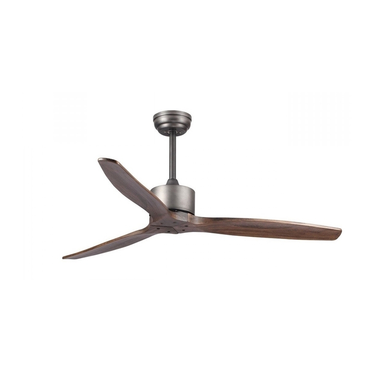
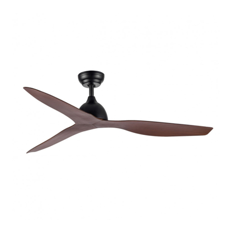
HOFFLIGHTS POLYNESIA User manual

POLYNESIA
MANUAL DE INSTALACIÓN
INSTALLATION MANUAL
MANUEL D’INSTALLATION
IMH-101 v.01


ÍNDICE INDEX INDEX
Manual de instalación ventilador 4
Instrucciones de uso del mando a distancia 11
Fan installation manual 14
Remote control user manual 21
Manuel d’installation de ventilateur 24
Mode d’emploi de la télécommande 31
PRECAUCIÓN
LEA LAS INSTRUCCIONES CON ATENCIÓN PARA GARANTIZAR UNA INSTALACIÓN
SEGURA Y UN BUEN FUNCIONAMIENTO DEL VENTILADOR.
EN CASO DE DUDA CONSULTE A UN ELECTRICISTA CERTIFICADO
CAUTION
READ INSTRUCTIONS CAREFULLY FOR SAFE INSTALLATION AND FAN OPERATION.
IF UNSURE CONSULT A QUALIFIED ELECTRICIAN.
PRECAUTION
LISEZ ATTENTIVEMENT LES INSTRUCTIONS POUR GARANTIR UNE INSTALLATION
SÉCURISÉE ET LE BON FONCTIONNEMENT DU VENTILATEUR.
EN CAS DE DOUTE CONSULTEZ UN ÉLECTRICIEN QUALIFIÉ

hofflights.com
4
MANUAL DE INSTALACIÓN
POLYNESIA
IMH-101 v.01
Gracias por comprar el modelo de ventilador con la mayor eficiencia energética. Este ventilador funciona con un motor DC
(corriente continua) que permite ofrecer una gran eficiencia en el ahorro de energía manteniendo un volumen importante
de desplazamiento del aire y un funcionamiento silencioso.
Ahorro de energía - El motor DC es la última tecnología en los diseños de ventiladores. Su motor altamente eficiente
ahorra hasta un 65% más de energía que los ventiladores tradicionales con un motor AC.
Funcionamiento silencioso - Este ventilador con motor DC está programado con la corriente estabilizada que reduce
eficientemente el ruido del motor.
Funcionamiento a temperatura baja - La corriente DC es eficiente lo cual permite bajar la temperatura de funcionamiento
del motor a menos de 50°. Esto permite tener un motor mucho más frío que el de un ventilador AC y aumenta el tiempo
de vida del motor.
Mando a distancia con 6 velocidades. Los ventiladores clásicos con motos AC en general tienen 3 velocidades, este venti-
lador DC ofrece 6 velocidades, lo cual permite mayores opciones y nivel de confort.
GRACIAS POR SU COMPRA
PRECAUCIONES IMPORTANTES
LEA ATENTAMENTE ESTAS INSTRUCCIONES ANTES DE INSTALAR O USAR ESTE PRODUCTO.
MANTENGA LAS INSTRUCCIONES A MANO PARA CONSULTAS MÁS ADELANTE.
IMPORTANTE: Utilice siempre el producto en una toma de corriente del mismo voltaje, frecuencia y potencia.
IMPORTANTE: La estructura sobre la cual se debe montar el ventilador debe poder soportar un peso de 40 kg.
IMPORTANTE: El ventilador debe ser instalado de manera que las aspas queden al menos a 2,3 m (7,5 pies) del suelo.
“Este producto no debe ser usado por personas (incluyendo a niños) con capacidad física reducida, capacidades sensoria-
les o mentales diferentes o reducidas, o con falta de experiencia o conocimiento, salvo si aquellas personas son vigiladas
por una persona responsable de su seguridad”.
“Los niños deben ser vigilados para asegurarse de que no estén utilizando el ventilador como un juguete”.
No utilice este producto si le parece o ha sido dañado o si muestra defectos.
PRECAUCIÓN:
1. Un dispositivo de desconexión de todos los polos debe ser integrado al cableado conforme a las reglas de cableado.
ADVERTENCIA: PARA UN USO SEGURO DE ESTE VENTILADOR SE DEBE AÑADIR UN DISPOSITIVO DE DESCONEXIÓN EN
EL CABLEADO CONFORME A LAS REGLAS DE CABLEADO.
2. No tire aparatos eléctricos con la basura común municipal, utilice los puntos de reciclaje adaptados. Contacte su
ayuntamiento para obtener información sobre los sistemas de recolección disponibles. Cuando aparatos eléctricos
son tirados en el campo o vertederos, sustancias peligrosas pueden derramarse en los suelos y llegar a la cadena
alimenticia, dañando nuestra salud y nuestro bienestar.
3. Este ventilador es para uso interior únicamente. Es peligroso instalar el ventilador en un lugar en el que puede ser
expuesto al agua o la humedad.
4. Solo un electricista habilitado puede efectuar la instalación.
DC
MOTOR 6SPEED
PLY
WOOD
BLADES
M
15-20
m2
2,3
m
IP20 WARRANTY
MOTOR
10
3K
4K
5K7
DIMMING
W
Motor V RPM
Airflow
(CFM) ØxH (mm.) Kg
5.0110.2211 38 220-240 200 5041 1320x387 5,1
5.0110.2222 38 220-240 200 5041 1320x387 5,1
Accesorios
W
LED K CRI ØxH (mm.) Kg
5.0100.8111 Módulo LED 18 3K-4K-5K7 >90 180x25 0,5
5.0100.8112 Módulo LED 18 3K-4K-5K7 >90 180x25 0,5

MANUAL DE INSTALACIÓN
POLYNESIA
5hofflights.com IMH-101 v.01
1Soporte de fijación (x1)
2Florón (x1)
3Tija (x1)
4Cubierta (x1)
5Bloque motor (x1)
6Kit de luz LED (x1)
(a comprar por separado)
7Tapa inferior (x1)
8Aspas (x3)
9Sistema de control (x1 kit)
(emisor + mando a distancia)
10 Tacos de plástico (x2)
Tornillos de aspas (x10)
Compresores de aspas (x3)
Tornillos de madera (x2)
Tornillos de expansión (x2)
Kit de equilibrado (x1 kit)
Desenvuelva el ventilador y verifique el contenido de la caja. Debe encontrar lo siguiente:
ANTES DE LA INSTALACIÓN
La instalación del ventilador debe ser conforme a las normas y reglas establecidas por las autoridades locales. Un electri-
cista cualificado y profesional debe encargarse de la instalación. Unos medios de desconexión deben ser incorporados al
cableado conforme a las reglas de cableado.
El ventilador y la luz deben ser conectados a la tierra. El soporte debe ser firmemente sujeto a una estructura sólida.
Por ejemplo un techo de hormigón, una estructura metálica o un marco de madera, etc. y debe ser fijado entre las vigas
en caso de ser necesario. No utilizar otro mando a distancia para controlar el ventilador, esto anularía la garantía del
producto.
El uso de mando a distancia no autorizadas anula la garantía. NO MEZCLE las aspas con las de otro ventilador. Todas las
aspas deben ser reemplazadas en caso de estar dañadas. El interruptor de pared incluido es un conmutador único.
Abra el embalaje con cuidado. Retire las piezas del porexpan.
Saque la caja del motor y colóquelo en una alfombra o en un porexpan para evitar dañar los acabados. No tire el cartón ni
el porexpan en caso de tener que devolver el ventilador para su reparación. Compruebe que todas las piezas del inventario
están presentes.
SEGURIDAD
ADVERTENCIA
DESENVUELVA EL VENTILADOR
10
6
7
3
5
18
9
2
4

hofflights.com
6
MANUAL DE INSTALACIÓN
POLYNESIA
IMH-101 v.01
Herramientas requeridas:
Destornillador Phillips, destornillador de aspas, llave de 10mm, escalera de mano y cortador de cables.
Apague los magnetotérmicos desde la caja de fusibles y asegúrese de que el interruptor de la luz esté en posición OFF.
ADVERTENCIA: Una desconexión errónea antes de la instalación puede provocar heridas graves.
INSTALACIÓN DEL VENTILADOR
PREPARACIÓN DE LA INSTALACIÓN
2
Este ventilador puede ser montado con una tija en un techo estándar (sin
pendiente) o ligeramente inclinado. Otras instalaciones, como un soporte
empotrado, no son disponibles para este ventilador.
Para evitar heridas y daños, asegú-
rese de que el sitio de colocación
permita que las aspas estén a una
distancia mínima de 2,3 m (7,5 pies)
y a 0,76 m (2,5 pies) de las paredes
o muebles de alrededor.
1
Instalación de la tija Montaje de techo
instalación
El ángulo de inclinación
del techo no debe
exceder los 15°
2,3 m
0,76 m
aspa
INSTALACIÓN DEL SOPORTE DE FIJACIÓN
2
Para techo de madera, asegurar el
soporte de fijación para que éste pueda
soportar un peso de al menos 45kg
(100lbs) con los dos tornillos largos y las
arandelas proporcionadas. Asegúrese de
que al menos 30mm (0.12”) del tornillo
está insertado dentro del soporte.
Para techos de hormigón, perfore dos
agujeros en el techo y asegure el soporte
de fijación con dos Φ8mm (0.32”) (la
distancia entre los dos agujeros ha de ser
la adecuada) tornillos de expansión, las
arandelas planas, los pernos proporcio-
nados y luego apretar con una llave.
1

MANUAL DE INSTALACIÓN
POLYNESIA
7hofflights.com IMH-101 v.01
A la hora de colgar el ventilador NO OLVIDE cortar la corriente eléctrica. Siga las etapas a continuación para colgar el
ventilador adecuadamente:
MONTAJE DE LA TIJA
1
2
Coloque el bloque motor en el poliestireno para
instalar las aspas.
Retire la bola de suspensión de la tija proporciona-
da aflojando los tornillos de la bola de suspensión.
Retire el pin y el clip. Baje la bola de suspensión y
retire el pin de bloqueo. Deslice la bola de suspen-
sión sobre al tija
3
6
Afloje los tornillos del soporte del bloque motor.
Coloque los cables dentro de un extremo de la tija y
empuje el exceso de cables hacia arriba. Coloque
la tija dentro del soporte del bloque motor hasta
que los agujeros del pin y del clip de la tija estén
alineados con el soporte (asegúrese de que los ca-
bles no estén pinchados). Coloque de nuevo el pin
y el clip movidos previamente. Apriete firmemente
los tornillos del soporte del bloque motor.
Deslice la tija dentro del soporte de fijación y deje
que la bola de suspensión cuelgue del soporte de
fijación.
Gire la bola de suspensión hasta que las ranuras
encajen con las del soporte.
Pin de bloqueo
Kit de tornillos
Bola de
suspensión
PinClip
Cableado
Clip Pin
Tornillos soporte
bloque motor
Tija
4
Deslice la tapa de
el florón y el florón
sobre la tija.
Tija
Florón
Cubierta
Bloque motor
5Coloque los cables dentro de la bola de suspen-
sión; luego deslice la bola de suspensión sobre la
tija; utilice este agujero para poner los tornillos.
Inserte el pin de bloqueo en la parte superior de la
tija y levante la bola. Asegúrese de que se quede
insertado en las ranuras dentro de la bola de sus-
pensión. Apriete firmemente los tornillos.
Pin de bloqueo Kit de tornillos
Bola de
suspensión
Ranura soporte de
fijacion
Ranura bola de
suspensión
Bloque motor

hofflights.com
8
MANUAL DE INSTALACIÓN
POLYNESIA
IMH-101 v.01
Asegúrese de que la conexión esté hecha correctamente. En caso de duda, consulte un técnico.
220-240V
Casa Ventilador
2 PIN
azul / negro
3 PIN
gris / rojo / rosa
3 PIN
marrón / azul / amarillo-verde
1PIN
de la Tija
amarillo-verde
1PIN
del soporte de fijación
amarillo-verde
1
2
3
4
CABLEADO

MANUAL DE INSTALACIÓN
POLYNESIA
9hofflights.com IMH-101 v.01
MONTAJE DE EL FLORÓN
MONTAJE DE LAS ASPAS
MONTAJE SIN KIT DE LUZ MONTAJE DEL KIT DE LUZ
Fije 2 tornillos en la parte baja del eje y
afloje los dos tornillos.
Levante el florón en la suspensión.
Coloque las esquinas redondeadas
del agujero con ranuras en el florón y
empuje hacia arriba sobre los tornillos
desatornillados de la suspensión.
Gire el florón hasta su bloqueo. Luego
apriete firmemente los tornillos.
Inserte un lado de la aspa en el agujero
de montaje hacia el agujero alargado
del lado principal del motor.
Luego utilice el tornillo apara apretar el
compresor de aspa sobre la aspa.
Nota: Apriete los tornillos de las aspas
dos veces al año.
Identifique las ranuras en la tapa metálica para ali-
nearlas con los nódulos de la placa del motor. Empuje
despacio la tapa de metal y gire hacia la DERECHA (en
el sentido de la agujas de un reloj) hasta que se coloque
completamente en su sitio.
Si quiere utilizar un kit de luz, debe comprarlo por
separado.
Conecte el cable de la caja del motor al cable del kit de
luz LED. Asegúrese de que la conexión rápida se haga
completamente. Sitúe las ranuras del kit de luz LED
y alinee con los nódulos dentro de la placa del motor.
Empuje despacio el kit de luz LED y gírelo hacia la
DERECHA (en el sentido de las agujas del reloj) hasta
que quede totalmente colocado en su sitio.
Tornillo Tornillo
Soporte
de fijación
Florón
Bloque
motor
Compresor del aspa
Tornillo del aspa
Cubierta
motor
Tapa
metálica Nódulos
Ranuras
Cubierta
motor
Tapa metálica Nódulos
Ranuras
Conexión rápida

hofflights.com
10
MANUAL DE INSTALACIÓN
POLYNESIA
IMH-101 v.01
1. Los movimientos naturales del ventilador pueden provocar conexiones sueltas. Un ruido de chasquido o de golpeteo
es una señal de que los tornillos se están soltando. Compruebe las conexiones del soporte, de las aspas dos veces al
año y apriételos según las necesidades.
2. Limpie su ventilador periódicamente. Utilice solo un cepillo suave o un paño sin pelusa para evitar dañar los aca-
bados. La placa está sellada con laca para minimizar la decoloración o la pérdida de brillo. No utilice agua para la
limpieza. Esto podría dañar el motor, la madera, o probablemente causar un choque eléctrico
3. Puede aplicar una ligera capa de cera para muebles para pulir la madera de las aspas para una protección adicional y
mejorar su aspecto. Cubra todas las rayas con una ligera capa de betún para zapatos.
4. No hace falta engrasar su ventilador. El motor está constantemente lubricado por un sistema de rodamientos de bola
sellados.
• Este producto tiene una garantía limitada a 10 años para defectos en el motor.
• 2 año de garantía para defectos de fabricación y piezas.
• El controlador tiene una garantía de 2 años.
• El módulo LED tiene una garantía de 2 años.
MANTENIMENTO
GARANTÍA
RESOLUCIÓN DE PROBLEMAS
ADVERTENCIA: Una desconexión errónea de la corriente principal antes de hacer una reparación de cableado puede
ocasionar graves heridas.
1. Compruebe la conexión del interruptor.
2. Compruebe que el cableado del ventilador esté correcto.
3. Compruebe la batería.
1. Compruebe la conexión del interruptor.
2. Compruebe que el cableado de el florón esté correcto.
3. Compruebe que el conector rápido del kit de luz esté correctamente conectado.
EL VENTILADOR NO ARRANCA:
EL KIT DE LUZ NO SE ENCIENDE:

MANDO
A DISTANCIA
INSTRUCCIONES DE USO

MANDO
A DISTANCIA
hofflights.com12
INSTRUCCIONES DE USO
IMH-101 v.01
DIAGRAMA DEL CABLEADO DEL MANDO A DISTANCIA DIAGRAMA DE INSTALACION DEL RECEPTOR
MANUAL DEL EMISOR
Receptor
V Ventilador Luz
220-240 40W máx 140W máx
Técnica de emisión digital RF inalámbrica, control biunívoco, el código de coincidencia es inferior a un millón de veces.
(El MANDO A DISTANCIA y el receptor deben enviarse a la fábrica para su reparación en caso de avería)
El receptor puede ser controlado desde cualquier ángulo con el MANDO A DISTANCIA, hacia cualquier dirección. Gracias
a la funcionalidad de memoria el mando a distancia puede registrar el estado (luz y sentido de rotación) cuando está
apagado y volver a la posición original cuando se enciende.
1Ventilador en posición ON/OFF
2Sentido de rotación (modo invierno/verano)
3Velocidad del ventilador (1 baja - 6 alta)
4Viento natural
5Temporizador
6Anti-robo
7Disminuir intensidad de la luz
8Aumentar intensidad de la luz
9Luz en posición ON
10 Luz en posición OFF
11 Batería (1,5V AAA x 2 unidades) - No incluida
1
5
7
9
2
4
3
8
10
11
6
Negro
Light live-wire Power supply live-wire
Marrón
Negro
Azul
Light neutral-wire Power supply neutral-wire
Azul
Rosa
To Motor wire Ground wire
Antenna wire
Amari/Verde
Gris
To Motor wire Rojo
To Motor wire
RECEPTOR

MANDO
A DISTANCIA INSTRUCCIONES DE USO
13hofflights.com IMH-101 v.01
EMPAREJAMIENTO DE 2 A 5 VENTILADORES
RECORDATORIOS
El modo emparejamiento se utiliza entre el mando a distancia y el receptor.
Encienda la linea eléctrica de los ventiladores que quiera sincronizar y espere unos 30 segundos hasta escuchar el primer
“bip”. A continuación mantenga la tecla “ON/OFF” pulsada durante 5 segundos hasta escuchar un “bip” largo que significa
un correcto emparejamiento.
Si el emparejamiento no ha funcionado, debe volver a apagar y encender la linea eléctrica de los ventiladores.
Con un mando a distancia se pueden controlar hasta 5 ventiladores.
1. Si el mando a distancia no controla al receptor, compruebe que las baterías estén bien colocadas y que tengan carga.
2. Si el mando a distancia no controla el receptor, compruebe si existen mandos a distancia similares a poca distancia
y después compruebe si éstos funcionan, es posible que los aparatos que funcionan con un mando a distancia en la
misma frecuencia presentan interferencias.
3. Una batería agotada puede afectar la sensibilidad del mando a distancia y la señal de recepción también (el indicador
se enciende cuando la batería alcanza una carga baja), en tal caso hay que sustituir la batería.
4. Retire la batería del mando a distancia cuando no la vaya a utilizar durante mucho tiempo.
5. Soporta una luz de 140W máximo.
6. PD: conecte correctamente el cable de tierra, de lo contrario la luz puede empezar a parpadear o destellar.
7. Durante la instalación del ventilador y especialmente de su soporte, no apriete la antena (o cualquier otro cable), esto
podría provocar cortes de luz o corto-circuitos.

hofflights.com14
INSTALLATION MANUAL
IMH-101 v.01
POLYNESIA
Thank you for purchasing the latest in energy saving ceiling fans. This fan runs on DC (direct current) power which gives it
the benefit of being super energy efficientwhilst still maintaining high volume air-movement and silent operation.
Energy saving- The DC motor is the latest technology in fan design. Its highly efficient motor saves up to 65% more energy
than ceiling fans with traditional Acmo-tors.
Silent operation-This DC fan motor is programmed with a stabilized current whichefficiently reduces motor noise.
Low operating temperature-The DC power is managed effectively which bringsdown the motor operating temperature to
less than 50degs. This results in a muchcooler motor than a standard AC fan and increases the longevity of the motor.
6 speed remote control. Regular AC ceiling fans usually come with only 3 speeds, this DC fan comes complete with a 6
speed remote, which gives greater choice of comfort levels.
THANK YOU FOR YOUR PURCHASE
IMPORTANT SAFEGUARDS
READ THESE INSTRUCTIONS CAREFULLY BEFORE INSTALLING OR USING THE PRODUCT.
KEEP THE INS-TRUCTIONS HANDY FOR FUTURE REFERENCE.
IMPORTANT: Always operate the product from a power source of the same Voltage, frequency and rating.
IMPORTANT: The structure to which the fan is to be mounted must be capable of supporting weight of 40kg.
IMPORTANT: The fan should be mounted so that the blades are at least 7 feet above the floor.
“This appliance is not intended for use by persons (including children) with reduced physical, sensory or mental capabi-
lities, or lack of experience or knowledge, unless they have been given supervision or instruction concerning use of the
appliance by a person responsible for their safety.”
“Young children should be supervised at all times to ensure that they do not play with the appliance.
Do not operate any product which has been or appears damaged in any matter or after the product malfunctions.
CAUTION:
1. An all-pole disconnection switch must be incorporated in the fixed wiring in accordance with the wiring rules.
WARNING: FOR SAFE USE OF THIS FAN AN ALL POLE DISCONNECTION MUST BE INCORPORATED INTO THE FIXED
WIRING IN ACCORDANCE WITH THE WIRING RULES.
2. Do not dispose of electrical appliances as unsorted municipal waste, use separate collection facilities. Contact your
local government for information regarding the collection systems available. If electrical appliances are disposed of
in landfills ordumps, hazardous substances can leak into the groundwater and get into the foodchain, damaging your
health and well-bein.
3. This fan is suitable for indoor use only. Mounting the fan in a situation where it is subject to water or moisture is
dangerous.
4. Only an authorized electrician should execute the installation.
DC
MOTOR 6SPEED
PLY
WOOD
BLADES
M
15-20
m2
2,3
m
IP20 WARRANTY
MOTOR
10
3K
4K
5K7
DIMMING
W
Motor V RPM
Airflow
(CFM) ØxH (mm.) Kg
5.0110.2211 38 220-240 200 5041 1320x387 5,1
5.0110.2222 38 220-240 200 5041 1320x387 5,1
Accessories
W
LED K CRI ØxH (mm.) Kg
5.0100.8111 LED Module 18 3K-4K-5K7 >90 180x25 0,5
5.0100.8112 LED Module 18 3K-4K-5K7 >90 180x25 0,5

INSTALLATION MANUAL
15hofflights.com IMH-101 v.01
POLYNESIA
1Hanging bracket (x1)
2Canopy (x1)
3Downrod (x1)
4Coupling cover (x1)
5Motor housing assembly (x1)
6LED light kit (x1)
(need to purchase separately)
7Bottom cover (x1)
8Blades (x3)
9Control system (x1 set)
10 Plastic anchors (x2)
Blades screws (x10)
Blades tablettings (x3)
Wood screws (x2)
Expansion screws (x2)
Balance kit (x1 set)
Unpack your fan and check the contents. You should have the following:
BEFORE INSTALLATION
Installation of fans must follow regional standards and meet local Authorith regulations. A fully qualified and licensed
electrician lawfully MUST carry out installation. Means for disconnection must be incorporated in the fixed wiring in accor-
dance with wiring rules. Fan and light MUST be earthed. Bracket MUST be firmly attached to a solid structure i.e. concrete
ceiling, steel structure or timber frame, etc. and MUST be nailed between beams if the timber option is required. DO NOT
control operation of fan and light with any other remote control, as this will void warranty.
The use of unauthorised controllers will void the warranty. DO NOT mix blades from one fan to another. All blades must be
replaced if damaged wall switch included is a single pole switch.
Carefully open the packaging. Remove items from Styrofoam inserts.
Remove motor housing and place on carpet or Styrofoam to avoid damage to finish. Do not discard fan carton or Styrofoam
inserts should this fan need to be returned for repairs. Check against parts inventory that all parts have been included.
SAFETY
WARNING
UNPACKING YOUR FAN
10
6
7
3
5
18
9
2
4

hofflights.com16
INSTALLATION MANUAL
IMH-101 v.01
POLYNESIA
Tools Required:
Phillips screwdriver, Blade screwdriver, 10 mm wrench, step ladder, and wire cutters.
INSTALLING THE FAN
INSTALLATION PREPARATION
2
This fan can be mounted with a downrod on a regular (no-slope) or vaulted
ceiling. Other installation,such as flushmount, is not available for this fan.
To prevent personal injury and da-
mage, ensure that the hanging loca-
tion allows the blades a clearance
of 7.5 feet from the floor and 2.5
feet from any wall or obstruction.
1
Downrod installation Roof mount
installation
Vaulted ceiling angle
is not to exceed
15 degrees
7.5 feet
2.5
feet
blade
HANGING BRACKET INSTALLATION
Turn off circuit breakers to current fixture from breaker panel and be sure operating light switch is turned to the OFF
position. WARNING: Failure to disconnect power supply prior to installation may result in serious injury.
2
For wood ceiling, Secure the mounting
bracket to the ceiling is capable of carr-
ying a load of at least 100lbs (45kg) with
two long mounting screws and washers
provided. Be sure at least 0.12”(30mm) of
the screw is threaded into the support.
For concrete ceiling, drill two holes in the
ceiling and secure the mounting bracket
to the ceiling with two Φ0.32” (8mm)
(distance between the two holes should
be appropriate) expansion screws, flat
washers,nuts provided and tighten with
a spanner.
1

INSTALLATION MANUAL
17hofflights.com IMH-101 v.01
POLYNESIA
When hanging the Fan REMEMBER to turn off the power. Follow the steps below to hang your fan properly:
INSTALL THE DOWNROD
1
2
Place motor assembly on bottom Styrofoam for
blades installation.
Remove hanging ball from downrod provided by
loosening set screw on hanging ball. Remove pin
and clip. Lower hanging ball and remove stop pin.
Slide hanging ball off of the downrod.
3
6
Loosen yoke set screws at top of motor housing.
Thread electrical wires through threaded end of
downrod and pull extra wire slack from the upper
end of the downrod. Thread downrod into the motor
housing yoke until holes for pin and clip in downrod
align with holes in yoke, make sure wires do not
get twisted. Re-insertpin and clip that were pre-
viously removed. Tighten yoke set screws securely
Slide downrod through opening in hanging bracket
and let hanging ball rest on the hanging bracket.
Turn the hanging ball slot until it lines up with the
hanging bracket tab.
Stop pin
Set screw
Hanging
ball
PinClip
Wiring
Clip Pin
Yoke set screw
Downrod
4
Slide yoke cover
and canopy over
downrod
Downrod
Canopy
Yoke cover
Motor housing
5Thread wires through hanging ball; then slide han-
ging ball over downrod; use this hole when setting
the set screw. Insert stop pin into top of downrod
and raise hanging ball. Be sure stoppin aligns with
slots on the inside of the hanging ball. Tighten set
screw securely
Stop pin Set screw
Hanging
ball
Hanging bracket tab
Hanging ball slot
Motor housing

hofflights.com18
INSTALLATION MANUAL
IMH-101 v.01
POLYNESIA
Be sure that the connection is made properly. If in doubt consult a technician
220-240V
Home Fan
2 PIN
blue / black
3 PIN
grey / red / pink
3 PIN
brown / blue / yellow-green
1PIN
from downrod
yellow-green
1PIN
from hanging bracket
yellow-green
1
2
3
4
WIRING

INSTALLATION MANUAL
19hofflights.com IMH-101 v.01
POLYNESIA
CANOPY ASSEMBLY
BLADE ASSEMBLY
ASSEMBLY WITHOUT LIGHT KIT LIGHT KIT ASSEMBLY
Fix the 2 screws on the bottom of the
boom and loosen the two screws. Hoist
the canopy onto the hanger. Place the
rounded corner of the slotted hole in the
canopy push upward over loose screws
on the hanger. Rotate canopy lock. Then
tighten screw safe.
Insert one side of the blade mounting
hole into the direction of the long strip
hole on the main side of the motor. Then
use the blade screw to tighten the blade
pressure plate with the blade.
Note: Tighten blade screws twice a year.
Locate slots on metal cover and align with nodules on
inside of motor plate. Gently push up on metal cover
and turn to the RIGHT (clockwise) until it slides comple-
tely into place
If you wish to use the light kit, please purchase light
kit separately.
Connect wire from motor housing to wire from the LED
light kit. Make sure quick connection snap together
completely. Locate slots on LED light kit and align with
nodules on inside of motor plate. Gently push up on
LED light kit and turn to the RIGHT(clockwise) until it
slides completely into place.
Screw Screw
Hanging
bracket
Canopy
Motor
housing
Blade tablettings
Blade screw
Motor
housing
Motor
plate Nodules
Slots
Motor
housing
Motor plate Nodules
Slots
Quick connection

hofflights.com20
INSTALLATION MANUAL
IMH-101 v.01
POLYNESIA
TROUBLE SHOOTING
WARNING: Failure to disconnect power supply prior to troubleshooting any wiring issues may result in serious injury.
• This product carries a limited 25 year warranty against defects in the motor.
• 1 year warranty against defects in workmanship and materials.
• The controller is guaranteed for 2 years.
• LED warranty for 2 years.
WARRANTY
1. Check power to switch control.
2. Check to be sure fan is wired properly.
3. Check the battery is good or not.
1. Check power to switch control.
2. Check that wires in canopy are wired properly.
3. Verify that quick connection connected properly in LED light kit.
FAN FAILS TO OPERATE:
LIGHT KIT NOT LIGHTING:
1. Because of the fan’s natural movement, someconnections may become loose. Check the support connections, brac-
kets, and blade attachments twice a year. Make sure they are secure. (It is not necessary to remove fan from ceiling.)
2. Clean your fan periodically to help maintain its new appearance over the years. Use only a soft brush or lint-free cloth
to avoid scratching the finish. The plating is sealed with a lacquer to minimize discolouration or tarnishing. Do not use
water when cleaning. This could damage the motor, the wood, or possibly cause an electric shock.
3. You can apply a light coat of furniture polish to the wood blades for additional protection and enhanced beauty. Cover
small scratches with a light application of shoe polish.
4. There is no need to oil your fan. The motor has permanently lub ricated sealed ball bearings.
MAINTENANCE
This manual suits for next models
2
Table of contents
Languages:
Other HOFFLIGHTS Fan manuals