HOKUYO AUTOMATIC UXM-30LAH-EWA User manual

Title
Approved by
Checked by
Designed by
Symbol Amended Reason Date Amended by
DWG.NO
/
5
Drawn by
C-4 -02495
Date: 20 4.5.27
Area Designer
Instruction Manual
Drawing
No.
Kristou
KristouKristou
Kristou
Fukuda
FukudaFukuda
Fukuda
Aoki
AokiAoki
Aoki
Aoki
AokiAoki
Aoki
Area Designer
UXM-30LAH-EWA configuration tool
Instruction manual

Title
Drawing
NO
Area Designer
Instruction Manual
C
-
4
-
02495
2/5
[Introduction]
Make sure to read this manual before and during operation for the correct operation.
[About Area Designer]
By using this application, it is possible to monitor the sensor and area configuration. Also, it is
possible to save measurement data and area data.
[Before use]
Make sure to read the specification of the sensor before operation.
[Precautions]
• Make sure to perform operations with a stable power supply listed in the product specifications
and the user’s manual. Operating under unstable power supply may damage the device.
• The actual product may differ from the illustrations and figures in this document as they are
used for explanatory purposes only.
• All information in this user’s manual is subject to change without prior notice.
• If you have any inquiry about the product, contact the nearest distributor or sales representative.

Title
Drawing
NO
Area Designer
Instruction Manual
C
-
4
-
02495
3/5
Table of contents
. System requirments ................................................................................................................................4
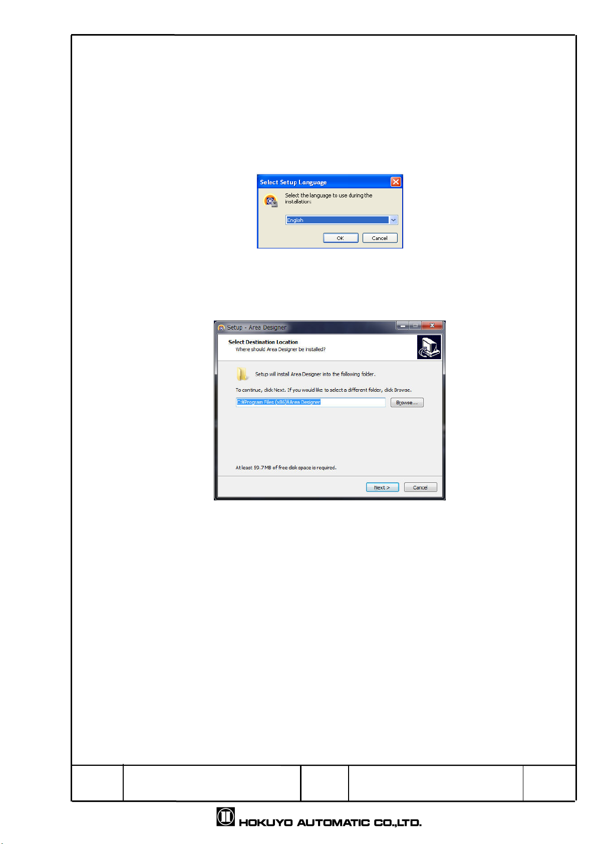
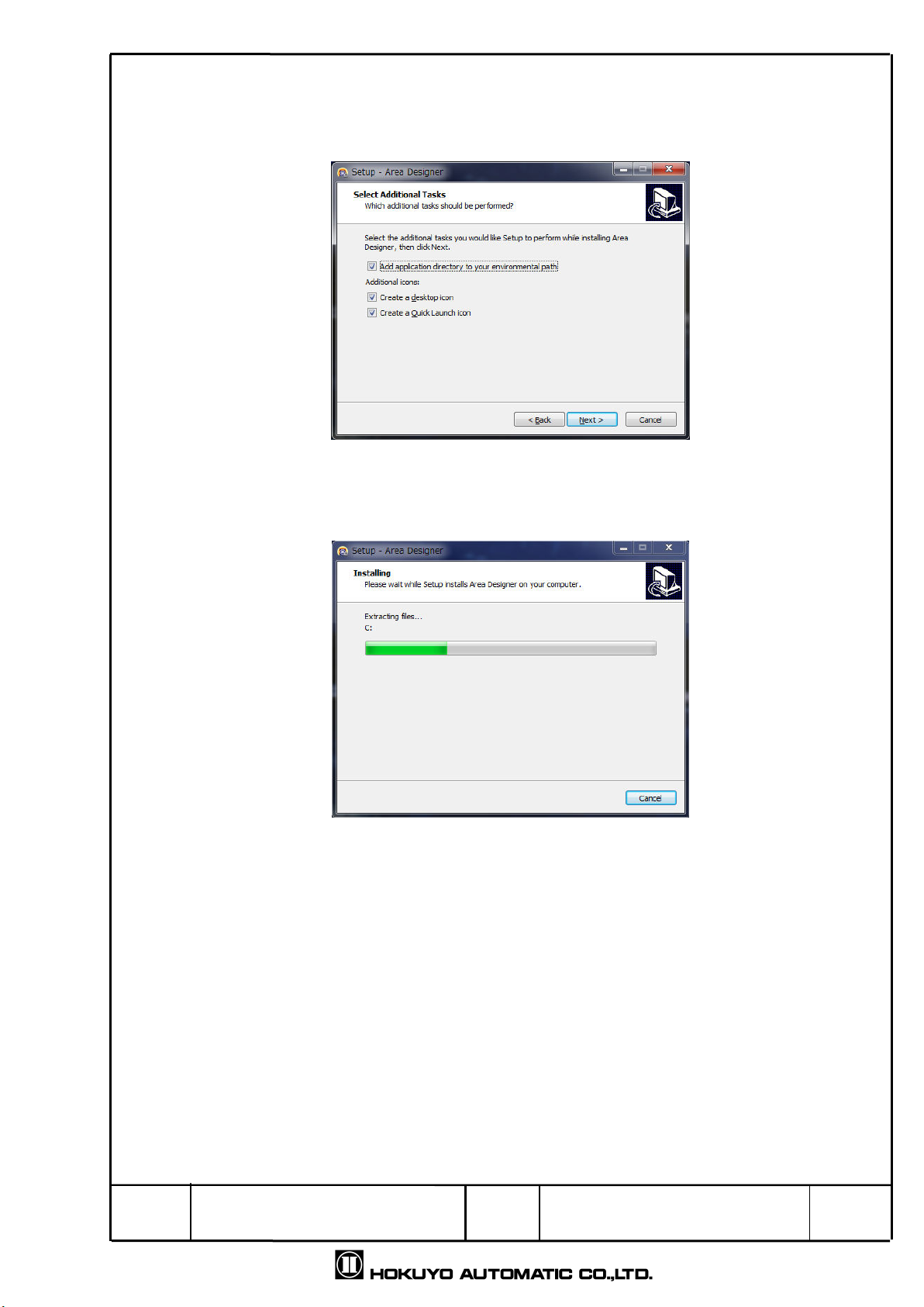
2. Installing the application..........................................................................................................................5
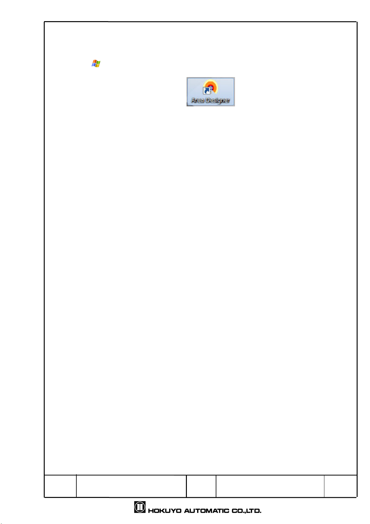
3. Using the application...............................................................................................................................8
4. Main window screen ..............................................................................................................................9
4. Welcome to Area Designer screen...........................................................................................9
4.2 Main screen ............................................................................................................................
4.2. Edit .....................................................................................................................................
4.2.2 Monitor.................................................................................................................................30
4.3 Data table................................................................................................................................3
4.4 Sensor setting .........................................................................................................................33
4.5 IO simulation ...........................................................................................................................35
4.6 Sensor information..................................................................................................................38
4.7 Log data ..................................................................................................................................39
4.8 Playing log data ......................................................................................................................40
4.9 About the application ..............................................................................................................4
5. Function of main window screen ........................................................................................................42
5. . Menu bar.................................................................................................................................42
5. . File.......................................................................................................................................42
5. .2 Edit ......................................................................................................................................43
5. .3 View.....................................................................................................................................44
5. .4 Connections ........................................................................................................................45
5. .5 Language ............................................................................................................................46
5. .6 Help .....................................................................................................................................46
5.2. Toolbar ....................................................................................................................................47
5.2. Basic tool.............................................................................................................................47
5.2.2 Connection tool ...................................................................................................................48
5.2.3 Mode selection tool .............................................................................................................48
5.2.4 Measurement display tool ...................................................................................................48
5.3. Main view toolbar ....................................................................................................................49
5.4. Status bar ................................................................................................................................49
Appendix A Network address....................................................................................................................5
Appendix B Troubleshooting.....................................................................................................................5

Title
Drawing
NO
Area Designer
Instruction Manual
C
-
4
-
02495
4/5
. System Requirement
The minimum system requirement for the operation of Area Designer is as follows.
After reading the operation manual of computer, check the operating environment.
CPU Pentium® III processor of 800MHz or above
RAM 256MB or above
Computer
Hard disk 00MB minimum free space
Microsoft® Windows XP Professional 32bit (SP3 or above)
Microsoft® Windows 7 Professional
Compatible
OS Microsoft® Windows 8
Display High color ( 6bit color)or above, 800×600 dot or above
The operation in the below system environment cannot be guaranteed.
Other OS that is not mentioned above
NEC PC98 series and its compatible device
Self made PC
Multi boot environment
Multi monitor environment
Upgraded OS from the standard installed OS
□ Operation is not guaranteed even if the minimum system requirements are fulfilled.
Caution

Title
Drawing
NO
Area Designer
Instruction Manual
C
-
4
-
02495
5/5
2. Installing the application
In this section it will explain how to install application in Windows. Refer to Appendix A for
network address set up.
. This application can be downloaded from our company’s website. In order to install this
application, double click the installer “Area Designer”.
2. Double click the installer “Area Designer” and the following screen will be displayed.
Here the language can be changed at the time of installation.
Fig 2- Select the language for an installer
3. As shown in Fig 2. click “ok” then it displays the screen of the installation location of Area
Designer. If there is no particular specification then, click “next”.
Fig 2-2 Specify the location for an installation

Title
Drawing
NO
Area Designer
Instruction Manual
C
-
4
-
02495
6/5
4. As shown in Fig 2.2 click “next”, then select the component of “Area Designer”.
If there is no particular specification then click “next”.
Fig 2-3 Select the component
5. As shown in Fig 2-3, click “next” then user will be proceed to specify the program group of
“Area Designer”. If there is no particular specification then click “next”.
Fig 2-4 Specify the program group

Title
Drawing
NO
Area Designer
Instruction Manual
C
-
4
-
02495
7/5
6. Once you click next as shown in Fig 2-4 then, proceed to additional task select screen.
After selecting the additional tasks you would like for this setup to perform while installing,
then click next.
Fig 2-5 Select additional tasks
7. As shown in Fig 2-5, click next then, installation of “Area Designer” will start.
Fig 2-6 Installation in progress

Title
Drawing
NO
Area Designer
Instruction Manual
C
-
4
-
02495
8/5
3. Using the application
. Power supply to the sensor. Connect Ethernet cable with computer.
2. Click Start menu → All programs →Area Designer. Or Double click Area Designer
shortcut icon as shown on the desktop below Fig 3. .
Fig 3. Area Designer icon
3. Starts the Area Designer application.

Title
Drawing
NO
Area Designer
Instruction Manual
C
-
4
-
02495
9/5
4. Main window screen
When the application is started, this will explain the main window screen displayed.
4. Welcome to “Area Designer” screen
If application starts, the following window will be displayed as shown in Fig. 4. - .
Table 4. - explains details of three buttons of this window.
Fig 4. - Welcome to “Area Designer” screen
Table 4. - Button of “Welcome to Area Designer” screen
Button Description
Create a new project file.
Open an existing project file.
Connect with the sensor.

Title
Drawing
NO
Area Designer
Instruction Manual
C
-
4
-
02495
0/5
In table 4. -3 Details of the components will be explained as below.
Fig 4. -2 Serial connection component
Table 4. -3 Serial connection component
Icon Name Description
Serial COM
Port
The connected COM port number will be
displayed. When using multiple sensors, select
the COM port which you want to connect.
Rescan
Rescan of serial port will be performed and the
number of connected COM port will be displayed
again.
Select
Baud rate
value
Select the baud rate value of RS422 when
connected.
Connect Connects with COM port and starts
communication.
Disconnect
Disconnect the communication.
Fig 4. -3 Ethernet connection component
Table 4. -4 Ethernet connection component
Icon Name Description
Input IP
address
Input IP address which you want to connect. The
port number is fixed.
Connect Connects with the IP address and starts
communication.
Disconnect
Disconnect the communication.

Title
Drawing
NO
Area Designer
Instruction Manual
C
-
4
-
02495
/5
4.2 Main screen
This is the main window used for area configuration and monitoring. Edit screen and
monitor screen can be switched by view →mode [ /edit] and [ /monitor] of the menu
bar. Click the or icon from the toolbar for switching the mode. The main screen
window of edit mode and monitor mode will be different.
4.2. Edit
In this screen, write area configurations to the sensor. Beside that, user can read the
area configurations from the sensor and display the area configuration from sensor.
Fig 4.2. - Default status in edit mode
Edit/Monitor wi
tch

Title
Drawing
NO
Area Designer
Instruction Manual
C
-
4
-
02495
2/5
As shown in Fig 4.2. -2 , icons of no. are used for undo or redo operations of
the icon no.2 through 6. As shown in the Fig. 4.2. -2 icon no.2 through 4 are used for
area configurations and operations. “Areas” refers to the regions configured with a
maximum of 3 outputs displayed on the main view of no. 6 as shown in Fig 4.2. -2.
The regions displayed in yellow, orange and red on the main view represent each
individual output region. As shown in Fig.4.2. -2 No.5 and No.6 are used for the area
configurations and operations of each output region.
Fig 4.2. -2 Edit tool of edit screen
1
2
3
5
4
6
Output region 1
Output region 2
Output region 3

Title
Drawing
NO
Area Designer
Instruction Manual
C
-
4
-
02495
3/5
4.2. . Area
In this the setting and operation of the present configured area is shown.
Copy, paste or read and write of the selected area can be performed.
4.2. . . Copy, Cut, Paste, Delete
As shown in Fig 4.2. . . [Copy] , [Cut] , [Paste] , [Delete] .
When you want to paste data of under configuration area to another area, [Copy]
and [Cut] are used. [Copy] on the left the data of selected area and paste in another
area. [Cut] deletes the data of selected area and pastes it in another area.
[Delete] eliminates the data of the selected area.
.
Fig 4.2. . . Copy, Cut, Paste, Delete
□ Copy, Cut, Paste and Delete tools cannot be used for each output region. Also,
these tools can be only used for each individual area; they cannot be used for
multiple areas.
4.2. . .2 Area preview
In Fig.4.2. -2 the functions of number 2 and 3 are used for the area preview.
When the background of the area number selected in the area preview turns blue,
that area can be edited. The area that can be edited will be displayed on the main
view illustrated in Fig.4.2. -2. The top left number in the area preview is the area
number. When changing area configuration, the editing mode of the selected area
in the area preview will turn to green and area is changed will be displayed in a tool
tip.
Fig 4.2. . .2- Left: Area preview of default status,
Right: Area preview of edit status
Caution

Title
Drawing
NO
Area Designer
Instruction Manual
C
-
4
-
02495
4/5
By right clicking in the area preview, the background of the selected area will
change to blue and display the sub menu as illustrated in Fig. 4.2. . .2-2. Functions
listed in this sub menu can be used for the area selected.
Fig 4.2. . .2-2 Menu displayed by the right click of Area preview
□ Area configuration is not possible in area 0, as laser is OFF.
□ The menu function can be used only for selected area. It is not possible for
multiple areas.
4.2. . .3 ON/ OFF delay
As shown in Fig 4.2. . .3 ON/OFF delay can be configured for each area. The
configurable range of ON/OFF delay setting is 50 to 6400(ms) and width is 50(ms).
Fig 4.2. . .3 ON / OFF delay setting
Cautions

Title
Drawing
NO
Area Designer
Instruction Manual
C
-
4
-
02495
5/5
4.2. .2 Regions
As shown in Fig 4.2. .2, Output to 3 is displayed when selecting the tabs, or
click on any of outputs as displayed in yellow, orange, and red on the main view. Then
it is possible to edit the selected outputs.
Fig 4.2. .2 Tab of output regions to 3
□ When deleting the point of an area, select the point which you want to delete then right
click the mouse. The Backspace or delete key can be used for deleting the point.
□ In the case when you want to make an adjustment to point position, hold the Ctrl Key
and move the mouse so the point moves in 0 (mm) intervals. And, if you hold the Shift
Key and move the mouse the point then moves in 00(mm) intervals. Also, if you hold
the Ctrl Key and Shift Key move the mouse the point then moves in 000(mm)
intervals.
Quick/Useful tips

Title
Drawing
NO
Area Designer
Instruction Manual
C
-
4
-
02495
6/5
4.2. .2. Independent
In this section, it explains how to configure the output of an independent shape.
There are the 3 types: polygon, arc and rectangle. When one of these
independent shapes is selected, the point will be added to the center point of the
main view (refer to Fig. 4.2. .2. ). By moving this point, a region of the selected
shape can be configured.
Fig 4.2. .2. Default state during independent shape selection
When configuring an independent shape, there is a region where outputs can
be configured as well as a region where outputs cannot be configured. The
regions where an output can be configured are referred to as configurable region.
The regions where outputs cannot be configured are referred to as an
un-configurable region. As shown in Fig.4.2. .2. the configurable area region is
in white while the un-configurable area region is in gray.

Title
Drawing
NO
Area Designer
Instruction Manual
C
-
4
-
02495
7/5
4.2. .2. . Polygon
Polygons can be used as a configured area if the intended shape of the
output cannot configure as arc or rectangle. The information shown with a
polygon configuration will display the numbers of points configured and X and
Y coordinates of each point in the main view window. As shown in
Fig.4.2. .2. . here is an example of polygon configuration.
Fig 4.2. .2. . - Example of polygon configuration
When a point is deleted, the output will be configured to form a straight line
between one point to another depending on the one removed. If one is the center
point, then the output will be configured such that one point it forms a straight line
with the center point. When all the points are deleted other than the center point,
the entire output region will be deleted.

Title
Drawing
NO
Area Designer
Instruction Manual
C
-
4
-
02495
8/5
□ Maximum 30 points can be configured with a polygon.
□ When an area is configured with more than 3 points, first write the area into the sensor
and then read the area from the sensor, as shown in Fig. 4.2. .2. . -3; the points will be
displayed in all steps within the configured area. Although it is possible to write an area
with more than 3 points to configure into the sensor, the writing of point information on
the area cannot be guaranteed. In the event an area with more than 3 points, the
maximum number of points that can be displayed in the main view is the maximum
number of steps of the sensor + point.
Fig 4.2. .2. . -2 Left: Example of 30 points or less within the area
Right: Display an area of 30 points or less when read from the sensor
Fig 4.2. .2. . -3 Left: Example of more than 3 points within the area
Right: Display an area of more than 3 points when read from the sensor
Caution

Title
Drawing
NO
Area Designer
Instruction Manual
C
-
4
-
02495
9/5
4.2. .2. .2 Arc
When configuring arc, the point information is shown below.
Fig. 4.2. .2-6 consists of 2 output points.
Fig 4.2. .2. .2 Example of Arc configuration
The point information of an arc shape consists of the 2 angles to each point
from the starting angle of 0° on the main view and saves the information of the
radius of arc. The output area of an arc shape is configured from these 2 angles
and the radius of the arc. When the radius of one point is changed, the radius of
other point is also changed of same value. If either of one point is deleted, the
other point and the output region will be also deleted.

Title
Drawing
NO
Area Designer
Instruction Manual
C
-
4
-
02495
20/5
4.2. .2. .3 Rectangle
The output of a rectangle is configured of 4 points as illustrated in Fig.
4.2. .2. .3.
Fig 4.2. .2. .3- Example of rectangle configuration
The point information of a rectangle consists of last selected point and the
opposite 2 points of selected points. Based on the relative values between these
2 points, the horizontal and vertical lengths of the rectangle are calculated. The
output of a rectangle is then configured and that does not include the unavailable
region.
When any one of the 4 points is moved, the coordinates of other opposite
points will be changed. Points will change as drawing the rectangle’s 4 points and
it doesn’t include the unavailable region. When any one point of the rectangle is
deleted, the other points and the output region will also be deleted.
It is only possible to move a point to the unavailable region while configuring a
rectangle (refer to Fig. 4.2. .2. .3-2 for moving point in the unavailable region).
The configured output is a region enclosed within the 4 points and that does not
include the unavailable region.
Fig 4.2. .2. .3-2 when configuration of rectangle points moves to unavailable region
Other manuals for UXM-30LAH-EWA
1
Table of contents
Other HOKUYO AUTOMATIC Tools manuals
Popular Tools manuals by other brands

Rosenberger
Rosenberger HSD Series Assembly instruction

Matco Tools
Matco Tools BRK4TA Operating instructions, warning information, parts breakdown

Sealey
Sealey VS8621 instructions

Ingersoll-Rand
Ingersoll-Rand 324 Series Product information

Polar Fire
Polar Fire B33Z08 Assembly instructions & parts diagrams

Hitachi
Hitachi BRD-E2-30K Operation manual