Cerrowire ReelRover Training manual

1
4
©2020 Cerrowire Rev 03/2020
A Marmon/Berkshire Hathaway Company

2
Contents of the User Manual & Operating Instructions specify the manner in which the
ReelRover™is to be operated as intended by Cerrowire®. The ReelRover is designated for use
only as stipulated within this document. Any deviation from the User Manual & Operating
Instructions is unauthorized and represents improper use of the equipment. This designated
document is used by Cerrowire to conduct training of distribution customers for proper use so that
the ReelRover is safely and correctly operated in both the distribution facility and on the job site.
Cerrowire provides the User Manual & Operating Instructions document to distribution customers
so that subsequent internal training as well as external contractor training may be provided by the
distributor. It is the responsibility of the distributor to ensure that all internal and external users are
properly trained and qualified in accordance with the procedures presented in this manual.

3
Contents
Figures ..........................................................................................................................................4
Components ................................................................................................................................. 5
Specifications ............................................................................................................................... 6
Safety Procedures ........................................................................................................................ 7
Symbols and Warnings .................................................................................................................8
Gearbox ..................................................................................................................................... 10
PARK (P) ........................................................................................................................ 11
NEUTRAL (N) ................................................................................................................. 11
DRIVE (D) ....................................................................................................................... 11
Basic Operation .......................................................................................................................... 12
Operating the ReelRover in PARK ............................................................................................. 12
Operating the ReelRover in NEUTRAL ...................................................................................... 12
Steering in NEUTRAL .................................................................................................................12
Operating the ReelRover in DRIVE ............................................................................................ 13
Steering in DRIVE ...................................................................................................................... 14
Operating the ReelRover in DRIVE on a Ramp or Grade .......................................................... 15
Ground Reel ............................................................................................................................... 16
Ground Reel Lock Procedure ..................................................................................................... 17
Ground Reel Unlock Procedure ..................................................................................................18
Winding Adaptor ......................................................................................................................... 19
Winding Device Use with ReelRover ..........................................................................................20
Setting Gearbox ......................................................................................................................... 21
Wire Unloading (Payout) ............................................................................................................ 21
Transportation & Shipping .......................................................................................................... 22
Using a Liftgate to Load the ReelRover .......................................................................... 23
Using a Liftgate to Unload the ReelRover .......................................................................24
ReelRover Lock-out Procedure .................................................................................................. 25
Troubleshooting ..........................................................................................................................26
Equipment Inspection Prior to Use.............................................................................................. 27
Equipment Inspection Checklist ................................................................................................. 28

4
Figures
Figure 1a: ReelRover Components ..................................................................................................... 5
Figure 1b: Reel Components .............................................................................................................. 5
Figure 2a: ReelRover Specifications Side View .................................................................................. 6
Figure 2b: ReelRover Specifications Aerial View ................................................................................ 6
Figure 3: Gearbox Settings ................................................................................................................10
Figure 4: PARK Gearshift Position .................................................................................................... 11
Figure 5: NEUTRAL Gearshift Position ............................................................................................. 11
Figure 6: DRIVE Gearshift Position ................................................................................................... 11
Figure 7a: Sharp Turn in NEUTRAL .................................................................................................. 12
Figure 7b: Gradual Turn in NEUTRAL ...............................................................................................12
Figure 8: Reel and Drive Wheel Rotation .......................................................................................... 13
Figure 9a: Sharp Turn in DRIVE ........................................................................................................14
Figure 9b: Gradual Turn in DRIVE .....................................................................................................14
Figure 10a: Never Stand or Walk Downgrade of ReelRover ............................................................. 15
Figure 10b: Caster Wheels Should Always Be Downgrade ...............................................................15
Figure 11a: Reel Lock ........................................................................................................................16
Figure 11b: Reel Lock Indicator .........................................................................................................16
Figure 11c: Reel Unlock Indicator ......................................................................................................16
Figure 12: Reel Lock Procedure ........................................................................................................ 17
Figure 13: Reel Unlock Procedure .....................................................................................................18
Figure 14: Winding Adaptor Insertion ................................................................................................ 19
Figure 15: Winding Device Centerline Location .................................................................................19
Figure 16a: Winding Device Use with ReelRover Winding Adaptor Aerial View and Detail .............. 20
Figure 16b: Winding Device Use with ReelRover Winding Adaptor .................................................. 20
Figure 17a: NEUTRAL Gearshift Position ......................................................................................... 21
Figure 17b: PARK Gearshift Position ................................................................................................ 21
Figure 18: Wire Unloading ................................................................................................................. 21
Figure 19: Forklift Locations .............................................................................................................. 22
Figure 20a: Moving ReelRover onto Liftgate ..................................................................................... 23
Figure 20b: Remove Locking Pin ...................................................................................................... 23
Figure 20c: Insert Locking Pin ........................................................................................................... 23
Figure 20d: Moving ReelRover into Truck ......................................................................................... 23
Figure 21a: Moving ReelRover off Truck onto Liftgate ...................................................................... 24
Figure 21b: Remove Locking Pin ...................................................................................................... 24
Figure 21c: Insert Locking Pin ........................................................................................................... 24
Figure 21d: Moving ReelRover Off Liftgate ....................................................................................... 24
Figure 22a: Wire Cable Through Eyebolt .......................................................................................... 25
Figure 22b: Wire Cable Through Eyebolt .......................................................................................... 25
Figure 22c: Safety Cable Around Hand Rail of Reel ......................................................................... 25
Figure 22d: Lock the Two Ends of the Wire Cable Together with the Lock ...................................... 25
Figure 23: Left-Hand 180° Driven Turn ............................................................................................. 29
Figure 24: Right-Hand 180° Driven Turn ........................................................................................... 30
5
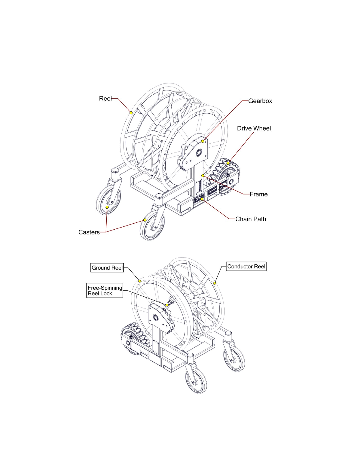
Components
Figure 1a: ReelRover Components
Figure 1b: Reel Components
6
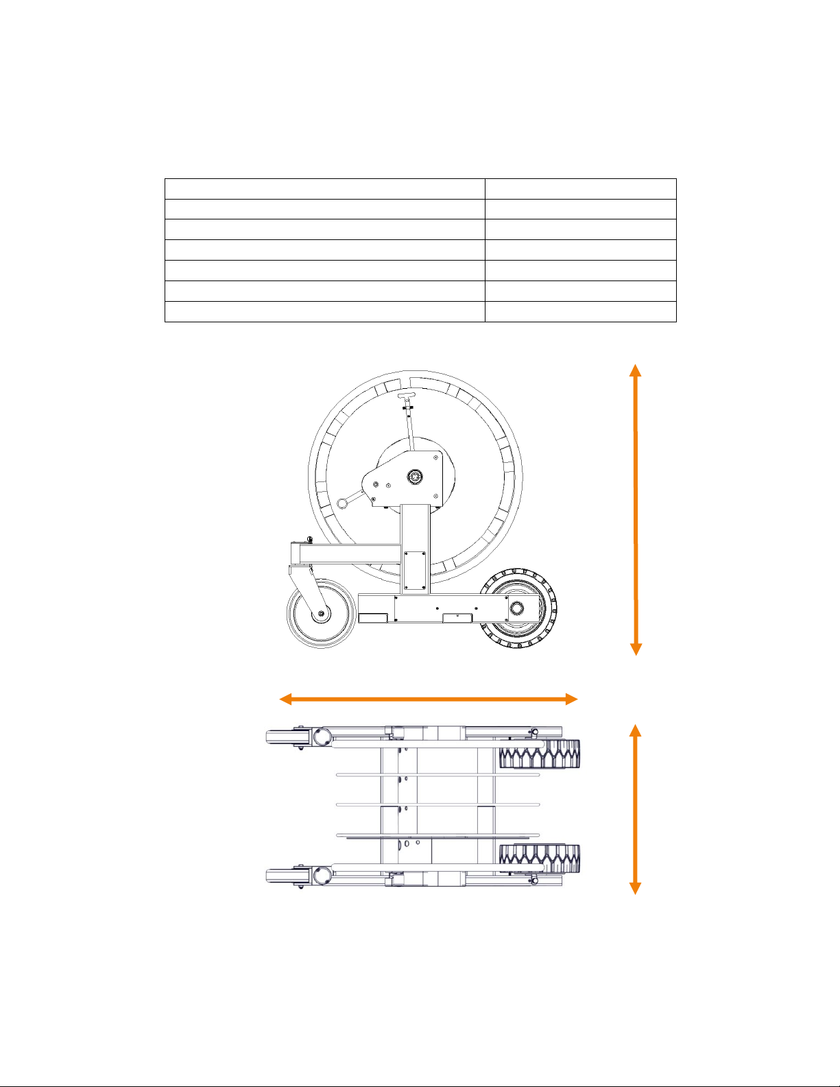
Specifications
Maximum Height
65 inches
Max Wheel Base Length
60 inches
Wheel Base Width
32 inches
Unloaded Vehicle Weight
700 lbs.
Total Vehicle Capacity
2700 lbs.
Conductor Reel Capacity
1500 lbs.
Ground Reel Capacity
500 lbs.
65 in.
Figure 2a: ReelRover Specifications Side View
32 in.
60 in.
Figure 2b: ReelRover Specifications Aerial View

7
Safety Procedures
Read and understand prior to using this product.
This machine is designed for certain applications only. Cerrowire cannot be responsible for issues
arising from modification. We strongly recommend this machine is not modified and/or used for
any application other than that for which it was designed. If you have any questions relative to a
particular application, DO NOT use the machine until you have first contacted Cerrowire to
determine if it can or should be performed on the product.
§ Never overload the ReelRover. Stay within rated capacity.
§ Do not operate this ReelRover if damaged or not in proper working order.
§ Never put your feet, hands or any other body part under the frame assembly.
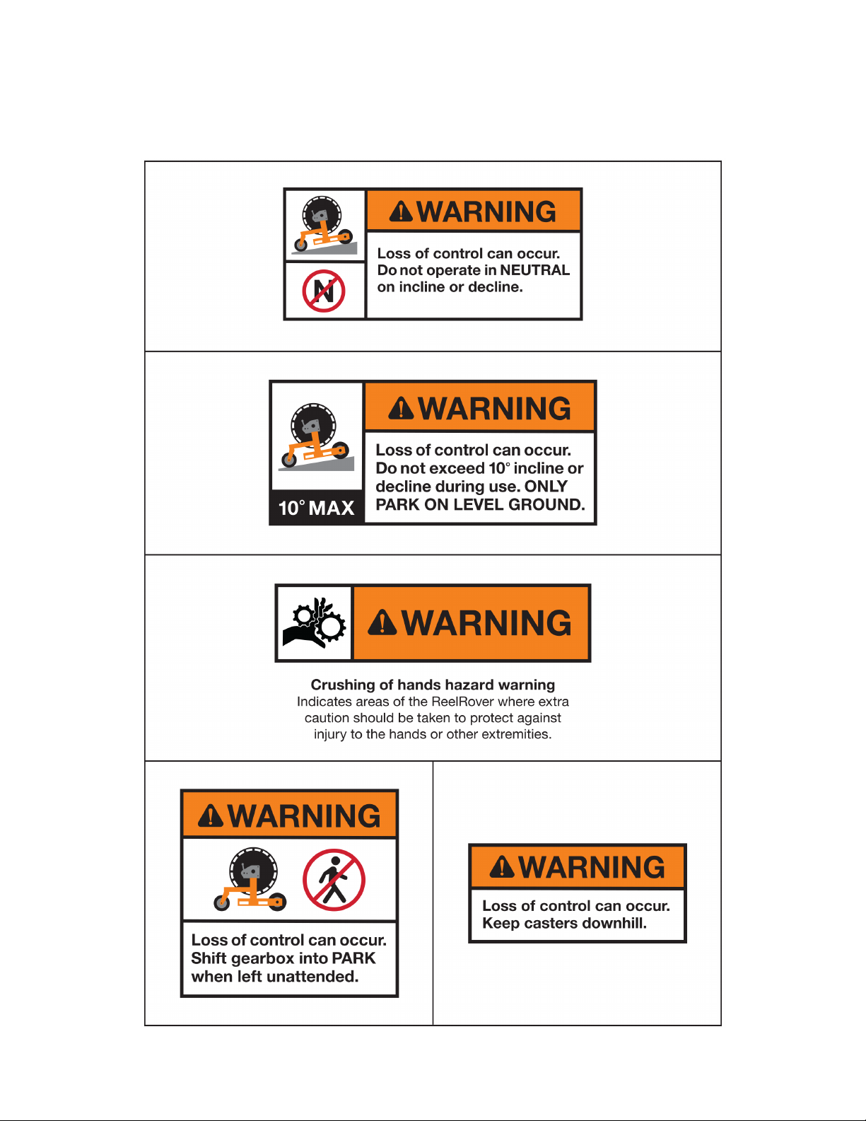
§ Do not leave ReelRover unattended or in NEUTRAL on a hill or incline.
§ Do not operate ReelRover on a hill or incline with an angle greater than 10°.
§ Do not allow the ReelRover to drop from one level to another.
§ Always ensure gearbox is in PARK on both sides of the ReelRover when securing
ReelRover for loading/unloading wire from reel.
§ When not in use, place both gearboxes in PARK.
§ Do not drag, push, or tow ReelRover with another vehicle or device.
§ Always keep hands on ReelRover while it is in motion.
§ Do not stand or sit on any part of the ReelRover.
§ Do not attempt to disassemble or repair the ReelRover unless doing so with
authorization from Cerrowire or by ReelRover maintenance technicians/organizations.
§ Do not attempt to lift the ReelRover using a strap or chain. The ReelRover should only
be lifted using a properly rated forklift or pallet jack in the locations shown in this manual.
§ Always use proper safety equipment when using ReelRover, including protective
eyewear and appropriate safety footwear.
For technical questions, please contact Cerrowire
8
Symbols and Warnings

9
10
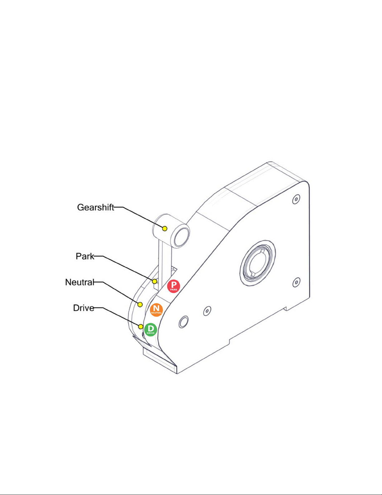
Gearbox
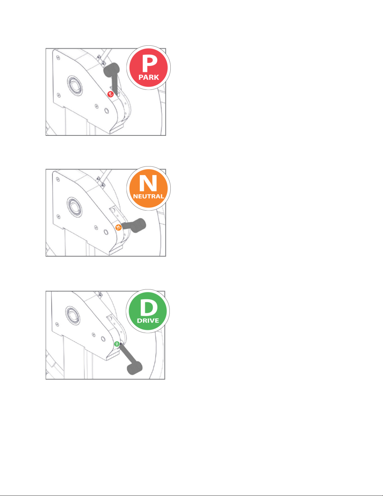
The gearbox has three settings: PARK, NEUTRAL, and DRIVE. These settings control the
rotation of the drive wheels and reel, as well as their relation to each other. The left and right
gearboxes are independently set using the gearshift as shown in Figure 3.
To change the setting, move the gearshift to the desired position (P, N, or D as labeled), making
sure the spring detent positively locates in the corresponding hole. The positions of the gearshift
for each setting can be seen in Figures 4 through 6.
Figure 3: Gearbox Settings
11
Figure 4: PARK Gearshift Position
PARK (P)
- Drive Wheels LOCKED and cannot be
rotated
- Reel is FREE to rotate in either direction
- Uses:
o Loading or Unloading wire from
reel
o Securing ReelRover for
transportation or shipping, via
fork truck or trailer
o Leaving the ReelRover unattended
NEUTRAL (N)
- Drive Wheels FREE to rotate in either
direction
- Reel is FREE to rotate in either direction
- Uses:
o Pushing ReelRover across flat
ground
o Manually steering and positioning
ReelRover at job site or
distribution center
DRIVE (D)
- Drive Wheel rotation is controlled by the
speed and direction of reel rotation. Three
(3) rotations of the reel is equal to
approximately one (1) rotation of the
drive wheels (3:1 gear ratio)
- Reel rotation drives the motion of the
ReelRover in the same direction of reel
rotation, either forwards or backwards
- Uses:
o Controlling ReelRover down an
incline
o Mechanical advantage up an
incline
o Going over obstacles, such as job-
site debris not to exceed 2 inches
in height.
Figure 5: NEUTRAL Gearshift Position
Figure 6: DRIVE Gearshift Position
12
Basic Operation
Operating the ReelRover in PARK
When both gearboxes are placed in PARK, as shown in Figure 4, neither drive wheel will be able
to rotate, effectively locking the ReelRover in position. The reel is still able to turn freely, allowing
wire to be loaded or unloaded without the ReelRover moving.
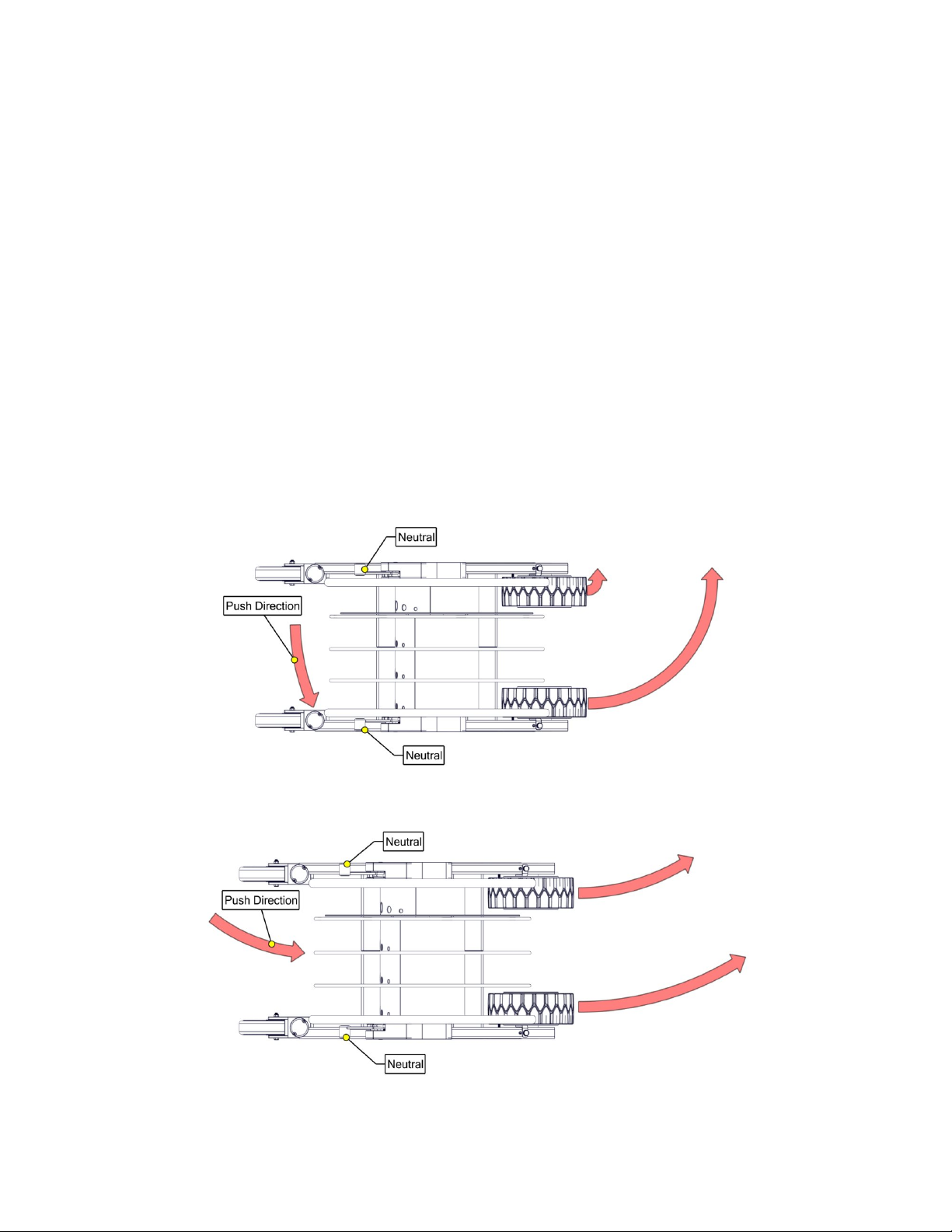
Operating the ReelRover in NEUTRAL
When both gearboxes are placed in NEUTRAL, as shown in Figure 5, the reel and drive wheel
rotation are both free and independent. The ReelRover can be pushed manually with no
mechanical advantage in this setting.
Steering in NEUTRAL
The ReelRover can be steered in NEUTRAL by pushing in the direction of the desired turn. The
larger the angle, the sharper the turn.
Figure 7a: Sharp Turn in NEUTRAL
Figure 7b: Gradual Turn in NEUTRAL
13
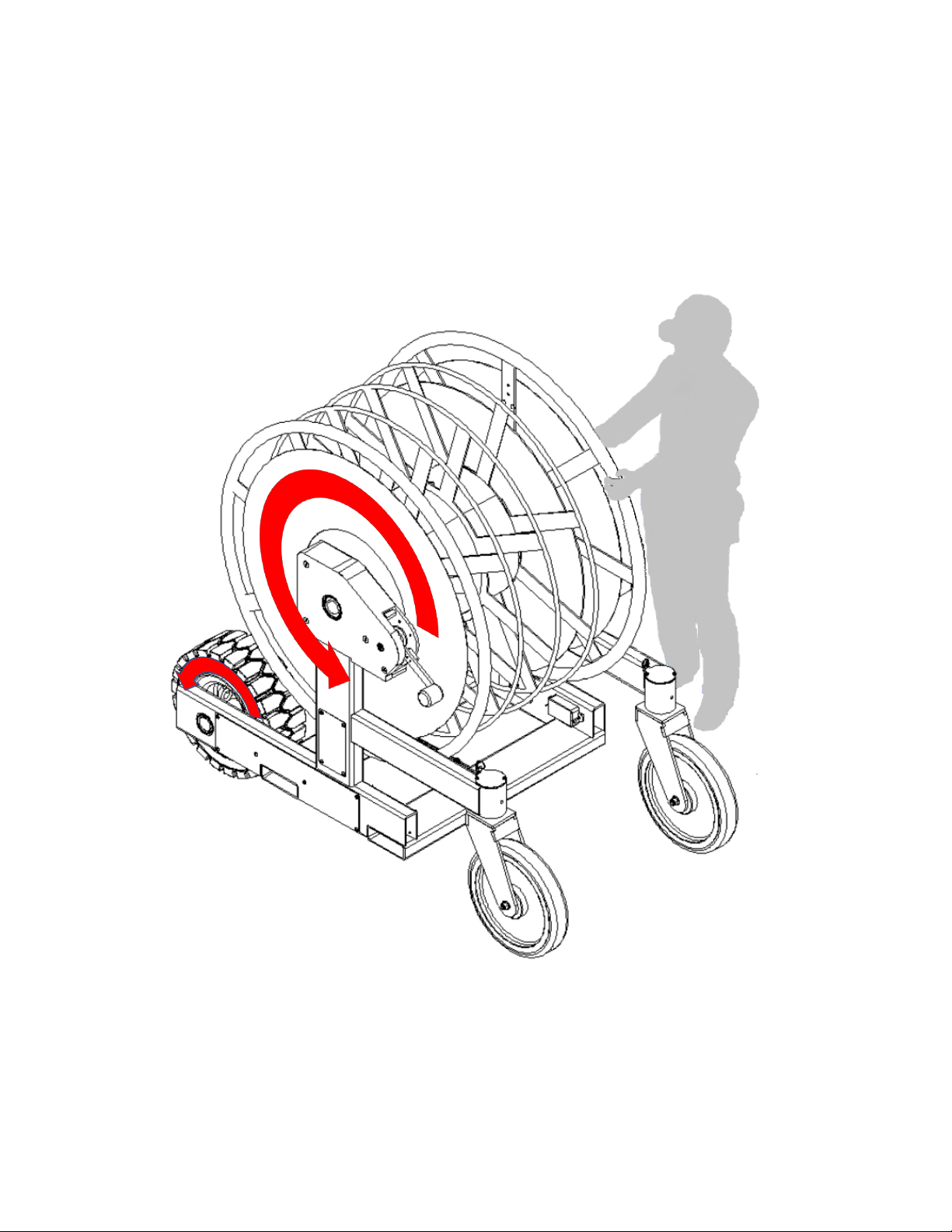
Operating the ReelRover in DRIVE
When both gearboxes are placed in DRIVE, as shown in Figure 6, the reel rotation is locked to
the drive wheels with a gear reduction. The ReelRover can be driven either straight forward or
back using the reel rotation. The gear reduction allows for driving the ReelRover uphill, controlling
the speed downhill, and going over obstacles.
Figure 8: Reel and Drive Wheel Rotation
14
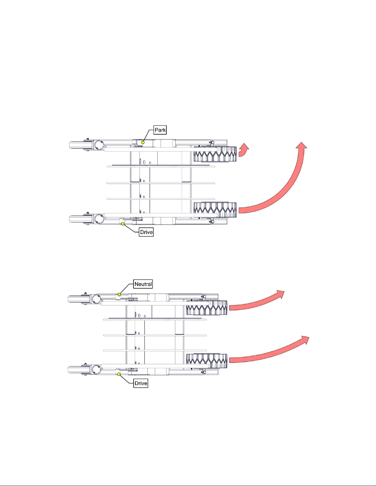
Steering in Drive
When only one gearbox is placed in DRIVE, the ReelRover can be turned in the direction of the
parked wheel. If the other gearbox is placed in PARK, the turn will be sharp (almost 90 degrees).
If the other gearbox is placed in NEUTRAL, the turn will be more gradual, depending on factors
such as ground type and weight of wire on reel.
Figure 9a: Sharp Turn in DRIVE
Figure 9b: Gradual Turn in DRIVE
15
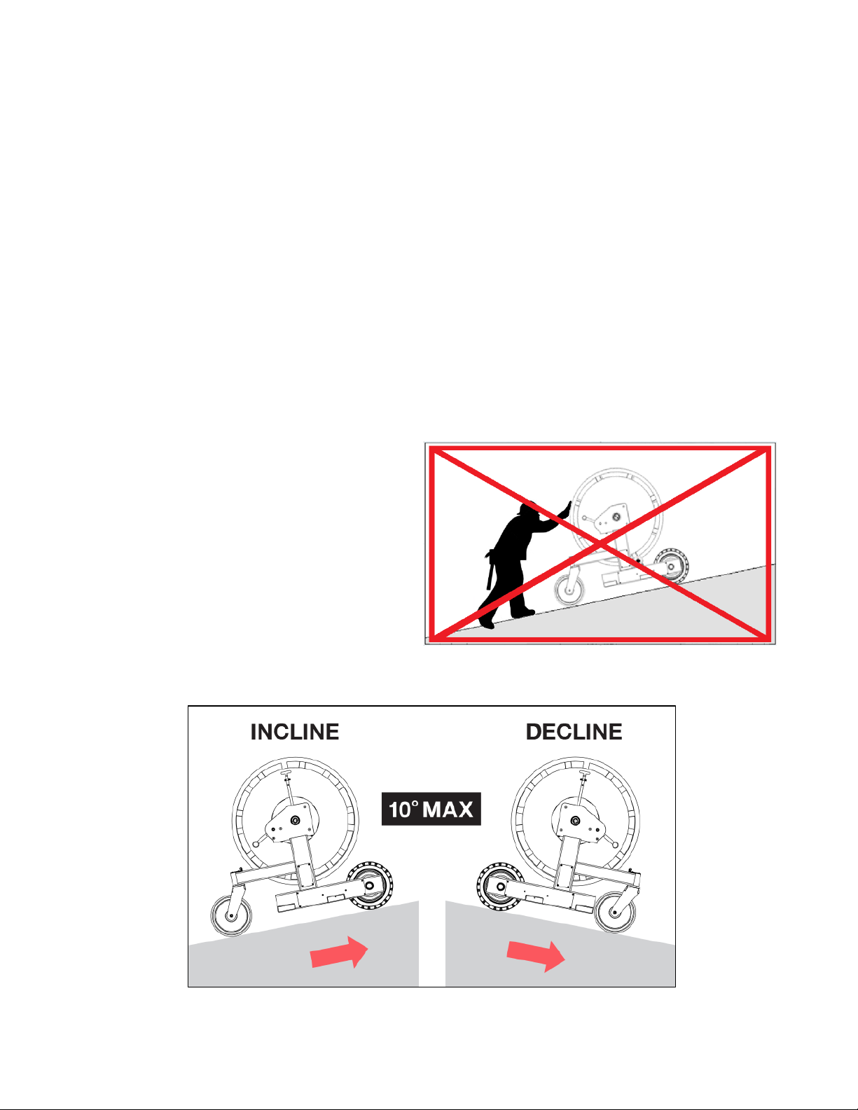
Operating the ReelRover in Drive on a Ramp or Grade
It is imperative that the following safety precautions be taken when driving ReelRover or
controlling its speed on ramps and grades:
Potential Hazards:
§ There is a danger of tip over when traveling on ramps and grades.
§ Falling off the edge of the ramp or grade.
§ Skidding or slipping due to wet or icy conditions.
§ Free descent on a grade.
Requirements and Recommended Practices:
§ The ReelRover should NEVER be operated on a ramp or grade with an angle greater
than 10° as indicated by the ReelRover shown in Figure 10b.
§ Always look in the direction of travel.
§ The caster wheels should always be downgrade regardless of direction of travel
when operating on an incline, shown in Figure 10b.
§ Never turn on a ramp or grade. Set the gearboxes and position the ReelRover on a flat
surface prior to using the grade so that ReelRover may move straight up or down the
ramp or incline.
§ Never stand or walk directly
downgrade of ReelRover, Figure 10a.
§ Maintain a safe distance from the
edge of the ramp or grade.
§ Keep working surfaces clear and
clean.
§ NEVER ALLOW FREE DESCENT
ON A GRADE. ALWAYS PLACE
THE REELROVER IN DRIVE ON
FLAT GROUND AND CONTROL
THE UNIT DURING DESCENT.
Figure 10a: Never Stand or Walk
Downgrade of ReelRover
Figure 10b: Caster Wheels Should Always Be Downgrade

16
Ground Reel
The ReelRover can be equipped with a free-spinning Ground Reel that can be locked or unlocked
with the reel lock handle as shown in Figure 11a. This allows for simultaneous loading and
unloading of smaller gauge ground wire with the conductor wire, without the need for reel
disassembly.
Figure 11a: Reel Lock
Figure 11b: Reel Lock Indication
Figure 11c: Reel Unlock Indication

17
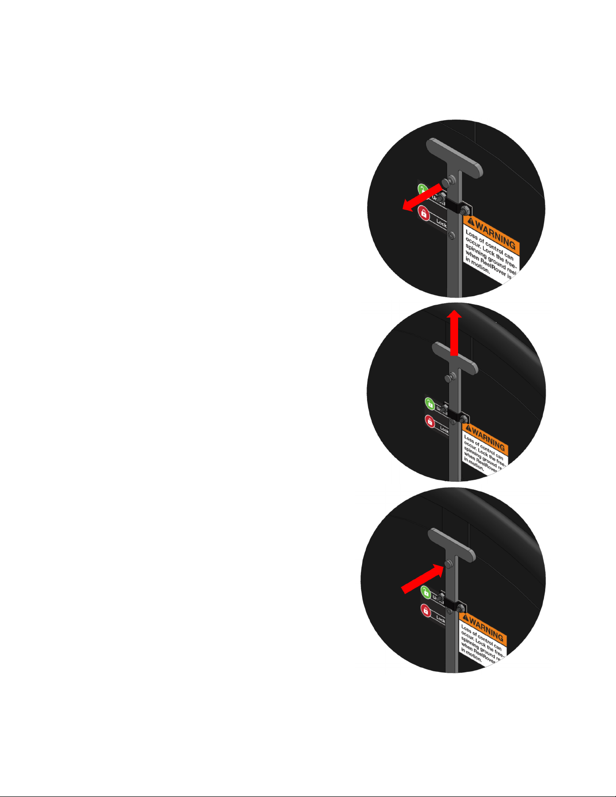
Ground Reel: Lock Procedure
IMPORTANT: Make sure the ReelRover gear selectors (both sides) are placed in the
PARK position.
Step 1:
Pull plunger knob out so that the Free-Spinning Ground
Lock Handle may slide.
Step 2:
Slide the Free-Spinning Ground Lock Handle toward
center of reel until the Position Indicator aligns with the
Lock indicator.
Step 3:
Confirm that the plunger knob has returned to the closed
position (no longer pulled out) and that the Position
Indicator is still aligned with the Lock indicator.
The Ground Reel is now rotationally locked to the
Conductor Reel.
Uses:
o Loading ground wire with conductor wire.
o DRIVE & NEUTRAL settings.
Figure 12: Reel Lock Procedure
18
Ground Reel: Unlock Procedure
IMPORTANT: Make sure the ReelRover gear selectors (both sides) are placed in the
PARK position.
Step 1:
Pull plunger knob out so that Free-Spinning Ground
Lock Handle may slide.
Step 2:
Slide the Free-Spinning Ground Lock Handle toward
perimeter of reel until the Position Indicator aligns with
the Unlock indicator.
Step 3:
Confirm that the plunger knob has returned to the
closed position (no longer pulled out) and that the
Position Indicator is still aligned with the Unlock
indicator.
Once unlocked, the Ground Reel is free to spin
independently of the Conductor Reel.
Uses:
o Even payout of ground wire with conductor
wires.
Figure 13: Reel Unlock Procedure

19
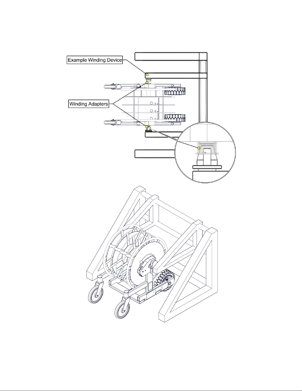
Winding Adaptor
Inserting Winding Adaptor
The winding adaptor can be inserted
into either gearbox as shown in Figure
14. The winding adaptor is used as an
attachment point for the reel coiling
device.
Align the reel coiling device centerline
with the centerline of the adaptor, Figure
15.
Positioning ReelRover
Position ReelRover, using either the
DRIVE or NEUTRAL settings (see Fig.
17a & b), and operate the winding
device as outlined in the manual for the
specific device.
The device’s centerline cone or shaft
should line up with the outer bore of the
winding adaptor, Figure 15 & 16a, and
the engagement pins adjusted to fit into
the outer holes of the adaptor.
Figure 14: Winding Adaptor Insertion
Figure 15: Winding Device Centerline Location
20
Figure 16b: Winding Device Use with ReelRover Winding Adaptor
Figure 16a: Winding Device Use
with ReelRover Winding Adaptor
Aerial View and Detail
Other manuals for ReelRover
3
Table of contents
Other Cerrowire Tools manuals

Popular Tools manuals by other brands


Delta
Delta VERSA-FEEDER 36-865 instruction manual

OEM Tools
OEM Tools 24449 Operating instructions and parts manual

Aircat
Aircat 6410 Operations manual & parts list

Aero-motive
Aero-motive RB2 Series Service manual

Power Fist
Power Fist 1/2 in. Air Ratchet and Socket Set user manual

EGAmaster
EGAmaster CURVAMATIC-2 operating instructions