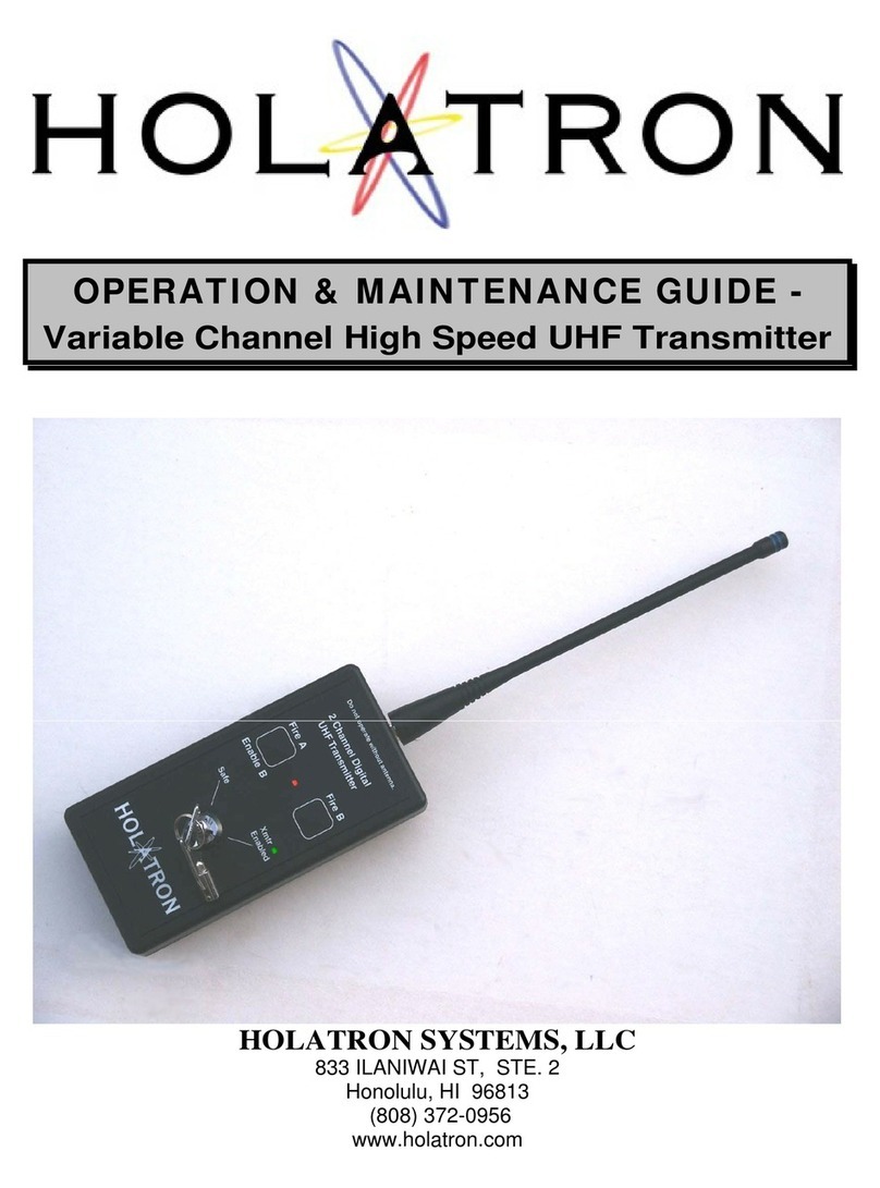
Holatron RFLS-MK3HSXT Operating manual

OPERATION & MAINTENANCE GUIDE -
Acoustic Triggered
High Speed
UHF Transmitter
HOLATRON SYSTEMS, LLC
833 ILANIWAI ST, STE. 2
Honolulu, HI 9681
3
(808) 372
-
0956
www.holatron.com

2
of 1
4
WARNING
Holatron Systems specializes in the design and manufacture o
f standard and custom electronic
control systems where reliability and error free data communication are critical. The transmitter
described in this manual is part of a system intended to remotely actuate pyrotechnic or other
hazardous devices, and the com
ponents of this system have been carefully designed to
minimize the possibility of accidental actuation of such devices. Holatron’s design goal is to
ensure that data communication errors due to radio interference or to insufficient signal strength
due to
low battery, exceeding specified range, or conductive objects in the signal path will result
in failure of intentional actuation rather than unintended actuation. Techniques used to achieve
this design goal are described in section 1.
9
. Though the probabil
ity of unintended actuation is
extremely small, it cannot be guaranteed to be zero. Therefore,
it is important that the user
not enable the receiver until all persons who might be harmed by accidental actuation
are in a safe area
.
As a condition of purcha
se, the user must acknowledge awareness and agreement that
utilization of this product and participation in activities utilizing fireworks, rockets, and explosives
is an ultra
-
hazardous activity carrying implied and explicit risks of injuries and damages t
o the
user and to other participants. The user assumes the risk connected with the utilization of this
product and all risks of participation in the activities for which this product is sold. User
acknowledges that he/she/it has the necessary and required
skill, expertise, training and
licensing, as may be applicable or necessary by custom, usage, trade or law, to engage and
participate in the ultra
-
hazardous activities connected with the use, purchase, transportation, or
employment of the products sold un
der this agreement. User acknowledges that Holatron
Systems, LLC, has not and will not conduct any investigation into the skill, expertise, training
and licensing, as may be applicable or necessary by custom, usage, trade or law, of the user or
of user’s a
gents, employees and assigns, to engage and participate in the ultra
-
hazardous
activities connected with the use, purchase, transportation, or employment of this product. User
specifically agrees that Holatron Systems, LLC, its officers, employees, and age
nts shall not be
liable for any claim, demand, cause of action of any kind whatsoever for, or on account of death,
personal injury, property damage or loss of any kind resulting from or related to user’s or user’s
employees’, agents’ or assigns’ use of thi
s product, and user agrees to indemnify, defend in any
action at law, and hold harmless Holatron Systems, LLC, from same, whether brought by the
user, user’s agent, or assigns, or any third party.
Usage of this transmitter is authorized under FCC Rules an
d Regulations as listed in CFR
47
Ch.1 (10
-1-
96 Edition), p
art 15, subpart C, sections 15.209 and 15.231. This equipment has
been tested and assigned
FCC ID number: OI4RFLS1XT.
Any changes or modifications to the hardware not expressly approved by
the party
responsible for compliance could void the user’s authority to operate the equipment.

3
of 1
4
This manual is divided into two sections. The first is a description of the system hardware. The
second covers the recommended operating and maintenance pro
cedure.
1.0
HARDWARE DESCRIPTION.
The model RFLS
-
MK3
HS
XT
Fixed
Channel
High Speed
UHF Transmitter
with
sequential acoustic trigger
is a low power
six
channel, safety locking, hand
-
held remote
control transmitter
which can transmit commands over any of six
different digital
channels.
The transmitter’s channel setting is fixed in software and cannot be changed.
A label displaying the channel setting is affixed to the top of the transmitter next to the
antenna.
Transmitters
fixed
to separate digital channel nu
mbers can transmit
simultaneously without interfering with each other.
This permits up to six different
receivers or groups of receivers to be controlled by separate transmitters
simultaneously.
The transmitter will only actuate receivers whose digital cha
nnel
switches are set to select the same channel as the transmitter.
Thus, multiple
transmitters may be used to actuate different selected receivers even though all operate
on the same frequency. Transmitters fixed to the same digital channel number will
i
nterfere with each other and result in failure
-
to
-
fire when actuated simultaneously.
When
used with
RFLS
-
96
HS
RC
,
RFLS
-
496
HS
RC
, or RFLS
-9
12HS
RC
receivers, a
range of ½ mile can be achieved.
All inscriptions on the transmitter panel are
luminescent to faci
litate use of the transmitter in a dark environment. The panel will
continue to glow for two to three hours after being exposed to a bright light source. The
transmitter’s two
commands
are digitally encoded and amplitude modulated on a single
carrier frequ
ency of 418 MHz
(or optionally 433.96
MHz)
. This frequency is controlled by
a SAW (surface acoustic wave) device for exceptional stability. No alignment or tuning
procedures are ever required to
maintain optimum performance.
The command signal is
transmit
ted by amplitude modulating the carrier to indicate to the receiver which of the
transmit buttons is depressed or whether an acoustic event has been detected.
In
acoustic trigger mode (
digital switch positions 0
–
B
), the “A command” signal (semi
-
automati
c fire) is transmitted for 250 msec when an acoustic impulse exceeding the
selected threshold is detected by the rear panel microphone while the “
Fire A / Enable B
”
button is depressed, and it is transmitted continuously while the “B” button and “A”
button are depr
essed simultaneously, permitting the “B” button to serve as an acoustic
event simulator.
In
normal command
mode
(
digital switch positions C
–
F
), t
he modulated RF output
occurs continuously while
either
of the two transmit buttons is depressed
.
Resulting
receiver output is continuous while the “A command” signal
(semi
-
automatic fire)
is being
transmitted, and the receiver fires outputs in rapid
-
fire mode at a rate selected by the
transmitter’s FIRE RATE SELECTION SWITCH while the “B command” signal is bein
g
transmitted.

4
of 1
4
The user has access to the following components:
1.1
THE ANTENNA.
The RF signal is radiated by a quarter
-
wave flexible whip antenna which screws
onto the top end of the transmitter box.
The transmitter should never be
operated without this a
ntenna in place, as damage to the RF components
could result.
Such operation will void the warranty.
Antennas with red rings are used for 433 MHz, and antennas with blue rings are
used for 418 MHz.
Be careful not to overtighten the antenna when screwing it on,
as this could cause its mating connector to rotate and break its internal
connection. Rotation could also occur, with the same result, when subsequent
removal of an overtightened antenna is attempted. The recommended way to
install the antenna is to
grasp it by its small diameter upper part and rotate gently
in a clockwise direction until increased resistance is felt. It need not be tight to
achieve a good electrical connection. When removing the antenna for storage,
observe the base of the mating con
nector to ensure that it is not rotating. If the
antenna is so tight that rotation is occurring, grasp the hex base of the mating
connector with long nose pliers, and then unscrew the antenna.
1.2
THE SAFETY LOCKING SWITCH.
The Safety Locking Switch is a min
iature keylock with two positions, “Safe” and
“Xmtr Enabled”. In the “Safe” position no RF output occurs even if a button is
pressed. In the “Xmtr Enabled” position modulated RF output occurs
continuously while a button is pressed. Whether transmitting or
not, a
green
warning indicator near the switch flashes whenever the switch is in its “Enabled”
position and the battery voltage is above the low battery detect threshold.
Approximately 1 milliamp is drained continuously from the battery while the
transmitt
er is enabled and not transmitting. So this switch should always be
turned to the “Safe” position while the transmitter is not being used. Keys are
interchangeable, as all Holatron RFLS
-
6HS
XT transmitters are keyed the same.
Firing on all receivers set to
the transmitter’s digital channel always commences
at cue 1 after the transmitter has first been enabled. Thus all receivers on this
transmitter’s fixed channel can be reset to cue 1 at any time by turning this switch
momentarily to “Safe” and then back t
o “Transmitter Enabled”.

5
of 1
4
1.3
THE “XMTR ENABLED” INDICATOR.
This green lamp, located at the “Enabled” position of the lockswitch, warns the
user that transmission will occur when a button is pressed or an acoustic event is
sensed, and that battery drain is occurring. It also verifies that battery voltage is
adequate to transmit a signal over the specified range.
When the transmitter is turned on (transmitter enabled) with the keylock switch,
battery status is indicated by the flashing of this lamp. It is of
sufficiently high
intensity to be visible in direct sunlight and will flash intermittently in bursts of
one, two, or three flashes at a time if the battery has enough capacity to power
the transmitter. If no flashing occurs, the battery must be replaced b
efore the
transmitter can be used reliably. Three flashes per burst indicate that the battery
has full capacity, two flashes indicate that its capacity is beginning to diminish,
and one flash indicates that it is near the end of its useful lifetime in whic
h case it
should be replaced immediately after the current use. Adequate transmitter
output to achieve the specified range will occur as long as the battery voltage is
above approximately 7.0 volts, but the battery voltage will drop rapidly at this
point.
If in acoustic trigger mode (digital switch positions 0
–
B), this indicator will glow
continuously while the “
Fire A / Enable B
” button is pressed. Only while glowing
continuously can command transmission occur in response to an acoustic event
or a “Fire B” butto
n press.
1.4
THE FIRE BUTTONS.
These buttons are snap action dome switches under a sealed overlay, labeled
“Fire A” and “Fire B”, respectively. They have a high spring constant which
requires a firm depression for actuation, decreasing the likelihood of acci
dental
depression. The enabled transmitter can be kept in a shirt or jacket pocket
without fear of accidental button depression.
The action of the buttons depends
on the position of the transmitter’s digital switch.
1.4.1
Acoustic
Trigger Mode (digital switch p
ositions 0
–
B)
For safety, transmission
is enabled only
while the “
Fire A / Enable B
”
button is depressed
.
Be aware that fire command transmission can
occur immediately upon depression of the “
Fire A / Enable B
” button
if acoustic events are occurring. Do not
press the “
Fire A / Enable B
”
button until
it is quiet, and
all persons who might be harmed by
device actuation are in a safe area.
W
hile “
Fire A / Enable B
” is
depressed, the green “Xmtr Enabled” indicator will glow continuously, and
“A command” (semi
-
automatic fire) trans
mission will occur while an
acoustic event is being detected by the rear
-
panel microphone. Each
detected acoustic event will result in the firing of the next sequential
receiver output. Transmission will occur for 250 msec following an
acoustic event, and
maximum sense rate is approximately 3 events per
second. An acoustic event is defined as a sound impulse exceeding the
switch selected threshold. (See section 1.7)

6
of 1
4
If the “Fire B” button is pressed while “
Fire A / Enable B
” is also pressed,
the
“A command” is transmi
tted, resulting in the firing of the next
sequential receiver output. The output remains on until at least one of the
buttons is released.
1.4.2
Normal Command Mode
(digital switch positions
C – F)
In this mode the transmitter is idle while no buttons are pres
sed.
Continuous transmission occurs while “
Fire A” or “Fire B” is pressed.
Output firing pulses are stretched to a minimum duration of 0.6 seconds
in the receivers to ensure that cues fire reliably, even when the fire
buttons are pressed for a shorter peri
od of time. Note that it is not
necessary to wait for the completion of the 0.6 second firing pulse period
before firing subsequent cues. They can be fired as fast as the operator
can press the button, provided that each button depression lasts at least
0.
1 second, followed by at least 0.1 second with the button released. If
many transmitters are transmitting simultaneously, it may be necessary to
depress a fire button slightly longer than 0.2 second in order to ensure an
output from the receiver
.
1.5
THE TRANSMIT INDICATOR.
This is a high intensity
red
indicator, visible in direct sunlight, that lights
continuously while the transmitter is generating RF output. It is located between
the two buttons. It will light even if the battery voltage is below the low b
attery
detect threshold.
It can be used to check microphone sensitivity by indicating
acoustic event detection in acoustic mode with the receiver(s) switched off. “
Fire
A / Enable B
” must be depressed
while
conduct
ing
this check
.
Adequate
m
icrophone
sensitivity can be verified
by observing a red flash each time an
even
t is detected. This is a useful tool for setting microphone sensitivity with the
digital switch. (See section 1.7)
1.6
THE BATTERY.
Power is supplied from an alkaline 9 volt battery, accessible beneath a slide
-
out
door on the back side of the transmitter. T
his battery should be replaced when
required by conditions described in section 1.3 above. In order to prevent the
possibility of damage due to battery leakage, the battery should always be
removed if the transmitter is to be stored for a prolonged period.
Damage due to
battery leakage is not covered under the warranty.

7
of 1
4
1.7
THE DIGITAL
SWITCH.
A 16 position miniature rotary switch is accessible through a hole in the back of
the transmitter. The switch is located on the left edge of the internal printed circ
uit
board, as shown in the following photo. It can be set to digital channels
0
–
9 or
A
–
F by rotation with a small screwdriver. The setting, or position, of this switch
sets the transmitter operating mode and the acoustic event detection threshold
as
shown in the following table. Positions 0
–
B select acoustic trigger mode, with
higher switch settings corresponding to higher thresholds and lower acoustic
sensitivity. Positions C
–
F select normal command mode (buttons only) with the
switch setting se
lecting the automatic fire rate for
depressions of the “Fire B”
button
.
Holatron Systems can supply custom fire rates if required.
NOTE:
Automatic firing always commences at the next cue after the last one
fired, whether it was semi
-
automatic or automatic
. Semi
-
automatic firing
always commences at the next cue after the last semi
-
automatic cue
fired, even if automatic cues have been fired in the meantime.
Semi
-
automatic or automatic firing
always commences at cue 1 after the
transmitter has first been ena
bled. Thus all receivers on the transmitter’s
fixed channel can be reset to cue 1 at any time by turning the
transmitter’s safety locking switch momentarily to “Safe” and then back to
“Transmitter Enabled”.
(Transmitter with rear c
over removed)
Digital Switch
Microphone

8
of 1
4
The access hole for the digital switch enables the operator to view the switch
setting and insert a small screwdriver to change it without having to remove the
rear cover.
(
Tr
ansmitter back shown without and with adhesive disc in place.
)
An adhesive disc normally covers the access hole for the digital switch to keep
out contaminants and conductive objects. The disc can be peeled back when it is
necessary to view or change
the switch setting.
Digital Switch
Access Hole
Access Hole Covered
with Adhesive Disc
Microphone
Hole
Battery Access Door

9
of 1
4
Xmtr Digital
Switch Setting
“Fire A / Enable B” Action
“Fire B” Action
0
Enables transmission of a semi
-
automatic fire command upon
detection of acoustic event or upon
“Fire B” button depression. Minimum
acoustic threshold (max
imum
acoustic sensitivity).
If “Fire A” button is
also
pressed,
xmts
a
semi
-
automatic (single
-
shot)
fire command
continuously until
one or both
button
s are
released.
1
Same as above with higher acoustic
threshold.
Same as
above
.
2
Same as above with hi
gher acoustic
threshold.
Same as above.
3
Same as above with higher acoustic
threshold.
Same as above.
4
Same as above with higher acoustic
threshold.
Same as above.
5
Same as above with higher acoustic
threshold.
Same as above.
6
Same as above wit
h higher acoustic
threshold.
Same as above.
7
Same as above with higher acoustic
threshold.
Same as above.
8
Same as above with higher acoustic
threshold.
Same as above.
9
Same as above with higher acoustic
threshold.
Same as above.
A
Same as above
with higher acoustic
threshold.
Same as above.
B
Same as above with highest acoustic
threshold (minimum acoustic
sensitivity).
Same as above.
C
Semi
-
automatic firing.
(Single shot, sequential)
Automatic firing (rapid fire) at a rate
of 7.69
shots / s
econd while the
button is pressed. (0.13 second per
shot)
D
Semi
-
automatic firing.
(Single shot, sequential)
Automatic firing as above at a rate
of 10
shots / second. (0.1 second
per shot)
E
Semi
-
automatic firing.
(Single shot, sequential)
Automatic fi
ring as above at a rate
of 14.3
shots / second. (0.07
second per shot)
F
Semi
-
automatic firing.
(Single shot, sequential)
Automatic firing as above at a rate
of 20
shots / second. (0.05 second
per shot)

10 of 1
4
1.8
REMOTE FIRE JACK.
Transmitters that include
this
optional
feature can be actuated remotely through a
two conductor shielded cable plugged into a jack located on the left side of the
transmitter box. The jack accepts a standard 1/8” miniature stereo phone plug
.
The cable’s shield connects to the plu
g’s “shell”, the red lead to the plug’s “tip”,
and the black lead to the plug’s “ring”.
The transmitter is actuated remotely by connecting the tip to the shell (red to
shield) to duplicate the action of the
“
FIRE A
”
button, and
by
connecting the ring
to t
he shell (black to shield) to duplicate the action of the
“
FIRE B
”
button.
The
transmitter’s FIRE buttons
also remain
operational while the cable is plugged in.
NOTE:
T
he transmitter should always be turned off when plugging in
or
extracting
the remote cable to ensure that no fire commands are
accidentally transmitted if jack contacts should be momentarily shorted
during the insertion
or extraction
.
1.9
RADIO INTERFERENCE REDUCTION.
For obvious safety reasons,
Holatron's design goal is to ensure that data
c
ommunication errors due to radio
interference or to insufficient signal strength
due to low battery,
e
xceeding
specified range, or conductive objects in the signal
path will result in
failure of intentional actuation rather than unintended actuation.
This
goal is
achieved by transmitting a
64
bit noise
-
tolerant
code repeatedly while
a transmitter
button is depressed.
6
0 of these bits must match the pattern
expected by the
receiver
.
Thus, there is one chance in
(2 to the
60
th
power)
of an
actuation occurring
due to reception
of a random signal.
Expressed in decimal
numbers, this is (
1.1529
times 10 to the
18
st
power,
or
11529
followed by
14
zeroes).
This is a probability of
8.6736
times 10 to the
-
19
th
power
(
or a
decimal
point followed by
18
zeroes followed
by
86736
). Though th
is
probability of
unintended actuation is extremely small, it cannot be guaranteed
to be zero.
Therefore
,
it is important that the user not arm the receiver until all persons
who might be harmed by accidental actuation are in a safe are
a.
Additional protection is offered by use of 418 MHz as the operating frequency.
This frequency is sparsely used only by low power transmitters with a maximum
range of approximately 100 yards. It is not commonly used by auto security
systems, garage door
openers, radio control models, cordless
or cellular
telephones,
wireless microphones, or two way communications equipment.
Because this system
operates in the UHF region, interference from lamp
dimmers, electrical discharges,
and other natural sources is
also minimal.
No
instances of false triggering
with this communications technology
have been
reported to date.

11 of 1
4
1.10
SPECIFICATIONS.
Parameter
Minimum
Typical
Maximum
Carrier Frequency, MHz.
417.96
418.02
418.08
Carrier Frequency, MHz. (optional)
432.9
0
43
3.
96
43
4
.0
2
Range (line
-
of
-
sight with
RFLS
-96RC
-
49
6
RC r
eceiver
s)
½ mile
Delay from
start of button depression
to receiver output
(fewer than 4
transmitters transmitting
simultaneously)
50 msec
75
msec
Delay from
start of button depression
to receive
r output
(more than 3
transmitters transmitting
simultaneously)
100 msec
400
msec
Button depression time per cue (fewer
than 4 transmitters transmitting
simultaneously)
100 msec
Button depression time per cue (more
than 3 transmitters transmitting
sim
ultaneously)
400 msec
Delay from
acoustic event detection
to
receiver output
(fewer than 4
transmitters transmitting
simultaneously)
100 msec
Delay from
acoustic event detection
to
receiver output
(more than 3
transmitters transmitting
simultaneously
)
425
msec
Acoustic event transmission duration
250 msec
Processing rate, acoustic events / sec
3
Battery current, average, (enabled)
Battery current, average, (xmting)
1.0 mA
4.0 mA
Battery life (enabled, not transmitting)
500 hrs
Low Ba
ttery Detect Threshold
7.7 V
Transmitter Supply Voltage
7.0 V
2.0
OPERATION AND MAINTENANCE.
This
section describes the recommended operating procedure and maintenance for the
transmitter
-
receiver system.
2.1
OPERATION.
2.1.1
With the receiver turn
ed off and its
a
rm
switch set
to
“
disarm
” (
RFLS
-
496
HS
RC)
or “safe” (RFLS
-
96
HS
RC
& RFLS
-
912HSRC
)
, connect
devices to the receiver outputs.

12 of 1
4
2.1.2
With the
a
rm
switch still in the previous position, turn on the receiver.
Verify a flashing green battery indica
tor
on the
receiver
module
. This
indicator will flash intermittently in bursts of one, two, or three flashes at a
time if the battery has enough capacity to power the receiver. If no
flashing occurs, the receiver cannot be used reliably. Three flashes per
burst indicate that the battery is fully charged, two flashes indicate that its
charge is beginning to diminish, and one flash indicates that it is near the
end of its useful charge, in which case it should be
replaced
immediately
after the current use.
2.1.3
E
nable the transmitter, and
with the receiver’s ARM switch in “safe” or
“disarmed” position
,
perform a range test by observing the
green
activity light on the
receiver
while pressing
a
transmitter button
.
There
should be
no intervening conductive objects
f
or most reliable operation.
All receivers must be
elevated
12” or more
above ground level
to achieve
specified range. When
transmitting over water
, range will normally
exceed the specified value.
Range of the receiver is typically ½ mile, and its range c
an be tested with
the arm switch off by observing the green activity indicator while the
transmitter FIRE buttons are pressed.
Verify that the transmitter battery is
not depleted by observing the flashing “Xmtr Enabled” light
while not
pressing the FIRE bu
ttons
. (See section 1.3) Then turn the transmitter
lock switch back to “Safe” position.
2.1.4
If operating in acoustic trigger mode, check acoustic sensitivity by
depressing “
Fire A / Enable B
” and observing the red transmit indicator’s
response to surrounding acoustic
events. The transmitter should be held
in a vertical orientation with its rear panel facing the source of the desired
acoustic event. Set the digital switch to the highest acoustic threshold that
still provides reliable triggering, as indicated by the tran
smit indicator.
Higher thresholds reduce the risk of unintended triggering from
background noise, and lower thresholds reduce the risk of failure
-
to
-
trigger from the desired acoustic event.
Note that the receiver must be
disarmed for this test, as transmis
sion is occurring.
2.1.5
Verify electrical continuity through the devices connected to the
receiver
outputs. Continuity is tested on the RFLS
-96
HS
RC
and RFLS
-
496
HS
RC
receiver
s
by pressing the test button.
On the RFLS
-
912HSRC receiver, it
is done by pressi
ng the ARM toggle switch down into its “Test” position.
Lighted lamps indicate open circuits.
It is recommended this be done with
the
Arm
S
witch in the “Safe”
or “Disarmed”
position, but the test circuit will
also function in the “Armed” position.

13 of 1
4
2.1.6
When t
he area around the devices to be actuated is clear of persons who
might be injured by an accidental actuation, and after verifying that the
receiver’s green activity light is off (no radio signal is being detected), turn
the receiver’s ARM switch to its “Armed” position. Refer to the receiver
manual for the corresponding arming procedure.
WARNING
-
If
the receiver’s green
activity light is
erratic or
on
continuously
,
its
output
may
be actuated immediately upon
changing
its
ARM switch
to
the “Armed” posit
ion
.
2.1.7
If operating in Acoustic Trigger Mode (see section 1.4.1), turn the
transmitter lock switch to its “Enabled” position. The transmitter should be
held with the antenna in a vertical orientation, away from the body and
other conductive objects to achie
ve maximum range and communication
reliability. Generally, the higher the transmitter is held, the greater the
range. Conductive objects such as chain
-
link fences, aluminum
bleachers, and automobiles in the transmission path will reduce the
range.
Be awar
e that fire command transmission can occur immediately
upon depression of the “
Fire A / Enable B
” button if acoustic events
are occurring. Do not press the “
Fire A / Enable B
” button until
it is
quiet, and
all persons who might be harmed by device actuation are
in a safe ar
ea.
When you are sure that background noise is below the acoustic trigger
threshold
and all persons who might be harmed by device actuation are in
a safe area
, press “
Fire A / Enable B
” and hold until occurrence of the
acoustic event. The green “Xmtr Enabled” indi
cator will glow continuously,
and “fire command
A
” transmission will occur when an acoustic event is
sensed by the rear
-
panel microphone or when the “Fire B” button is
pressed
, resulting in one sequential shot for each event occurrence
.
Transmission will o
ccur for 250 msec following an acoustic event
and
continually while the “Fire B” button is held down
. An acoustic event is
defined as a sound impulse exceeding the switch selected threshold.
(See section 1.7)

14 of 1
4
2.1.
8
If operating in Normal Command Mode (se
e section 1.4.2), t
urn the
transmitter lock switch to its “Enabled” position. Press the appropriate
button to actuate the desired receiver output channel. A button must be
depressed for at least
75
milliseconds to produce a receiver output.
It is
never nec
essary to hold a transmit button down longer than one
second
, however. If no actuation has occurred in this period of time,
none will occur, no matter how much longer the transmit button is
depressed. The receiver
may be
attempting to actuate a short circu
it
, and
damage could result.
The transmitter should be held with the antenna in a vertical orientation,
away from the body and other conductive objects to achieve maximum
range and communication reliability. Generally, the higher the transmitter
is held,
the greater the range.
Conductive objects such as chain
-
link
fences
, aluminum bleachers,
and automobiles in the transmission path
will reduce the range.
2.1.
9
When finished, turn off the receiver, and turn the transmitter lockswitch
back to its “Safe” po
sition to stop further drain of the transmitter battery.
You may remove the antenna to make it easier to store the transmitter.
Observe the precautions in section 1.1 before removing the antenna. If
the transmitter is to be stored for a prolonged period, r
emove the battery
as described in section 1.6 above.
2.2
MAINTENANCE.
Since there are no calibration or tuning adjustments in the transmitter, the only
maintanance required is periodic replacement of the 9 volt battery. This should
be done at least once per
year, or at the next opportunity if the “Xmtr Enabled”
light fails to flash when the transmitter is enabled.
The face of the transmitter, which is completely sealed, may be safely cleaned by
wiping with a damp cloth if care is taken not to get moisture in
to the lock switch.
The battery compartment door and the junction between the front and back
panels are NOT water tight, however. The transmitter must never be immersed in
water. Care must also be taken not to splash liquids into the microphone or
digital
switch access holes on the rear panel. It may be desirable to keep the
switch access hole covered with an adhesive label or plastic tape while not
viewing or changing the switch setting.
If further information or service is required, contact:
Holatron S
ystems, LLC.
833 ILANIWAI ST, STE. 2
Honolulu, HI 96813
(808) 372
-
0956
www.holatron.com
Table of contents
Other Holatron Transmitter manuals