Holex 83 4655 User manual

Handhydraulik mit Schwenkzylinder
Manual hydraulic drive with pivoting cylinder / Hydraulique à main avec
vérin basculant / Comando idraulico manuale con cilindro orientabile /
Hidráulica manual con cilindro orientable / Pompa ręczna z cylindrem
wychylnym
Bedienungsanleitung
Instructions for use / Manuel d’utilisation
Manuale dell'utente / Manual del usuario
Instrukcja obsługi
DE
EN
FR
IT
ES
PL
83 4655

www.hoffmann-group.com
2
IDENTIFIKATIONSDATEN
Hersteller Hoffmann GmbH Qualitätswerkzeuge
Haberlandstr. 55
81241 München
Deutschland
Produkt Handhydraulik
Marke HOLEX
Artikelnummer 834655 (nur Handhydraulik)
834855 (Handhydraulik mit Spalt-Blechlocher-Sortiment)
Version der
Bedienungsanleitung
01
Originalbedienungsanleitungsanleitung
Erstellungsdatum 04/2018
Bedienungsanleitung lesen, beachten, für späteres Nachschlagen aufbewahren und jederzeit
verfügbar halten.

www.hoffmann-group.com
3
DE
EN
FR
IT
ES
PL
83 4655
INHALT
1. Übersichtszeichnung.......................................................4
1.1 Gerätebeschreibung..................................................5
2. Grundlegende Sicherheitshinweise.........................................5
3. Bestimmungsgemäßer Gebrauch...........................................6
4. Sachwidriger Einsatz .......................................................6
5. Führungsloch-⌀ für Zugschrauben.........................................6
6. Inbetriebnahme ...........................................................6
6.1 Stanzvorgang vorbereiten . . . . . . . . . . . . . . . . . . . . . . . . . . . . . . . . . . . . . . . . . . . .6
6.2 Zugschraube und Stempel einsetzen..................................6
6.3 Stanzvorgang durchführen ...........................................7
6.4 Stanzvorgang abschließen............................................7
7. Technische Daten ..........................................................7
8. Fehlerbehebung...........................................................7
9. Recycling und Entsorgung .................................................7

www.hoffmann-group.com
4
1. ÜBERSICHTSZEICHNUNG
12345678
9
11
12
14
15
16
17
18
20
19
25
26
27
28
29
29
30 32
33
34
34
35
35
36
37
38
39
40
41
43
42
10
31
21
22
23
24
13

www.hoffmann-group.com
5
DE
EN
FR
IT
ES
PL
83 4655
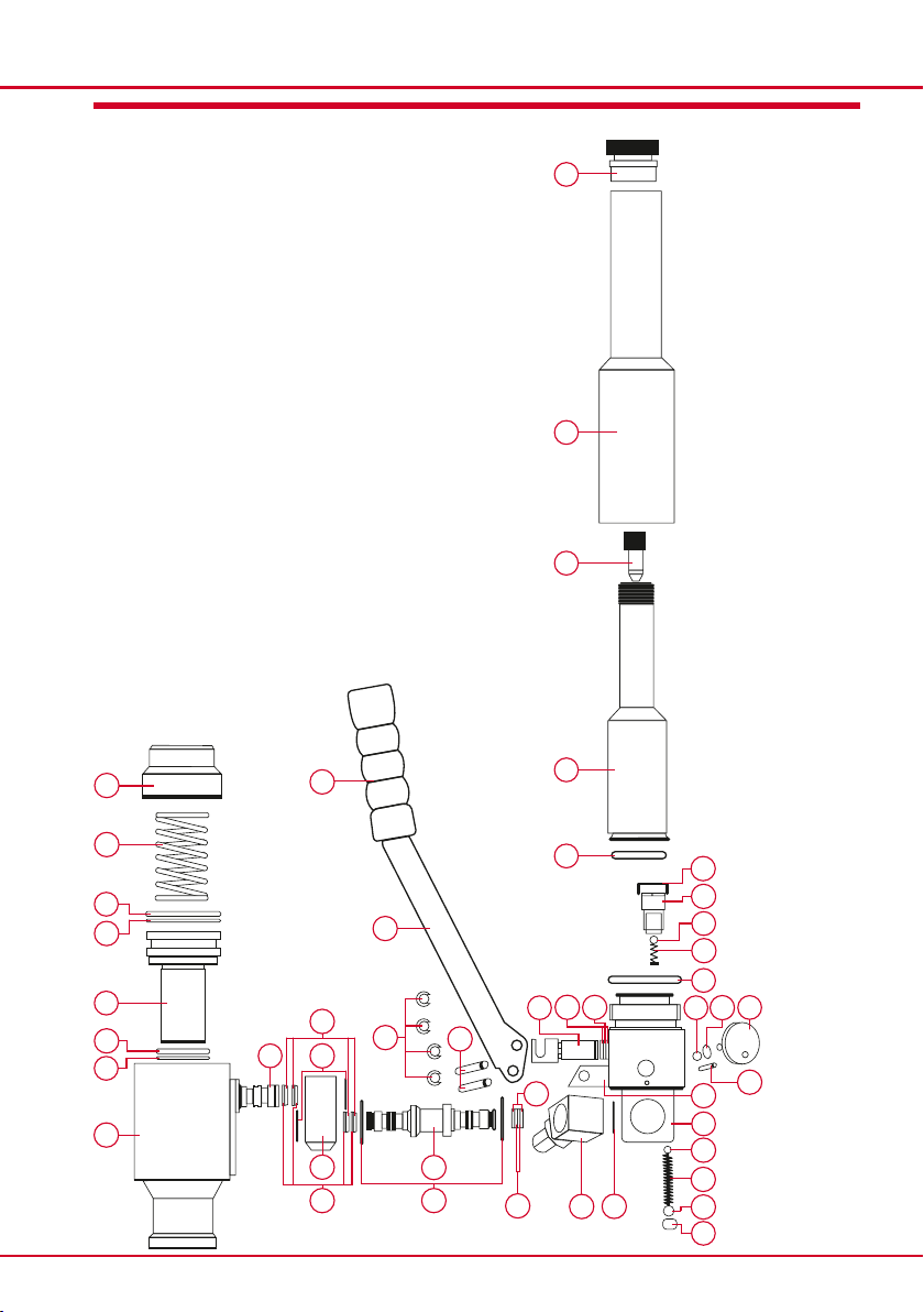
1.1 GERÄTEBESCHREIBUNG
Nummer Stück Bezeichnung Nummer Stück Bezeichnung
1 1 Hydraulikzylinder 23 1 Gegenlager für Handhebel
2 1 Stützring 24 1 Pumpenhauptteil
3 1 O-Ring 25 1 Kugel
4 1 Hydraulikkolben 26 1 Feder
5 1 O-Ring 27 1 Kugel
6 1 Stützring 28 1 Entlüftschraube
7 1 Feder 29 3 Sicherungsring
8 1 Kappe 30 1 Winkelstück
9 1 Verschlusskappe 31 1 Stützring
10 1 Schutzrohr 32 1 O-Ring
11 1 Verschlussstöpsel 33 1 Druckbolzen
12 1 Ölbehälter 34 6 Stützring
13 1 O-Ring 35 6 O-Ring
14 1 Ölfilter 36 2 Gelenkbolzen
15 1 Saugventil 37 1 Verbindungsrohr
16 1 Kugel 38 6 Blattfeder
17 1 Feder 39 4 Sicherungsring
18 1 O-Ring 40 1 Gelenkhülse
19 1 Kugel 41 1 Verbindungsrohr
20 1 O-Ring 42 1 Handhebel
21 1 Ventilrad 43 1 Gummigriff
22 1 Schwerspannstift
2. GRUNDLEGENDE SICHERHEITSHINWEISE
VORSICHT Augenverletzungen und Schnittgefahr
Lösende Metallsplitter am Stanzmaterial während und nach dem
Stanzvorgang sowie Schnittgefahr an scharfen Kanten.
▶Schutzbrille tragen.
▶Schnittschutzhandschuhe tragen.
▶Stanzabfall mit Zange entfernen.
ACHTUNG Undichtigkeit der Handhydraulik durch Fehlbedienung
Starke Pendelbewegungen führen zu Beschädigung der O-Ringe.
▶Keine starken Pendelbewegungen während Pumpvorgang
ausführen.
▶Unter Druck stehenden Hydraulikzylinder nicht drehen.
Technisch sicherer Zustand der Handhydraulik
Sicherheit und Funktion der Handhydraulik vom einwandfreien Zustand abhängig.
▶Nur passende Zubehörteile verwenden.
▶Die Handhydraulik nie eigenmächtig umbauen, verändern oder demontieren.
▶Wartung nur durch qualifiziertes Fachpersonal durchführen lassen.
▶Die Handhydraulik nur im technisch einwandfreiem Zustand betreiben.

www.hoffmann-group.com
6
3. BESTIMMUNGSGEMÄSSER GEBRAUCH
Handhydraulik zum Stanzen von gratfreien Löchern mit Blechlochern. Für Rund-, Quadrat-
und Rechtecklocher. Stanzleistung von dem zu stanzenden Material abhängig. Geeignet für
den Schaltschrank- und Anlagenbau.
4. SACHWIDRIGER EINSATZ
Handhydraulik nur für den vorgesehenen Zweck verwenden.
ɾ Keine Verlängerungen oder Umgehungsadapter an den Griff anbringen.
ɾ Maximale Kraft am Griff und Druckleistung des Werkzeuges nicht überschreiten.
5. FÜHRUNGSLOCH FÜR ZUGSCHRAUBEN
Zugschraube Gewinde* Führungsloch-⌀
M6 8 mm
M8 10 mm**
M10 12 mm**
M16 18 mm**
M20 21 mm**
*Weitere Zugschrauben-Gewinde möglich.
**Für ein Führungsloch-⌀ ab 10 mm empfehlen wir einen Stufenlochbohrer.
6. INBETRIEBNAHME
VORSICHT Augenverletzungen und Schnittgefahr
Lösende Metallsplitter am Stanzmaterial während und nach dem
Stanzvorgang sowie Schnittgefahr an scharfen Kanten.
▶Schutzbrille tragen.
▶Schnittschutzhandschuhe tragen.
▶Stanzabfall mit Zange entfernen.
6.1 STANZVORGANG VORBEREITEN
1. Führungsloch in zu stanzendes Material bohren (siehe Abschnitt 5).
6.2 ZUGSCHRAUBE UND STEMPEL EINSETZEN
1. Entsprechende Zugschraube in Hydraulikzylinder ➀ einschrauben.
2. Matrize über die in den Hydraulikzylinder ➀ eingeschraubte Zugschraube führen.
▶Distanzscheiben zwischen Hydraulikzylinder und Matrize verwenden.
3. Zugschraube durch Führungsloch führen.
4. Stempel von Gegenseite auf Zugschraube aufschrauben.
▶Stempel mit Spitze zum Stanzmaterial ausrichten.
5. Stempel mit Hand festschrauben.
▶Handhydraulik ist für Stanzvorgang vorbereitet.

www.hoffmann-group.com
7
DE
EN
FR
IT
ES
PL
83 4655
6.3 STANZVORGANG DURCHFÜHREN
1. Handventilrad durch Drehung nach rechts auf "On" stellen.
▶Handhydraulik ist geschlossen.
2. Handhebel der Handhydraulik betätigen.
▶Das Loch ist nach einigen Hüben gestanzt.
ACHTUNG Beschädigung des Blechlochers durch unkontrollierte Hübe!
▶Handhebel nach Stanzen des Ausbruchs nicht mehr betätigen.
6.4 STANZVORGANG ABSCHLIESSEN
1. Handventilrad durch Drehung nach links auf "Off" stellen.
▶Kolben des Hydraulikzylinders läuft automatisch in Ausgangsposition zurück.
2. Handhydraulik aus gestanztem Material herausnehmen.
3. Stempel von Zugschraube herunterschrauben.
4. Matrize von Zugschraube herunterführen.
▶Stanzmaterialabfall mit Zange aus Matrize entfernen.
7. TECHNISCHE DATEN
Druckleistung bis ca. 600 bar
Schwenk- und drehbarer Zylinder um 360°
Länge ohne Zugbolzen 360mm
Breite (über beide Griffe) 260mm
Gewicht 2,49kg
Maximale Kraft am Griff 356N
Kreislauftyp Geschlossen
Maximaler Betriebsdruck 44,48N
8. FEHLERBEHEBUNG
Fehler Maßnahme
Kompressionsverlust Kundenservice der Hoffmann Group kontaktieren.
Austretendes Hydrauliköl Kundenservice der Hoffmann Group kontaktieren.
9. RECYCLING UND ENTSORGUNG
Die landesspezifischen Vorschriften für Entsorgung sind anzuwenden.
Nicht im Hausmüll entsorgen.

www.hoffmann-group.com
8
IDENTIFICATION DATA
Manufacturer Hoffmann GmbH Qualitätswerkzeuge
Haberlandstr. 55
81241 Munich
Germany
Product Manual hydraulic drive
Brand HOLEX
Item number 834655 (only manual hydraulic drive)
834855 (manual hydraulic drive with gap punch set)
Version of the
user manual
01
Translation of the original instructions for use
Creation date 04/2018
Read the instructions for use, take a note of them, and store them in a safe place where they
are accessible at any time for future reference.

www.hoffmann-group.com
9
DE
EN
FR
IT
ES
PL
83 4655
1. General arrangement drawing ............................................10
1.1 Device description...................................................11
2. Fundamental safety instructions ..........................................11
3. Use for the intended purpose .............................................12
4. Use contrary to the intended purpose .....................................12
5. Guide hole ⌀ for draw bolts...............................................12
6. Preparation for use........................................................12
6.1 Preparing for the punching operation................................12
6.2 Inserting the draw bolt and punch . . . . . . . . . . . . . . . . . . . . . . . . . . . . . . . . . . .12
6.3 Performing the punching operation .................................13
6.4 Completing the punching operation .................................13
7. Technical data ............................................................13
8. Troubleshooting . . . . . . . . . . . . . . . . . . . . . . . . . . . . . . . . . . . . . . . . . . . . . . . . . . . . . . . . . .13
9. Recycling and disposal ....................................................13
CONTENT

www.hoffmann-group.com
10
1. GENERAL ARRANGEMENT DRAWING
12345678
9
11
12
14
15
16
17
18
20
19
25
26
27
28
29
29
30 32
33
34
34
35
35
36
37
38
39
40
41
43
42
10
31
21
22
23
24
13

www.hoffmann-group.com
11
DE
EN
FR
IT
ES
PL
83 4655
1.1 DEVICE DESCRIPTION
Number Unit Designation Number Unit Designation
1 1 Hydraulic cylinder 23 1 Counter bearing for hand lever
2 1 Support ring 24 1 Main pump part
3 1 O-ring 25 1 Ball
4 1 Hydraulic piston 26 1 Spring
5 1 O-ring 27 1 Ball
6 1 Support ring 28 1 Vent screw
7 1 Spring 29 3 Retaining ring
8 1 Cap 30 1 Angle clamp
9 1 Closure cap 31 1 Support ring
10 1 Protective tube 32 1 O-ring
11 1 Blanking plug 33 1 Pressure pin
12 1 Oil reservoir 34 6 Support ring
13 1 O-ring 35 6 O-ring
14 1 Oil filter 36 2 Jointed pin
15 1 Suction valve 37 1 Connecting tube
16 1 Ball 38 6 Leaf spring
17 1 Spring 39 4 Retaining ring
18 1 O-ring 40 1 Joint sleeve
19 1 Ball 41 1 Connecting tube
20 1 O-ring 42 1 Manual lever
21 1 Valve wheel 43 1 Rubber handle
22 1 Heavy-duty clamping pin
2. FUNDAMENTAL SAFETY INSTRUCTIONS
CAUTION Eye injuries and risk of lacerations
Metal splinters may fly from the material during and after the punching
operation, there is also a risk of lacerations from sharp edges.
▶Wear safety glasses.
▶Wear safety gloves.
▶Use pliers to remove the punched-out plug.
NOTICE The manual hydraulic drive may develop leaks due to mishandling
Heavy back and forth movements will damage the O-rings.
▶Do not perform heavy back and forth movements whilst pumping.
▶Do not twist the hydraulic cylinder whilst it is pressurised.
Technically safe condition of the manual hydraulic drive
The safety and correct operation of the manual hydraulic drive depends on it being in good
condition.
▶Use only suitable spare parts.
▶Do not modify, change or dismantle the manual hydraulic drive without authorisation.
▶Allow only qualified skilled personnel to perform servicing.
▶Use the manual hydraulic drive only when it is technically in good condition.

www.hoffmann-group.com
12
3. USE FOR THE INTENDED PURPOSE
The manual hydraulic drive is intended for punching burr-free holes in sheet metal. These
holes may be round, square or rectangular. The punching capacity is dependent on the mate-
rial to be punched. The drive is suitable for manufacturing control cabinets and systems.
4. USE CONTRARY TO THE INTENDED PURPOSE
Use the manual hydraulic drive only for the intended purpose.
ɾ Do not attach any extensions or bypass adaptors to the handle.
ɾ Do not exceed the maximum force at the handle and do not
exceed the pressure rating of the tool.
5. GUIDE HOLE FOR DRAW BOLTS
Draw bolt thread* Guide hole ⌀
M6 8 mm
M8 10 mm**
M10 12 mm**
M16 18 mm**
M20 21 mm**
*Other draw bolt threads may be used.
**For guide hole ⌀ from 10 mm we recommend use of a stepped hole drill.
6. PREPARATION FOR USE
CAUTION Eye injuries and risk of lacerations
Metal splinters may fly from the material during and after the punching
operation, there is also a risk of lacerations from sharp edges.
▶Wear safety glasses.
▶Wear safety gloves.
▶Use pliers to remove the punched-out plug.
6.1 PREPARING FOR THE PUNCHING OPERATION
1. Drill the guide hole in the material to be punched (see Section 5).
6.2 INSERTING THE DRAW BOLT AND PUNCH
1. Screw the appropriate draw bolt into the hydraulic cylinder ➀.
2. Guide the matrix over the draw bolt into the hydraulic cylinder ➀.
▶Insert a spacer washer between the hydraulic cylinder and matrix.
3. Feed the draw bolt through the guide hole.
4. Screw the punch on to the opposite end of the draw bolt.
▶Align the cutting edge of the punch with the material to be punched.

www.hoffmann-group.com
13
DE
EN
FR
IT
ES
PL
83 4655
5. Screw up the punch tightly by hand.
▶The manual hydraulic drive is now prepared for the punching operation.
6.3 PERFORMING THE PUNCHING OPERATION
1. Turn the manual valve wheel clockwise into the “On”position.
▶The manual hydraulic drive is now engaged.
2. Operate the manual lever of the manual hydraulic drive.
▶After a few strokes the hole will be punched.
NOTICE Damage to the hole punch by uncontrolled pump strokes!
▶Do not operate the manual lever any more once the punch has broken through.
6.4 COMPLETING THE PUNCHING OPERATION
1. Turn the manual valve wheel anticlockwise into the “Off” position.
▶The piston of the hydraulic cylinder will automatically retract to the home position.
2. Take the manual hydraulic drive out of the punched material.
3. Unscrew the punch from the draw bolt.
4. Slide the matrix down off the draw bolt.
▶Use pliers to pull the punched plug out of the matrix.
7. TECHNICAL DATA
Pressure rating up to approx. 600 bar
Pivoting and rotating cylinder by 360°
Length without draw bolt 360mm
Width (over both handles) 260mm
Weight 2,49kg
Maximum force at the handle 356N
Circuit type Closed loop
Maximum operating pressure 44,48N
8. TROUBLESHOOTING
Fault Action
Loss of compression Contact Hoffmann Group customer service.
Hydraulic oil leakage Contact Hoffmann Group customer service.
9. RECYCLING AND DISPOSAL
Comply with the national regulations for disposal.
Do not make disposal in domestic waste.

www.hoffmann-group.com
14
DONNÉES D'IDENTIFICATION
Fabricant Hoffmann GmbH Qualitätswerkzeuge
Haberlandstr. 55
81241 Munich
Allemagne
Produit Hydraulique à main
Marque HOLEX
Code article 83 4655 (hydraulique à main uniquement)
834855 (hydraulique à main avec jeu de poinçons fendus)
Version du
manuel d'utilisation
01
Traduction du manuel d'utilisation original
Date de création 04/2018
Lisez, respectez et conservez le manuel d'utilisation à des fins de consultation ultérieure, et
gardez-le toujours à disposition.

www.hoffmann-group.com
15
DE
EN
FR
IT
ES
PL
83 4655
1. Schéma d'ensemble.......................................................16
1.1 Description de l'appareil .............................................17
2. Consignes générales de sécurité...........................................17
3. Utilisation conforme à l'emploi prévu ......................................18
4. Utilisation non conforme..................................................18
5. ⌀ Trou de guidage pour vis d'assemblage .................................18
6. Mise en service ...........................................................18
6.1 Préparation du poinçonnage ........................................18
6.2 Mise en place de la vis d'assemblage et du poinçon...................19
6.3 Réalisation du poinçonnage .........................................19
6.4 Fin du poinçonnage .................................................19
7. Caractéristiques techniques ...............................................19
8. Dépannage .............................................................. 20
9. Recyclage et mise au rebut ............................................... 20
CONTENU

www.hoffmann-group.com
16
1. SCHÉMA D'ENSEMBLE
12345678
9
11
12
14
15
16
17
18
20
19
25
26
27
28
29
29
30 32
33
34
34
35
35
36
37
38
39
40
41
43
42
10
31
21
22
23
24
13

www.hoffmann-group.com
17
DE
EN
FR
IT
ES
PL
83 4655
1.1 DESCRIPTION DE L'APPAREIL
Numéro Pièce Désignation Numéro Pièce Désignation
1 1 Vérin hydraulique 23 1 Contre-palier pour levier à main
2 1 Bague d'appui 24 1 Corps de pompe
3 1 Joint torique 25 1 Bille
4 1 Piston hydraulique 26 1 Ressort
5 1 Joint torique 27 1 Bille
6 1 Bague d'appui 28 1 Vis de purge
7 1 Ressort 29 3 Circlip
8 1 Capuchon 30 1 Pièce d'angle
9 1 Capuchon 31 1 Bague d'appui
10 1 Tube de protection 32 1 Joint torique
11 1 Bouchon 33 1 Vis de serrage
12 1 Réservoir d'huile 34 6 Bague d'appui
13 1 Joint torique 35 6 Joint torique
14 1 Filtre à huile 36 2 Vis articulée
15 1 Soupape d'aspiration 37 1 Tube de raccordement
16 1 Bille 38 6 Ressort à lames
17 1 Ressort 39 4 Circlip
18 1 Joint torique 40 1 Douille articulée
19 1 Bille 41 1 Tube de raccordement
20 1 Joint torique 42 1 Levier
21 1 Molette 43 1 Poignée en caoutchouc
22 1 Goupille fendue

www.hoffmann-group.com
18
2. CONSIGNES GÉNÉRALES DE SÉCURITÉ
ATTENTION Blessures oculaires et risque de coupure
Détachement d'éclats métalliques au niveau du matériel à poinçonner
pendant et après le poinçonnage, ainsi que risque de coupure dû aux
arêtes vives.
▶Porter des lunettes de protection.
▶Porter des gants de protection anti-coupures.
▶Retirer les chutes de poinçonnage à l'aide d'une pince.
IMPORTANT Défaut d'étanchéité de l'hydraulique à main en raison d'une
utilisation incorrecte
Des mouvements pendulaires forts entraînent un endommagement
des joints toriques.
▶Ne pas effectuer de mouvements pendulaires forts pendant
le pompage.
▶Ne pas tourner le vérin hydraulique sous pression.
Etat techniquement sûr de l'hydraulique à main
La sécurité et le bon fonctionnement de l'hydraulique à main dépendent de son parfait état.
▶Utiliser uniquement des accessoires adaptés.
▶Ne jamais transformer, modifier ou démonter l'hydraulique à main de sa propre initiative.
▶Confier l'entretien uniquement à un personnel technique qualifié.
▶Utiliser uniquement l'hydraulique à main si elle se trouve dans un parfait état technique.
3. UTILISATION CONFORME À L'EMPLOI PRÉVU
Hydraulique à main pour le poinçonnage de trous sans bavures à l'aide de poinçons. Pour
trous ronds, carrés et rectangulaires. Les résultats de poinçonnage dépendent du matériel à
poinçonner. Convient pour la construction d'équipements et d'armoires électriques.
4. UTILISATION NON CONFORME
Utiliser uniquement l'hydraulique à main aux fins prévues.
ɾ Ne pas fixer de rallonges ni d'adaptateurs à la poignée.
ɾ Ne pas dépasser la force maximale au niveau de la poignée ni
la capacité de pression de l'outil.

www.hoffmann-group.com
19
DE
EN
FR
IT
ES
PL
83 4655
5. TROU DE GUIDAGE POUR VIS D'ASSEMBLAGE
Filetage de vis d'assemblage* ⌀ trou de guidage
M6 8 mm
M8 10 mm**
M10 12 mm**
M16 18 mm**
M20 21 mm**
*D'autres filetages de vis d'assemblage sont possibles.
**Pour un ⌀ de trou de guidage à partir de 10 mm, nous recommandons l'utilisation d'un foret étagé.
6. MISE EN SERVICE
ATTENTION Blessures oculaires et risque de coupure
Détachement d'éclats métalliques au niveau du matériel à poinçonner
pendant et après le poinçonnage, ainsi que risque de coupure dû aux
arêtes vives.
▶Porter des lunettes de protection.
▶Porter des gants de protection anti-coupures.
▶Retirer les chutes de poinçonnage à l'aide d'une pince.
6.1 PRÉPARATION DU POINÇONNAGE
1. Percer un trou de guidage dans le matériel à poinçonner (voir section 5).
6.2 MISE EN PLACE DE LA VIS D'ASSEMBLAGE ET DU POINÇON
1. Visser la vis d'assemblage correspondante dans le vérin hydraulique ➀.
2. Amener la matrice sur la vis d'assemblage vissée dans le vérin hydraulique ➀.
▶Utiliser des entretoises entre le vérin hydraulique et la matrice.
3. Insérer la vis d'assemblage dans le trou de guidage.
4. Visser le poinçon sur la vis d'assemblage par le côté opposé.
▶Aligner le poinçon avec la pointe sur le matériel à poinçonner.
5. Visser fermement le poinçon à la main.
▶L'hydraulique à main est prête pour le poinçonnage.
6.3 RÉALISATION DU POINÇONNAGE
1. Placer la molette sur "On" en la tournant vers la droite.
▶L'hydraulique à main est fermée.
2. Actionner le levier de l'hydraulique à main.
▶Le trou est poinçonné après quelques courses.
IMPORTANT Endommagement du poinçon par des courses non contrôlées!
▶Cesser d'actionner le levier une fois le poinçonnage terminé.

www.hoffmann-group.com
20
6.4 FIN DU POINÇONNAGE
1. Placer la molette sur "Off" en la tournant vers la gauche.
▶Le piston du vérin hydraulique revient automatiquement dans sa position initiale.
2. Retirer le matériel poinçonné de l'hydraulique à main.
3. Dévisser le poinçon de la vis d'assemblage.
4. Retirer la matrice de la vis d'assemblage.
▶Retirer les chutes de poinçonnage hors de la matrice à l'aide d'une pince.
7. CARACTÉRISTIQUES TECHNIQUES
Pression Jusqu'à env. 600 bars
Vérin basculant et pivotant Sur 360°
Longueur sans boulons d'assemblage 360mm
Largeur (sur les deux poignées) 260mm
Poids 2,49kg
Force maximale au niveau de la poignée 356N
Type de boucle Fermée
Pression de service maximale 44,48N
8. DÉPANNAGE
Erreur Mesure
Perte de compression Contacter le service clientèle de Hoffmann Group.
Fuite d'huile hydraulique Contacter le service clientèle de Hoffmann Group.
9. RECYCLAGE ET MISE AU REBUT
Respecter les règlementations nationales en matière de mise au rebut.
Ne pas jeter dans les ordures ménagères.
Table of contents
Languages:
Popular DC Drive manuals by other brands

Applied Motion Products
Applied Motion Products STAC6-Q-H Quick setup guide

MAIMAN ELECTRONICS
MAIMAN ELECTRONICS SF6060 Datasheet and User Manual

Bosch
Bosch BDU490P Original operating instructions

Saci
Saci Vari Pro manual

Bosch
Bosch Active Line Plus BDU 350 Original operating instructions

Minolta
Minolta MD-90 owner's manual

M-Elec
M-Elec ADB-2F30BA instruction manual

KEBCO
KEBCO COMBIVERT F5 Reference manual

Becker
Becker C01 Assembly and operating instructions

AutomationDirect
AutomationDirect DURApulse GS20X Series quick start guide

KEBCO
KEBCO COMBIVERT F6 series Instructions for use

Kieback&Peter
Kieback&Peter DSY/4 Product description