Aumuller FVM2 Training manual

FVM2 - LOCKING DRIVE MINI FOR WINDOWS
according to Machinery Directive 2006/42/EC (annex VI)
Assembly and Commissioning
Instructions

2
Assembly Instruction
FVM2
CONTENTS
08
07
06
05
04
03
02
01
Abbreviations
Target Groups
Warning and Safety Symbols
Intended Use
Safety Instructions
Data sheet FVM2
Data sheet FVM2 with specic application
Explanations on the product label
Determination of locking points
INSTALLATION STEP 1: Inspection before the installation
INSTALLATION STEP 2: Installation prerequisite and Installation preparation
INSTALLATION STEP 3A:Hole layouts (Application examples)
INSTALLATION STEP 3B:Hole layouts for locking drive FVM2
INSTALLATION STEP 3C:Milling layouts for concealed mounting inside proles
INSTALLATION STEP 4: DIP switches setting (moving direction and the locking stroke)
INSTALLATION STEP 5: Assembly the locking drive
INSTALLATION STEP 6: Manual unlocking mechanism
INSTALLATION STEP 7: Electric Connection
INSTALLATION STEP 8: Supply lines of the Control Unit to the drives
INSTALLATION STEP 9: Safety check and Test run
Troubleshooting, Service and Repair
Maintenance and Modication
Removal and Disposal
Liability
Warranty and After-Sales Service
3 - 8
9 - 11
12
13 - 14
15 - 17
17 - 23
24 - 28
29

3
Assembly Instruction
FVM2
PRELIMINARY REMARK
Once the assembly and commissioning
has been completed, the installer of a
machine „power-operated window and door“ shall hand
these instructions over to the end-user. The end-user shall
store these instructions in a safe place for further reference
and use, if required.
!
WARNING
Index of abbreviations
These abbreviations are used consistently throughout these assembly
& operating instructions. Unless stated differently, all dimensions indi-
cated in this document are in mm. General tolerances in accordance
with DIN ISO 2768-m.
A drive
AK connection cable / drive cable
AP cover cap
BD hinge
Fxxx casement bracket
FAB overall width of casement
FAH overall height of casement
FG casement weight
FL casement
FÜ casement overlap
HSK main closing edge
Kxxx frame bracket
L construction lenghth of drive
MB central hinge
NSK side closing edge
RA frame
RAB overall width of frame
RAH overall height of frame
SL snow load
opening direction
ABBREVIATIONS
Failure to comply with the warning notes results
in irreversible injuries or death.
Failure to comply with the warning notes can re-
sult in irreversible injuries or death.
Failure to comply with the warning notes can re-
sult in minor or moderate (reversible) injuries.
Failure to comply with the warning notes can lead
to damage to property.
WARNING AND SAFETY SYMBOLS IN THESE IN-
STRUCTIONS:
The symbols used in the instructions shall be strictly observed and have
the following meaning:
Caution / Warning
Danger due to electric current.
Caution / Warning
Risk of crushing and entrapment during device operati-
on (is provided as a sticker with the drive).
Attention / Warning
Risk of damage to / destruction of drives and / or
windows.
!
WARNING
!
DANGER
!
CAUTION
NOTE
!
These instructions are intended for trained personnel
and operators of systems for natural smoke ventilation
(NRA / SHEV) (natural smoke exhaust system / smoke and
heat exhaust system) and natural ventilation via windows,
who are knowledgeable of operating modes as well as the
remaining risks of the system.
This device is not intended for use by per-
sons (including children) with physical,
sensory or mental limitations or lacking experience and / or
knowledge, unless they are supervised by a person who is
responsible for the safety or were instructed by him on the
usage of this equipment. Children should be supervised to
ensure that they are not playing with this device.
Cleaning and operator’s maintenance may not be per-
formed by children without supervision.
TARGET GROUP
!
WARNING
RA
FL
FAB
FA H
BD
HSK
NSK
NSK
RAB
RAH
01

4
Assembly Instruction
FVM2
PRELIMINARY REMARK
01
By attaching a drive to a movable
element of the window a so-called
“power-operated window” is created
which, according to the Machinery
Directive 2006 / 42 / EG, represents a
machine.
Pay attention to possible hazards on
tilting or rotating windows, whose
secondary closing edges are located
at less than 2,5 m installation height
above the oor, under consideration of
the Control Unit and usage!
NOTE
!
WARNING
INTENDED USE
Area of application / Scope of application
This drive is intended for the electromotive locking and
unlocking of windows in facade and roof areas.
The main task of this product, in combination with
a window and a suitable external control unit, is to
evacuate hot smoke and combustion gases in case
of re, to safe human lives and protect material
assets. Furthermore, with the electromotive operated
window and a suitable external control unit, the natural
ventilation of the building can be ensured.
Intended use according
The drive is intended for stationary installation and
electrical connection at the window as part of a building.
The drive is in combination with an external Control Unit
(e.g. from AUMÜLLER) released for its proper use at a
power-operated window for the following use:
• Application for natural ventilation
with an installation height of the drive and
the bottom side of sash of at least 2,5 m above
the oor, or
with an opening width at the HSK of the driven
part of < 200 mm by a simultaneous speed of
< 15 mm/s at the HSK in closing direction.
• Application as NSHEV (natural smoke and heat
exhaust ventilator(s) for ventilation without dual
purpose for ventilation in accordance with EN12101-2.
The manufacturer of the power-operated window has
to carry out a risk assessment for all other applications
independently - at the installation-site of the window.
The need for a risk assessment at the installation-site
due to the reasonably foreseeable misuse.
A risk assessment in accordance with the Machinery
Directive 2006 / 42 / EG for the usage of the power-
operated window for natural ventilation is absolutely
necessary under the following conditions:
• the installation height of the drive and lower edge
of casement < 2,5 m above the oor
and one of the following conditions:
• the opening width at the HSK > 200 mm, or
• the closing speed at the HSK is > 15 mm/s, or
• the opening speed at the HSK is > 50 mm/s, or
• the closing force at the HSK is > 150 N
The following ow chart can be applied, which also includes
the protective measures in accordance with EN 60335-2-
103/2016-05.
We as manufacturers are well aware of our duties and
responsibilities regarding the development, manufactu-
ring and placing of safe window drives on the market and
consistently implement them. Ultimately, however, we have
no direct inuence on the usage of our drives. Therefore,
as a precaution, we point out the following:
• The constructor or his agent (architect, specialist
planner) are obligated to evaluate the
hazards to persons, outgoing from the usage,
installation position, opening parameters and from the
external Control Unit of the power operated window,
already in the planning phase and to establish
necessary protective measures.
• The constructor / manufacturer of the machine
“power-operated window” must implement the
planned protective measures at the installation-site
or, if not yet established, determine them by it´s
own responsibility and detect or minimize possible
remaining risks.

5
Assembly Instruction
FVM2
PRELIMINARY REMARK
01
Casement data
Facade: bottom-hung window, top-hung-win-
dow, side-hung window.
Roof: roof window / sky light.
Opening direction: inward opening, outward opening.
Prole material: aluminum, steel, plastic or wood.
When inspecting the drives for conformity with on-site
requirements the following items must be observed:
• total weight of casement (glass + frame),
• casement size (FAB x FAH),
• driving force and stroke,
• mounting site at the window frame and casement
frame.
Hazard analysis according to DIN EN 60335-2-103
Contact-free anti-trap protection
(20.ZAA.8.1)
Passive infra-red and active light sensors
or
pressure mats
Contact-based anti-trap protection
(20.ZAA.8.2)
Pressure-sensitive safety switch strips
or
Motor current monitoring systems
(internal and external)
Hold-to-run switch:
stops movement at HSK < 20 mm
at a closing force of > 150 N at HSK
(20.ZAA.5)
Operating element in
direct range of vision:
a.) Key switch or
b.) other switch,
then: installation > 1,5 m,
inaccessible for public
(7.12.1)
Keep people away during closing!
Declaration of Conformity
power operated window
+ CE label
!
CAUTION
Protection devices
!
CAUTION
Use of the drive
NSHEV according to
EN12101-2 without
dual purpose for ventilation
NSHEV according to
EN12101-2 with
dual purpose for ventilation
(1.Z.109)
Natural ventilation
Installation height of drive and lower
edge of casement: > 2,5 m above oor
(ZAA.20.2)
Opening at HSK: < 200 mm and
Speed at HSK:
CLOSE <15 mm/s / OPEN < 50 mm/s
(20.ZAA.2)
Yes
Yes
No
No
No
risc assessment
required
Observe danger at NSK
< 2,5 m above oor!
!
CAUTION
Keep people away during closing!
!
CAUTION
Environment with children /
vulnerable people
The information in the brackets
refer to the chapters of DIN EN 60335-2-103.
Risk analysis according to the
Machinery Directive required

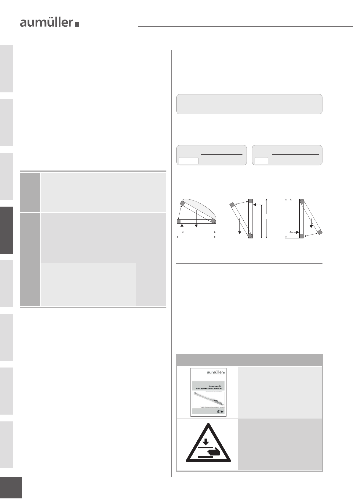
6
Assembly Instruction
FVM2
SAFETY INSTRUCTIONS
01
Danger spots by crush and shear points
Side-hung Bottom-hung Roof windows / skyskylight domes Louvre windows
Danger spots: crush and shear points according to DIN EN 60335-2-103
NOTE
NOTE
!
WARNING
!
WARNING
!
All devices must be permanently protected
from dirt and moisture, if the drive is not
explicitly suitable for use in wet areas (see
technical data).
Area of application
The drive shall only be used according to its intended use.
For additional applications consult the manufacturer or his
authorized dealer.
Mounting material
The required mounting material must to t with the drive
and occurring load and, if necessary, supplemented.
Installation
These instructions address expert and safety-conscious
electricians and / or qualied personnel knowledgeable in
electrical and mechanical drive installation.
Always check whether the system complies with current
legal regulations. Special attention must be paid to the
opening width, the opening area, the opening time and the
opening speed of the window, the temperature range of
the drives / external devices and cables as well as the cross
section of the connecting cables as function of the cable
length and power consumption.
All specications for installation must be checked indepen-
dently and, if necessary, adjusted at the installation-site.
The connection assignment, the electrical supply data (see
machine plate) and performance limits (see technical data)
as well as the mounting and installation instructions of the
drive must be strictly observed and adhered to!
Do not reach into the window rabbet or the operating
element (chain or spindle) during installation and opera-
tion! Ensure that, based on the installation position and
the opening movement of the casement, persons cannot
be trapped between the driven part of the window and
surrounding xed components (e.g. wall).
SAFETY INSTRUCTIONS
It is important to follow these instruc-
tions for the safety of persons. These
instructions shall be kept in a safe place
for the entire service life of the products.
Risk of crushing and entrapment!
Window can close automatically!
The integrated load cut-off stops the
opening-drive during closing and opening
when the drive is overloaded.
The compressive force is absolutely
sufcient to crush ngers in case of
carelessness.
Do not misuse the drive for other
applications! Do not allow children to
play with this drive or its regulating
and / or control units, including the
remote control!
The safe operation, avoidance of injury to
persons and damage to property, as well
as risks, is only guaranteed by proper
installation and setting according to
these installation instructions.
Before installing the drive, check whether
the casement is in good mechanical con-
dition, the weight in balance and whether
it opens and closes easily!
Never connect 24 V DC drives to 230 V AC
mains voltage!
Danger to life!

7
Assembly Instruction
FVM2
SAFETY INSTRUCTIONS
0101
!
WARNING
!
WARNING
Crush and shear points
To avoid injuries, crushing and shear points between
casement and frame must be secured against entrapment
up to an installation height of 2,5 meters above the
oor with appropriate measures. This can be achieved e.g.
by using contact-based or contactless protective devices
against entrapment, which stop the motion through cont-
act or through interruption by a person. At a force higher
than 150 N at the main closing edge the motion must stop
within 20 mm. A warning symbol at the opening element
must indicate this clearly.
Unintentional or independent opening or falling
Casements are to be hinged or secured such way that in
case one of the mounting elements fails it will not crash /
slam down or move in an uncontrolled manner by e.g. using
double suspensions, safety scissors, casement stays.
Tilting windows shall be equipped with safety scissors or
similar devices to avoid damages and risks of injury for
persons through improper installation and operation. The
safety scissors must be adjusted to the opening stroke of
the drive (see technical data) to avoid blocking.The opening
width of the safety scissors must be bigger than the drive
stroke.
Routing cables and electrical connection
Routing or installing of electrical cables and connections
may be performed only by specialist companies. Never
operate drives, control units, operating elements and
sensorsat operating voltages and connections contrary
to the specications of the manufacturer.
All relevant instructions shall be observed for the in-
stallation, specically:
• VDE 0100 Setting up high-voltage systems up to 1000 V
• VDE 0815 Wiring cables
• Specimen Guideline on Conduits German designation
(MLAR).
The types of cable, cable lengths and cross-sections shall
be selected in accordance with the manufacturer’s technical
data. If necessary, the cable types shall be coordinated with
the competent local authorities and energy supply com-
panies. Low-voltage lines (24 V DC) shall be routed
separate from the high-voltage lines. Flexible cables may
not be ush-mounted. Freely suspended cables shall be
equipped with strain reliefs.
Clamping points shall be checked for tightness of threa-
ded connections and cable ends. Access to junction boxes,
clamping points and external drive control boxes shall be
ensured for maintenance work.
Damaged mains supply lines of drives
with plug connectors may only be re-
placed by the manufacturer or qualied
service / maintenance personnel!
Power cables which are xed to the drive
casing cannot be replaced. If the cable is
damaged the device must be scrapped!
The movable casement must be secured
against unintentional or independent
opening as well as falling down.
All-pole disconnecting devices shall be instal-
led in the permanent electrical installation or
external Control Unit for the drive.
The mains supply lines 230 V / 400 V AC shall
be protected separately!
24V DC drives may only be connected to
power supply sources that comply with SELV
specications.
Cables must be laid such way that they can-
not be sheared off, twisted or bent during
operation. Drive cables laid inside window
proles must be protected by insulating
tubes with a sufcient temperature resistance.
Through holes shall be equipped with cable
sleeves!
safety scissors
In the case of tandem / multiple opera-
tion of drives connected in series, the
cross-section of the connection cable
must be checked autonomously, depen-
ding on the total current consumption of
the drive system.
NOTE

8
Assembly Instruction
FVM2
SAFETY INSTRUCTIONS
01
NOTE
NOTE
Post warning signs!
Other persons must be kept away from
the casement when a hold-to-run switch
(push button) is operated or when a
window, which has been opened by a
smoke and heat exhaust system, is clo-
sing!
The operating element of hold-to-run
switches must be installed within di-
rect view from the window, but apart
from moving elements. If the switch is
not a key-operated switch it must be
installed at a minimum height of 1,5 m
and inaccessible to the public!
Do not allow children to play with
permanently mounted control devices
and keep remote controls out of reach
for children!
!
CAUTION
!
CAUTION
!
CAUTION
During cleaning, maintenance work and while
exchanging parts the drive must be comple-
tely disconnected from the power supply and
secured against unintentional reactivation.
During cleaning and maintenance works and while
exchanging parts, all poles of the drive must be dis-
connected from the power supplyand and secured
against unintentional reactivation.
Replacement parts, fasteners and controls
The drive shall only be operated with control devices from
the same manufacturer. There is no liability, warranty or
customer service if third-party parts are used. Exclusively
original replacement parts of the manufacturer shall be
used for mounting elements or expansions.
Ambient conditions
The product may not be subjected to impacts or falls, or
to vibrations, moisture, aggressive vapors or other harmful
environments, unless the manufacturer released it for one
or more of these environmental conditions.
• Operation:
Ambient temperature: -5 °C … +60°C
Relative humidity: < 90% less 20°C;
< 50% less 40°C;
no formation of condensation
Observe temperature range during
installation!
• Transport / Storage:
Storage temperature: -5°C … +40°C
Relative humidity: < 60%
Accident prevention regulations and workmen’s
compensation insurance guidelines
For work on or in a building or building part the provisi-
ons and instructions of the respective accident prevention
regulations (local workmen’s compensation insurance
guidelines) shall be observed and adhered to.
Declaration of Conformity and of Incorporation
The drive is manufactured and inspected in accordance with
European guidelines. The respective Declaration of Con-
formity and of Incorporation is on hand.
In case that the use of the drive differs from the in-
tended use, a risk evaluation for the power operated
window shall be performed and a Declaration of Con-
formity according Machinery Directive 2006 / 42 / EG
issued.
!
WARNING
Do not actuate the drive or the case-
ment when repair or re-setting works are
performed!
Commissioning, operation and maintenance
After the installation and after each modication in the set
up all functions shall be checked with a trial run. It shall
be ensured that drive and casement are set correctly and
that security systems, if available, are functioning properly.
After the installation of the system is completed the
end-user shall be introduced to all important opera-
ting steps. If necessary, he must be advised of all remaining
risks / dangers.
The end-user shall be specically instructed that no
additional forces, except pushing and pulling forces in the
opening and closing direction of the casement, may be
applied to the spindle, chain or lever of the drive.

9
Assembly Instruction
FVM2
DATA SHEET
02
DATA SHEET FVM2
Application: natural ventilation, SHEV, ferralux®-NSHEV
Surface or concealed mounting inside proles
Locking plate (8 mm) on top or bottom mountable
Locking position selectable: right / left
Locking stroke selectable: s = 36 mm or 17 mm
Manual unlocking mechanism
Options
Special functions programmable
M-COM suitable internal Control Electronics and sequence control for drives S3 /S12
Star wiring
Current of the drives does not run over FVM2
Sequence control via communication wire
TECHNICAL DATA
UNRated voltage 24V DC (19 V ... 28 V)
IACut-off current ~ 0,4 A
PNRated power 10 W
IDCurrent of opening drives non relevant
DC Duty cycle 5 cycles (ED 30 % - ON: 3 min. / OFF: 7 min.)
Protection rating IP 32
Ambient temperature range -5 °C ... +60 °C
FAPushing / Pulling force max. ~ 600 N
FLBreaking fore max. ~ 1000 N
t Housing / Locking plate stainless steel
Connecting cable non-halogen, grey 3 x 0,5 mm², ~ 3 m
Speed 1,9 mm/s
s Stroke ~ 36 mm (± 2) or 17 mm (± 1)
L Dimensions 473 x 25 x 25 mm
Sound pressure level
≤ 70 dB (A)
ACCESSORIES
Hardware set
B23 Application
Surface mounting on the
main/side closing edge of the
window frame prole of inward
opening windows. Adjustable
locking bolt for compensation of
the prole overlapp
FÜ 0 - 25 mm
NOTE: Only one locking point!
Part.-No. 514081
Material / Finish
T-locking plate (aluminium)
Locking bracket VW
(stainless steel)
Feature / Equipment
1x T- locking plate
1x locking bracket B18
Locking plate
B24 Application
Locking plate 6 mm alternative
to the locking plate 8 mm due
to limited rebate space.
Part.-No. 514066
Material / Finish
stainless steel
Feature / Equipment
37 x 30 x 6 mm
37
5,5
30
25
10
34
12,5
7
205
max. 113
2 x 17 ±1
473
11
7
s=36 ±2

10
Assembly Instruction
FVM2
DATA SHEET FVM2
02
ORDER DATA
s [mm] L [mm] Version Finish PU / pcs. Part.-No.
17 – 36 473 FVM2 E6/C-0 1 514062
OPTIONS
Special model PU / pcs. Part.-No.
Drive housing painted/powder coated in other RAL colours
Lump sum for coating 516030
Specify at order stage:
1 – 20 516004
21 – 50 516004
51 – 100 516004
up 101 516004
Extra length connecting cable:
5m – non-halogen, grey – 3 x 0,5 mm² 501034
10 m – non-halogen, grey – 3 x 0,5 mm² 501036
Microprocessor programming S12
Special functions 524180
Optional accessories PU / pcs. Part.-No.
M-COM Conguration module for synchronised multi-drive systems 1 524177
serial number
symbols see
„Technical data“ article reference
number
EXPLANATIONS ON THE PRODUCT LABEL
The product label informs about:
• manufacturer‘s address
• article reference number and name
• technical caracteristics
• date of manufacturing with rmware version
• certications
• serial number
Never install and operate damaged
products.
In the event of any complaints, please indicate the
product serial number (SN) (see product label).
Product designation certications
date of manufacturing
with rmware version
Date: 19W01 V:2.0
SN: xxxxxxxxx
Art.-Nr.: xxxxxx
Exemplary representation
i
-5°C
+60°C
86672 Thierhaupten
Tel.: +49 8271 8185-0
Made in Germany
XXX
window drive
FA: xxx N
S: xxx mm
IP: xxxUN: xxx V
DC: xxx cyclesIN: xxx A

11
Assembly Instruction
FVM2
SPECIFIC APPLICATIONS
Friction hinged window – Schüco AWS102
FVM2 Part.-No. 514063
SW-V2 (software) with M-COM suitable internal load dependent cut-off switch and
sequence control for drives S3 /S12 (star wiring, drive current does not run over FVM2,
sequence control via communication wire)
Concealed mounting inside proles
Pre-assembled T-form coupling adapter
Locking position selectable: right / left
Locking stroke selectable: s = 36 mm or 17 mm
Manual unlocking mechanism
Fixing accessories 2x spacer plate 25x12x10 mm, aluminium
T-Locking plate stainless steel
Connecting cable non-halogen, grey 3 x 0,5 mm², ~ 3 m
DATA SHEET
02

12
Assembly Instruction
FVM2
PREPARING ASSEMBLY
03
The number of locking points depends on:
• object-specic requirements
• processing guidelines and authorized ranges of
application of the manufacturer
• EN 12102-2 NRWG (depending of prole group
and wind load classication WL)
• EN 12207 Air permeability
• EN 12208 Driving rain tightness
• EN 12210 Resistance to wind load
• EN 1627 Burglar resistance
• EN 14351-1 Window or door standard
• DIN 1991-1-3 Snow loads
• DIN 1991-1-4 Wind loads
Locking points are centers / axes of the following com-
ponents: casement hinges / stays (BD), sealing points of
the locking system, application points of directly actuating
drives (force transmission axes at 90° to the casement
prole, with closed window).
Drives used in SHEV mounting devices such as: RWA 1000,
RWA 1050, RWA 1100 are not included in the locking points.
Free prole lengths are effective distances between two
locking points. Corner and edge distances shall be cal-
culated as straight lines.
Only the worst case with secured values and
application ranges must serve as a basis.
!
FL
RA
HSK
free prole length free
free prole length
prole length
freelength
free prole
prole length
free prole
length
NSK
BD
Locking point
FAB
FAH
DETERMINATION OF LOCKING POINTS
Free prole lengths
between two locking points
Free prole length for Ix4-values
of the window casement proles
20-34 cm435-50 cm451-55 cm456-99 cm4
Static wind slipstream loads
on the SHEV - according to EN 12101-2.
WL
1000
1300 mm 1500 mm 1700 mm 1900 mm
WL
1500
1200 mm 1400 mm 1600 mm 1800 mm
WL
2000
1100 mm 1275 mm 1450 mm 1650 mm
WL
2500
900 mm 1025 mm 1150 mm 1275 mm
WL
3000
800 mm 900 mm 1000 mm 1100 mm
Values apply only for AUMÜLLER ferralux NRWG.
NOTE
The number of locking points or the
free prole length between two locking
points are described into the respective
system documents of the window prole.
This information must be adhered.
The requirements for the tightness of the
windows according to EN 14359-1 must
be observed!

13
Assembly Instruction
FVM2
There must not be any chamber gear in the
tting!
INSTALLATION STEP 1: INSPECTION BEFORE THE INSTALLATION
Test kit for drives
Order number:
Application:
Supply voltage:
Drive types:
Drive current:
Display:
Ambient temperature:
Plastic housing:
Weight:
Feature / equipment:
533981
Test kit to check running direction and
communication of drives 24V DC or
230V AC (including batteries)
230V AC
24V DC / 230V AC
max. 3 A
drive current, battery charge
-5 °C ... + 40 °C
250 x 220 x 210 mm
approx. 3,6 kg
Control elements: 2 switches + 1 button
NOTE
We recommend the use of our test kit for
the inspection of drives with the rated
voltage 24V= / 230V~ (see table below).
Damaged products may not be operated
under any circumstance.
It is imperative that the sufciently
mechanical stiffness of the fastener type
as well as of the swivel range of the drive
is observed.
If this is not guaranteed another type of
fastening or another type of drive must
be selected.
!
The support surface of the frame brackets or
casement brackets must rest completely on
the window or frame prole. There must be
no tilting of the fastening elements during
extension and retraction of the drives. A
safe and solid fastening must be ensured
at the window prole.
Storage of drives at the construction-site
Protective measures against damages, dust, moisture or
contamination shall be taken. Store drives intermediately
only in dry and well ventilated rooms.
Inspection of drives before installation
Check drives and window before installation for good
mechanical condition and completeness. The chains / spind-
les of the drives must be extendable or retractable easily.
The casement must run smoothly and the weight must be
in balance.
The test procedure of drives may only be performed on a
non-slip and secured mat or a test xture. During the test
run the test element must not be interfered with. The test
my only be conducted by or under the supervision of expert
personnel.
Inspection of the intended use
The planned use of the drive must be checked for com-
pliance with its intended use. If used otherwise the liability
and warranty claim expires.
Predictable misuse
It is imperative that foreseeable misuse of drives is avoided!
Here are a few examples:
• do not connect 24 V DC drives to a 230 V AC mains
voltage,
• observe synchronous run and sequence control by drives
with multiple interconnection,
• use drives only indoors,
• avoid additional force inuences, e.g. transverse forces.
Testing mechanical requirements
Prior to the start of the installation check whether :
• the support surface and the prole static for the load
transmission is sufcient,
• a support construction for the secure fastening of the
drives is required,
• cold bridges (thermal separation) are avoidable at
action points,
• possibly there is sufcient space for the swivel
movement of the drive.
If not, counter measures must be taken!
!
CAUTION
!
WARNING
Important instructions for a safe instal-
lation. Observe all instructions, wrong
installation may result in serious injury!
PREPARING ASSEMBLY
04
14
Assembly Instruction
FVM2
Accessories for locking drive
Assembly and Commissioning
Instructions
Warning sign sticker
„Risk of entrapment“ (1x)
04
Tools required
• Marker,
• Grains,
• Hammer,
• Knife,
• Screwdriver (cross, Torx),
• Hexagonal wrench,
• Torque wrench,
• Power drill,
• Threadlock adhesive,
• possibly a tool for blind rivet nuts.
Scope of delivery:
Prior to assembly, check items quantity in the delivery for
completeness.
Check window data on site
• Measure FAB and FAH.
• Check / calculate weight of casement.
If unknown, it can be determined approximately with
the following formula:
• Check / calculate the required drive force and compare
with drive data . If unknown, it can be determined
approximately with the following formula:
a= Distance of action point to hinges
F= Drive force
s= Stroke
weight) [kg] [m] [m] [mm] frame
share
glass-
density
G (Casement = FAB *FAH *Glass thickness * 2,5 *1,1
F[N] =
Facade Roof
F[N] =
5,4 *G[kg] *s[m] 5,4 *G[kg] *FAH [m]
a[m] a[m]
INSTALLATION STEP 2: INSTALLATION PREREQUISITE AND INSTALLATION PREPARATION
The following conditions must be fullled for the instal-
lation of the drives so they can be properly assembled with
other parts and constructed to a complete machine at the
window without impairing the safety and health of persons:
1. The design of the drive must fulll the requirements.
2. The fastening accessories (casement brackets or
frame brackets) must t the window prole; the
prole-dependent hole lay-out must be complied with.
3. The space required for the installation of the drive on
the frame and casement prole must be sufcient.
4. The window must be in perfect mechanical condition
before the installation. It should open and close easily.
5. The fastening material for the installation of the drive
must t the window material (see table).
PREPARING ASSEMBLY
04
a
a
a
G
G
s
s
s
FAH
G
F
FF
FAH
FAH
Wood windows
Wood screws:
i.e. DIN 96, DIN 7996, DIN 571
round head with slot,
round head with cross,
hex head,special type
steel, stainless steel,
aluminum windows
Self-tapping screws, thread screws,
sheet-metal screws
i.e. ISO 4762, ISO 4017, ISO 7049 , ISO 7085, DIN 7500
cylinder head with hex socket, internal serration (Torx),
Phillips head or external hex head
blind rivet nut
plastic windows
Screws for plastic
i.e. DIN 95606, DIN 95607, ISO 7049,
ISO 7085, DIN 7500
round head with cross, external hex head,
Torx
Recommendation:
if possible, screw
through two cavity
webs

15
Assembly Instruction
FVM2
HOLE LAYOUTS
Hole layouts (Application examples)
Concealed mounting inside proles
outward opening windows
Concealed mounting inside proles
outward opening windows
Concealed mounting inside proles
outward opening windows
SCHÜCO AWS 75 HI (aluminium window) WICONA Wicline 77 (aluminium window) RAICO Frame + 75 WA (aluminium window)
Concealed mounting inside proles
inward opening windows
Concealed mounting inside proles
inward opening windows
HÜCK 77 (X)L (aluminium window) REHAU Clima Design (PVC window)
Frame assembly (surface mounted):
frinction hinged - outward opening windows
Frame assembly (surface mounted with angle):
side-/bottom-/top-hung - inward opening windows
RAICO Wing 50 SK (aluminium window) RP-TECHNIK Climaline 65 (steel window)
INSTALLATION STEP 3A: HOLE LAYOUTS (APPLICATION EXAMPLES)
05
23
30
6519
40
25
33
23
6
5
19
40
25
22
8 4 18
22,5
25
15
30
6
22
4
25
16 17
30
5
18
2510
15
10
13
27,530
27,5
46
25
8
40
6
14
25
20
A
B
A A
B
C
FVM2 FVM2
FVM2
FVM2
FVM2
FVM2
FVM2
B23
See: INSTALLATION
STEP 3B+ 3C
See: INSTALLATION
STEP 3B+ 3C
See: INSTALLATION
STEP 3B+ 3C
See: INSTALLATION
STEP 3B+ 3C
See: INSTALLATION
STEP 3B+ 3C
See: INSTALLATION
STEP 3B

16
Assembly Instruction
FVM2
HOLE LAYOUTS
INSTALLATION STEP 3B: HOLE LAYOUTS FOR LOCKING DRIVE FVM2
Hole layout - Concealed mounting inside proles - Mounting bottom in the frame prole
Hole layout - Frame assembly (surface mounted with angle) - inward opening windows
Hole layout - Concealed mounting inside proles - Mounting at the top in the frame prole
459
473
205
max. 113
438
s = 36
±
2 / s = 2 x 17
±
1
05
See:
INSTALLATION STEP 3A
See:
INSTALLATION STEP 3A
See:
INSTALLATION STEP 3A
438
473
s = 36
±
2 / s = 2 x 17
±
1
max. 113
459
B
C
A
FLRA
NSK
locking bar
locking plate
Locking point
variable
FVM2
459
473
205
438
max. 113
s = 36
±
2 / s = 2 x 17
±
1
FLRA
NSK
locking bar
locking plate
Locking point
variable FVM2
Window
versions
top-hung inward opening
top-hung outward opening
side-hung window
horizontal pivot
vertical pivot
B23
FL RA
locking bar
Hardware set
T-locking plate with
locking bracket
Locking
point
variable
FVM2
11
5,5
7
10 14
10
32
6,5
18
Window
versions
bottom-hung inward opening
bottom-hung outward opening
side-hung window
horizontal pivot
vertical pivot
Window
versions
bottom-hung inward opening
top-hung inward opening
side-hung window
horizontal pivot
vertical pivot
Manual unlocking
mechanism
Manual unlocking
mechanism

17
Assembly Instruction
FVM2
DIP switch
Milling layout for locking drive FVM2 - Concealed mounting inside proles
7,5
7,5
205
444
459
480
26
R3
!
Remove ribs.
Screw surface must be at.
06
CONCEALED MOUNTING INSIDE PROFILE / DIP SWITCHES SETTING
05
The DIP switches in the locking drive FVM2 are used to
setting the moving direction and the locking stroke.
Set of DIP switches in a voltage-free state, when the
locking drive FVM2 is not mounted.
Untighten the screws from the locking drive
FVM2.
Pull the cover plate of the locking drive FVM2.
INSTALLATION STEP 4A: DIP SWITCHES SETTING
12
12
3
FVM2
2
12
2
3
INSTALLATION STEP 3C: MILLING LAYOUT FOR CONCEALED MOUNTING INSIDE PROFILES
View without FVM2
View: FVM2 installed in the milling pattern
1
DIP switch 1 : Locking stroke
DIP switch 2 : Moving direction (CLOSE-position)
FVM2 FVM2
riveting nut M5
countersinking
riveting nut M5
unlocking mechanism
Milling depth is dependent on the window prole
FVM2

18
Assembly Instruction
FVM2
DIP switches setting: moving direction and locking stroke - stroke (s) = 17 ±1
DIP switches setting: moving direction and locking stroke - stroke (s) = 36 ±2
DIP switches setting: moving direction and locking stroke - stroke (s) = 36 ±2
DIP switches setting: moving direction and locking stroke - stroke (s) = 17 ±1
06
21
12 345
s = 36
±
2
113
25
459
473
21
12 345
s = 17
±
1
113
25
459
473
21
12 345
s = 36
±
2
75
25
459
473
21
12 345
s = 17
±
1
75
25
459
473
FVM2
FVM2
FVM2
FVM2
M
24V DC
BN
WH
BU
*)
*)
+/- +/-
21
123
on
off
M
24V DC
+/- +/-
BN
WH
BU
*)
*)
2
1
123
on
off
M
24V DC
2
1
123
on
off
+/- +/-
BN
WH
BU
*)
*)
M
24V DC
BN
WH
BU
*)
*)
21
123
on
+/- +/-
off
Plug-in
screw-type
terminals
Manual setting
Factory settings
Manual setting
Manual setting
Plug-in
screw-type
terminals
Plug-in
screw-type
terminals
Plug-in
screw-type
terminals
DIP switch 1 : Locking stroke
171 mm
DIP switch 2 : Moving direction
DIP switch 1 : Locking stroke
362 mm
DIP switch 2 : Moving direction
DIP switch 1 : Locking stroke
362 mm
DIP switch 2 : Moving direction
DIP switch 1 : Locking stroke
171 mm
DIP switch 2 : Moving direction
06
MOVING DIRECTION AND LOCKING STROKE
MOVING DIRECTION AND LOCKING STROKEINSTALLATION STEP 4B:
CLOSE
OPEN
OPEN
CLOSE
locking
plate
locking plate
BN = brown
BU = blue
WH = white
BN = brown
BU = blue
WH = white
DIP switch
Opening drive
DIP switch
Opening drive
The connection of the opening
drive is dependent on the opening
direction of the casement
*)
The connection of the opening
drive is dependent on the opening
direction of the casement
*)
M
BN
BU
*)
*)
2
1
12345
on
off
24V DC
+
/-
M
BN
BU
*)
*)
2
1
12345
on
off
24V DC
+
/-
DIP switch
DIP switch
Terminal 3 =
connection optional
Terminal 3 =
connection optional
Plug-in screw-type
terminals
Plug-in screw-type
terminals
Opening drive
Opening drive
24 V DC
from control unit 24 V DC
from control unit
M-COM or LK3 Recognition undercurrent
M-COM or LK3 Recognition undercurrent
DISCONTINUED PRODUCT
CLOSEOPEN
locking plate
BN = brown
BU = blue
WH = white
DIP switch
Opening drive
The connection of the opening
drive is dependent on the opening
direction of the casement
*)
M
BN
BU
*)
*)
21
12345
on
off
24V DC
+
/-
DIP switch
Terminal 3 =
connection optional
Plug-in screw-type
terminals
Opening drive
24 V DC
from control unit
M-COM or LK3 Recognition undercurrent
DISCONTINUED PRODUCT
DISCONTINUED PRODUCT
BN = brown
BU = blue
WH = white
CLOSE OPENlocking plate
The connection of the opening
drive is dependent on the opening
direction of the casement
*)
DIP switch
Opening drive
M
BN
BU
*)
*)
21
12345
on
off
+
/-
24V DC
DIP switch
24 V DC
from control unit
Terminal 3 =
connection optional
Plug-in screw-type
terminals
Opening drive
M-COM or LK3 Recognition undercurrent
DISCONTINUED PRODUCT

19
Assembly Instruction
FVM2
06
Mounting options of the locking plate
locking plate: assembly below locking plate: assembly top
During start-up the 24 V-control voltage may
be switched on only:
• with opened casement
• unhinged opening drive
Only opening drives with internal load depen-
dent cut-off switch (S3 / S12) may be used.
!
!
Test run: Opening drive
Switch on the control voltage at the opening drive.
Move opening drive in CLOSE direction.
Move opening drive in OPEN direction and ensure the
ease of movement of casement.
Assembly locking drive FVM2
DIP switches setting
In a voltage-free state: Set the DIP switches
correctly, when not mounted the locking drive FVM2
(see chapter: „DIP SWITCHES SETTING: MOVING DIRECTION AND THE
LOCKING STROKE“).
ASSEMBLY WITH M-COM
Unhinge the opening drive.
Switch off the control voltage from the opening
drive.
INSTALLATION STEP 5A:
Assembly opening drive
Mount opening drive (see separate „Assembly and
Commissioning Instructions“ for each drive).
Make the connection for the control voltage to the
opening drive (see chapter: „ELECTRIC CONNECTION“).
opening driveLocking point
from
locking pin
locking bar
On-site assembly: locking plate
Possibly mount the locking plate on-site conditions
- as described below:
Untighten the countersunk head srews .
Mount locking plate and base plate on the locking
drive FVM2 according to site requirements.
Firmly tighten with countersunk screws (4 Nm).
ASSEMBLY WITH M-COM
- LOCKING DRIVE AND OPENING DRIVE
FVM2
The locking pin of locking bar must be
centered in the mounting slot of the locking
plate .
locking bar 4 N/m
1
2
3
FVM2
4 N/m
locking pin
!
yy
21
FVM2
Factory settings
Test run: locking drive FVM2 (when not mounted)
Make the connection for the control voltage to the
locking drive FVM2 (see chapter: „ELECTRIC CONNECTION -
I
NSTALLATION STEP 7A“).

20
Assembly Instruction
FVM2
06
Assembly locking drive FVM2
Mount the locking drive FVM2 - as described below:
Determine fastenings.
Produce drill holes with appropriate cross-section.
For concealed mounting inside proles produce
the milling layouts. Please refer to the above-mentioned
hole layout drawings and mill layouts drawings
(see chapter „INSTALLATION STEP 3“ or project-specic
documents and drawings).
Carefully clear away drilling swarfs to prevent
seals from being damaged.
Avoid surface scratches, for example by using
masking tape.
!
ASSEMBLY WITH M-COM
Mount the locking drive FVM2 with screws and
washers in the pre-cut window frame.
Secure fasteners against loosening; i. e. by applying
removable thread-locking compound such as “Loctite”.
Switch on the control voltage at locking drive FVM2
- in CLOSE direction.
Check whether the traverse path of the locking drive
FVM2 with the traverse path of the on-site locking bar
moves synchronously.
If necessary, correct the locking stroke and the locking
position - with the DIP switches.
Move locking drive FVM2 in OPEN direction.
Switch off the control voltage from the locking
drive FVM2.
Installing M-COM in a voltage-free state.
The conguration is always in CLOSE direc-
tion.
!
Switch on the control voltage at locking drive FVM2
and at opening drive - in CLOSE direction.
M-COM is congured (see LED display).
Check sequence control.
Ensure the easy movement of the casement.
Installation: M-COM
Installing the M-COM (see separate „Installation
Instructions“ for M-COM).
Hinge opening drive on casement.
Make mechanical settings in accordance with „Assem-
bly and Commissioning Instructions“ of the drives.
Sequence control:
24V DC
M
24V DC
M
Open
Locking drive Opening
drive
Close
Locking drive
Opening
drive FVM2
FVM2
opening drive
is unhinged
4
5
FVM2
RA
Test run: locking drive FVM2
Close the casement manually. During the test run
press the casement xed to the frame.
Switch on the control voltage at locking drive FVM2
- in CLOSE direction.
Switch the control voltage - from the locking drive FVM2 -
in OPEN direction.
Ensure the easy movement of the casement.
Open the casement manually.
Switch off the control voltage from the locking
drive FVM2.
Table of contents
Other Aumuller DC Drive manuals

Aumuller
Aumuller KS4 S12 24V DC R Training manual

Aumuller
Aumuller KSA TWIN S12 24V series Training manual

Aumuller
Aumuller SP Series User manual

Aumuller
Aumuller KS4 S12 24V DC R Training manual

Aumuller
Aumuller LKS S2 24V DC Training manual

Aumuller
Aumuller KS15 User manual

Aumuller
Aumuller ferralux KSA Series User manual

Aumuller
Aumuller KS 15 800 S12 Training manual

Aumuller
Aumuller FVUI Training manual

Aumuller
Aumuller PLS S12 24V DC Training manual


