manuals.online logo
Brands
  1. Home
  2. •
  3. Brands
  4. •
  5. eldoLED
  6. •
  7. DC Drive
  8. •
  9. eldoLED LINEARdrive 720D Quick start guide

eldoLED LINEARdrive 720D Quick start guide

Page 1Rev 4-7-2022 The content of this document is subject to change without notice.
Wiring Diagram LINEARdrive 720D (LIN720D3)
2
1
0.2-1.5 mm2
2
1
9 mm
0.35 inch
0.5-1.5 mm2
AWG 20-16
9 mm
0.35 inch
AWG 24-16
LINEARdrive 720D
Other connectors:VDC and LED connectors:
LED Group 1
Group 1 GND
LED Group 2
Group 2 GND
LED Group 3
Group 3 GND
LED Group 4
Group 4 GND
V+
R
G
B
W
Pos (+)
Line
Neutral Neg (-)
Ext in -
Ext in +
DA +
DA -
DA +
DA -
DMX in +
DMX in -
DMX in shield
VDC IN +
12-48 VDC Supply Voltage for Driver
(can be connected to PSU)
External control device
DALI network
DMX
VDC IN -
Terminal Block
RGBW LED Strip
PSU
CAUTION: The device may only be connected and installed by a qualied electrician. All applicable regulations, legislation and build-ing
codes must be observed. Incorrect installation of the device can cause irreparable damage to the device and the connected LEDs.
12V - 48V DC In
These connectors supply power to the LINEARdrive control
and processing circuitry and must be connected. To connect
to a 12-48V DC power supply unit (PSU), connect the PSU’s
positive voltage supply wire to the VDC+ connector and the
PSU’s negative voltage supply wire to the VDC-connector. The
driver and LEDs can use the same PSU.
Ext In
You have the possibility to connect an external control device
(10kΩ potentiometer or show selection switch) to the driver’s
Ext in+ and Ext in- connector. Congure the driver for use with
an external control device over the 3-button user interface.
DA+ / DA-
Use these connectors to connect the driver to a DALI network.
Always combine a DA+ and a DA- connector for either data
in-put or data output.
DMX In / Out
Use these connectors when the driver is used in a DMX network.
For DMX in/out, connect the network cable’s DMX+, DMX- and
DMX shielding wire (the orange/white, orange and brown wire
in a CAT5 cable) to the DMX in+, DMX in- and DMX in shield
connector respectively.
LED Groups
Indicates the location of the connectors for your LED groups.
R(ed) represents channel 1, G(reen) represents channel 2,
B(lue) represents channel 3 and W(hite) represents channel
4. The default group color allocation can be changed over the
3-button user interface.
Page 2Rev 4-7-2022 The content of this document is subject to change without notice.
Wiring Diagram LINEARdrive 720D (LIN720D3)
Connecting an RGBW LED Strip
Maximum current per output: 6 Amps
Use a star connection for the ground wires and keep the
length of the wires that deal with high amperages under
10 - 15cm / 3.9 - 5.9 inches.
Conguration of the LED groups:
Press M and + sumultaneously. In the LED menu choose
RGBW and save this setting by pressing M.
LINEARdrive 720D
LED Group 1
Group 1 GND
LED Group 2
Group 2 GND
LED Group 3
Group 3 GND
LED Group 4
Group 4 GND
V+
R
G
B
W
Pos (+)
Line
Neutral Neg (-)
Terminal Block
RGBW LED Strip
PSU PSU output current must be a minimum
of 24 Amps (4 outputs at 6 Amps max
current per output)
24A
LINEARdrive 720D
LED Group 1
Group 1 GND
LED Group 2
Group 2 GND
LED Group 3
Group 3 GND
LED Group 4
Group 4 GND
V+
R
G
B
Pos (+)
Line
Neutral Neg (-)
Terminal Block
RGB LED Strip
PSU PSU output current must be a minimum
of 18 Amps (3 outputs at 6 Amps max
current per output)
18A
LINEARdrive 720D
LED Group 1
Group 1 GND
LED Group 2
Group 2 GND
LED Group 3
Group 3 GND
LED Group 4
Group 4 GND
V+
Cool White -
Warm White -
Pos (+)
Line
Neutral Neg (-)
Terminal Block
LED Strip
PSU PSU output current must be a minimum
of 12 Amps (2 outputs at 6 Amps max
current per output)
12A
LINEARdrive 720D
LED Group 1
Group 1 GND
LED Group 2
Group 2 GND
LED Group 3
Group 3 GND
LED Group 4
Group 4 GND
Pos (+)
Line
Neutral Neg (-)
White LED Strips
PSU
PSU output current must be a minimum
of 24 Amps (4 outputs at 6 Amps max
current per output)
24A
Terminal Block
V+
V-
V+
V-
V+
V-
V+
V-
Connecting an RGB Strip
Maximum current per output: 6 Amps
Use a star connection for the ground wires and keep the
length of the wires that deal with high amperages under
10 - 15cm / 3.9 - 5.9 inches.
Conguration of the LED groups:
Press M and + sumultaneously. In the LED menu choose
RGB and save this setting by pressing M.
Connecting a Tunable White LED Strip
Maximum current per output: 6 Amps
Use a star connection for the ground wires and keep the
length of the wires that deal with high amperages under
10 - 15cm / 3.9 - 5.9 inches.
Conguration of the LED groups:
Press M and + sumultaneously. In the LED menu choose
CCWW and save this setting by pressing M.
Connecting Four White or Self-Colored LED Strips
Maximum current per output: 6 Amps
Use a star connection for the ground wires and keep the
length of the wires that deal with high amperages under
10 - 15cm / 3.9 - 5.9 inches.
Conguration of the LED groups:
Press M and + sumultaneously. In the LED menu choose
1-4L and save this setting by pressing M.
©2022 Acuity Brands Lighting, Inc.
Page 3Rev 4-7-2022 The content of this document is subject to change without notice.
Wiring Diagram LINEARdrive 720D (LIN720D3)
Connecting Tunable White LED Strips
Using Two PSUs
Maximum current per output: 6 Amps
Use a star connection for the ground wires for each PSU and
keep the length of the wires that deal with high amperages
under 10 - 15cm / 3.9 - 5.9 inches. You can use one PSU
for multiple LED strips and combine the grounds, but do not
combine the grounds for multiple PSUs.
Conguration of the LED groups:
Press M and + sumultaneously. In the LED menu choose
CCWW and save this setting by pressing M.
Connecting Four White or Self-Colored LED Strips
Using Two PSUs
Maximum current per output: 6 Amps
Use a star connection for the ground wires for each PSU and
keep the length of the wires that deal with high amperages
under 10 - 15cm / 3.9 - 5.9 inches. You can use one PSU
for multiple LED strips and combine the grounds, but do not
combine the grounds for multiple PSUs.
Conguration of the LED groups:
Press M and + sumultaneously. In the LED menu choose
1-4L and save this setting by pressing M.
Connecting Four White or Self-Colored LED Strips
Using Four PSUs
Maximum current per output: 6 Amps
Use a star connection for the ground wires for each PSU and
keep the length of the wires that deal with high amperages
under 10 - 15cm / 3.9 - 5.9 inches. You can use one PSU
for multiple LED strips and combine the grounds, but do not
combine the grounds for multiple PSUs.
Conguration of the LED groups:
Press M and + sumultaneously. In the LED menu choose
1-4L and save this setting by pressing M.
LINEARdrive 720D
LED Group 1
Group 1 GND
LED Group 2
Group 2 GND
LED Group 3
Group 3 GND
LED Group 4
Group 4 GND
V+
Cool White -
Warm White -
Pos (+)
Line
Neutral Neg (-)
Terminal Block
Terminal Block
LED Strips
PSU
V+
Cool White -
Warm White -
PSU output current must be a
minimum of 12 Amps (2 outputs
per PSU at 6 Amps max current
per output)
12A
12A
Pos (+)
Line
Neutral Neg (-)
PSU
LINEARdrive 720D
LED Group 1
Group 1 GND
LED Group 2
Group 2 GND
LED Group 3
Group 3 GND
LED Group 4
Group 4 GND
Pos (+)
Line
Neutral Neg (-)
White LED Strips
PSU
PSU output current must be a minimum of 12 Amps
(2 outputs per PSU at 6 Amps max current per output)
12A
12A
Terminal Block
Terminal Block
Pos (+)
Line
Neutral Neg (-)
PSU
V+
V-
V+
V-
V+
V-
V+
V-
LINEARdrive 720D
LED Group 1
Group 1 GND
LED Group 2
Group 2 GND
LED Group 3
Group 3 GND
LED Group 4
Group 4 GND
Pos (+)
Line
Neutral Neg (-)
White LED Strips
PSU 1 PSU output current must be a
minimum of 6 Amps (1 output
per PSU at 6 Amps max current
per output)
6A
6A
6A
6A
Pos (+)
Line
Neutral Neg (-)
PSU 2
Pos (+)
Line
Neutral Neg (-)
PSU 3
V+
V-
V+
V-
V+
V-
V+
V-
Pos (+)
Line
Neutral Neg (-)
PSU 4
Europe, Rest of World
eldoLED B.V.
Science Park Eindhoven 5125
5692 ED Son
The Netherlands
E: [email protected]
W: www.eldoled.com
North America
eldoLED America
One Lithonia Way
Conyers, GA 30012
USA
E: [email protected]
W: www.eldoled.com
This manual suits for next models

1

Other eldoLED DC Drive manuals

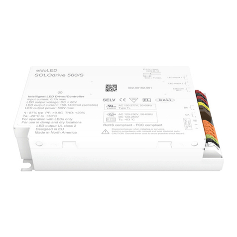
eldoLED SOLOdrive 560/S Quick start guide

eldoLED

eldoLED SOLOdrive 560/S Quick start guide

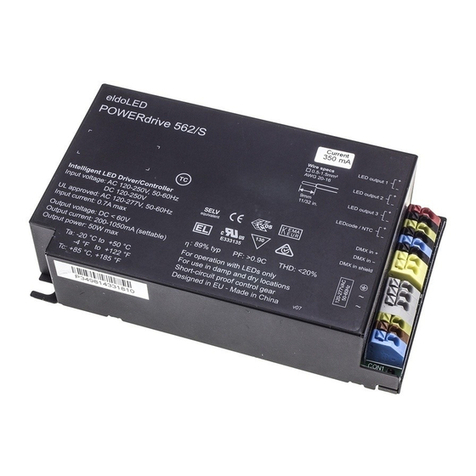
eldoLED POWERdrive 562/S User manual

eldoLED

eldoLED POWERdrive 562/S User manual

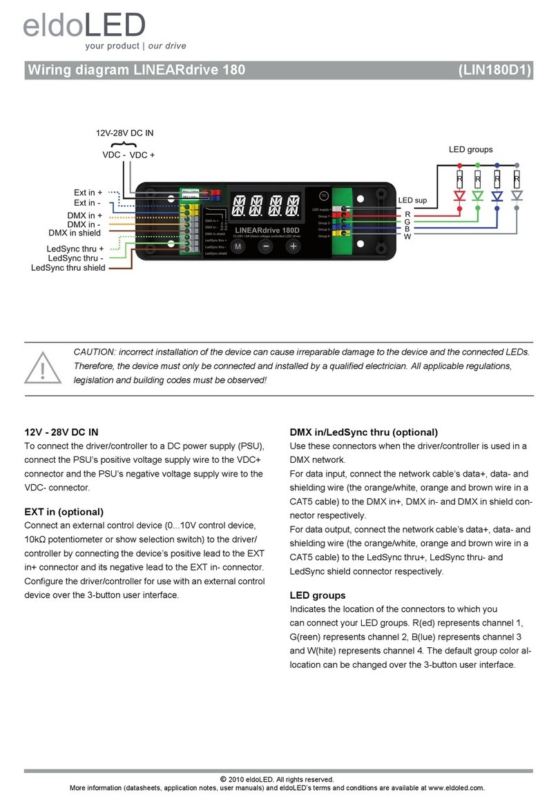
eldoLED LINEARdrive 180 Quick start guide

eldoLED

eldoLED LINEARdrive 180 Quick start guide

eldoLED LINEARdrive 720D User manual

eldoLED

eldoLED LINEARdrive 720D User manual

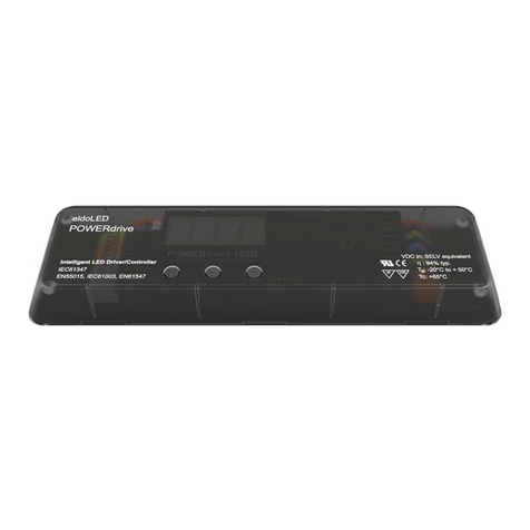
eldoLED POWERdrive 45D Quick start guide

eldoLED

eldoLED POWERdrive 45D Quick start guide

eldoLED ECOdrive Series User manual

eldoLED

eldoLED ECOdrive Series User manual

eldoLED POWERdrive 561/M Quick start guide

eldoLED

eldoLED POWERdrive 561/M Quick start guide

eldoLED LINEARdrive 720D User manual

eldoLED

eldoLED LINEARdrive 720D User manual

eldoLED POWERdrive 106/S Quick start guide

eldoLED

eldoLED POWERdrive 106/S Quick start guide

Popular DC Drive manuals by other brands

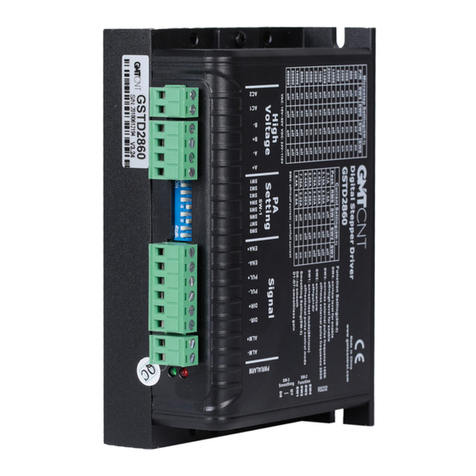
GMTCNT GSTD2860 user guide

GMTCNT

GMTCNT GSTD2860 user guide

Hubner TDP 0,7 Series Assembly instructions

Hubner

Hubner TDP 0,7 Series Assembly instructions

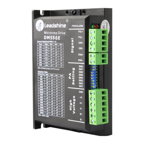
Leadshine DM556E user manual

Leadshine

Leadshine DM556E user manual

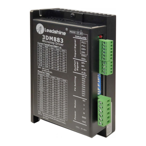
Leadshine 3DM883 user manual

Leadshine

Leadshine 3DM883 user manual

Eurotherm Drives 514C Series Setting up & Commissioning

Eurotherm Drives

Eurotherm Drives 514C Series Setting up & Commissioning

Afag PEZ-52 Maintenance instructions

Afag

Afag PEZ-52 Maintenance instructions

Danfoss VLT HVAC Basic Drive FC 101 Design guide

Danfoss

Danfoss VLT HVAC Basic Drive FC 101 Design guide

Emerson unidrive sp user guide

Emerson

Emerson unidrive sp user guide

Epson S1F76680 Technical manual

Epson

Epson S1F76680 Technical manual

EKSMA OPTICS DQ-100-4 Technical description

EKSMA OPTICS

EKSMA OPTICS DQ-100-4 Technical description

Danfoss ADAP-KOOL AKD 102 operating instructions

Danfoss

Danfoss ADAP-KOOL AKD 102 operating instructions

ABB ACS880-04FXT Hardware manual

ABB

ABB ACS880-04FXT Hardware manual

YASKAWA JOHB-SMP3 Technical manual

YASKAWA

YASKAWA JOHB-SMP3 Technical manual

Griven AL2118 instruction manual

Griven

Griven AL2118 instruction manual

Copley Controls Accelnet manual

Copley Controls

Copley Controls Accelnet manual

Samson 3278 TRANSLATION OF ORIGINAL INSTRUCTIONS

Samson

Samson 3278 TRANSLATION OF ORIGINAL INSTRUCTIONS

gefran ADV200-SI Series user manual

gefran

gefran ADV200-SI Series user manual

ABB ACH580-01 Series Quick installation and start-up guide

ABB

ABB ACH580-01 Series Quick installation and start-up guide

manuals.online logo
manuals.online logoBrands
  • About & Mission
  • Contact us
  • Privacy Policy
  • Terms and Conditions

Copyright 2025 Manuals.Online. All Rights Reserved.