THORLABS MTS25-Z8 User manual

MTS25-Z8 and MTS50-Z8
Brushed DC Motorized
Translation Stages
Original Instructions
HA0210T

Page 0
MTS25-Z8 and MTS50-Z8 DC Motorized Translation Stages
Contents
Chapter 1 Overview ...............................................................................................................1
1.1 Introduction..................................................................................................1
Chapter 2 Safety.....................................................................................................................2
2.1 Safety Information.......................................................................................2
2.2 General Warnings........................................................................................2
Chapter 3 Installation............................................................................................................3
3.1 Environmental Conditions ........................................................................3
3.2 Mounting........................................................................................................4
3.2.1 Invalidation of Warranty..................................................................................4
3.2.2 General.............................................................................................................4
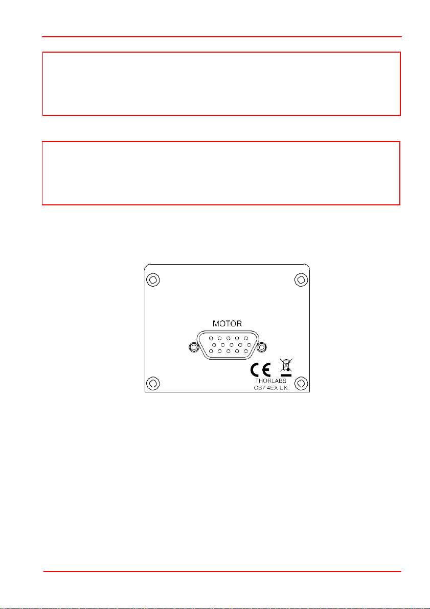
3.2.3 Connecting The Motor Driver.........................................................................5
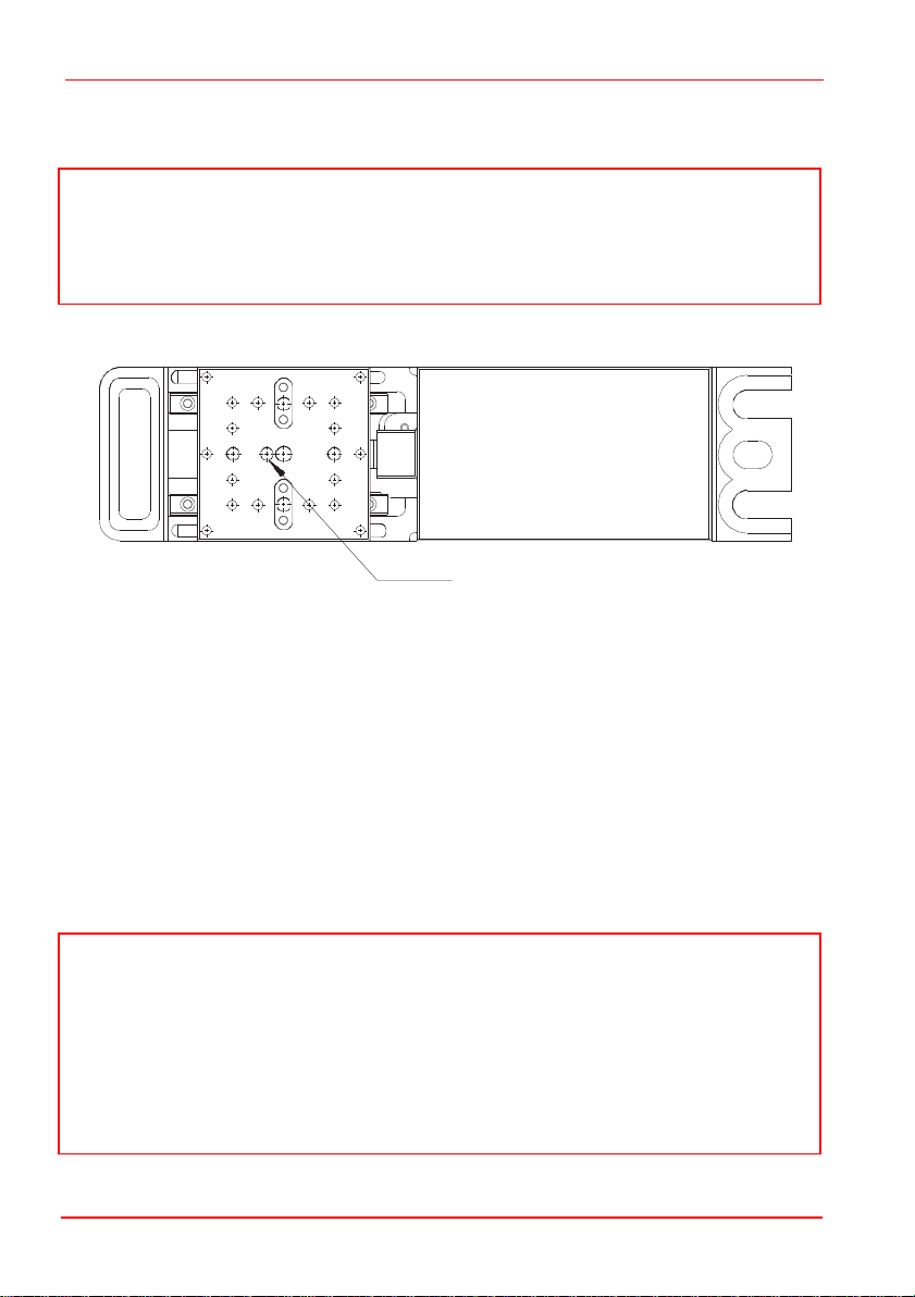
3.2.4 Fitting and Removing the Base Plate............................................................6
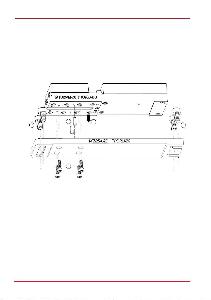
3.2.5 Building an XY Configuration.........................................................................7
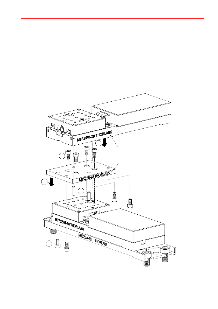
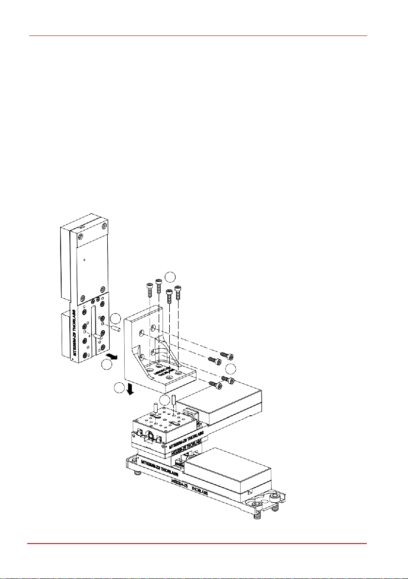
3.2.6 Building an XYZ Configuration.......................................................................8
3.3 Transportation..............................................................................................9
3.4 Dimensions................................................................................................ 10
3.4.1 MTS Dimensions ...........................................................................................10
Chapter 4 Operation........................................................................................................... 11
4.1 General....................................................................................................... 11
Chapter 5 Specifications................................................................................................... 13
5.1 Stage Specifications................................................................................ 13
5.2 Motor Specifications.................................................................................14
Chapter 6 Motor Pin Out Details & Associated Parts................................................. 15
6.1 Motor Connector Pin Out........................................................................ 15
6.2 Associated Products............................................................................... 15
Chapter 7 Regulatory ......................................................................................................... 16
7.1 Declarations Of Conformity....................................................................16
7.1.1 For Customers in Europe .............................................................................16
7.1.2 For Customers In The USA..........................................................................16
7.2 CE Certificates........................................................................................... 17
Chapter 8 Thorlabs Worldwide Contacts ...................................................................... 18
19593-D02

Chapter 1 Overview
Chapter 1 Overview
1.1 Introduction
The compact, motorized MTS Series stages feature a dual set of linear rails with
continuously recirculating ball bearings on a moveable carriage. This mechanism
provides smooth, low friction movement and ensures high load capacity.
The drive power is provided by a brushed DC servo motor. A built-in hall effect
encoder provides 12,288 counts per revolution and a single encoder count
represents 29 nm of motion; the actual minimum repeatable incremental movement
of the stage itself is 0.8 µm.
The addition of limit switches on the stage ensures controlled motion within the
parameters of the unit and prevents overdriving in both directions. Two travel ranges
are available: 25 mm (1") and 50 mm (2"). The stages are configurable in XY, XZ, and
XYZ in both left- and right-handed configurations using spacer plates (MTS25B-Z8
and MTS50B-Z8) and angle brackets (MTS25C-Z8 and MTS50C-Z8) available
separately). Base plates (MTS25A-Z8 and MTS50A-Z8) allow the stages to be bolted
directly to an optical table. For added flexibility, both sizes of travel stages can be
configured together.
For attachment to other stages or fittings, please contact Tech Support.
Fig. 1.1 Typical MTS stage and driver set up
Rev K Jul 2021 Page 1

Page 2
19593-D02
Warning: Risk of Electrical Shock
Given when there is a risk of injury from electrical shock.
Warning
Given when there is a risk of injury to users.
Caution
Given when there is a risk of damage to the product.
Note
Clarification of an instruction or additional information.
Warning
If this equipment is used in a manner not specified by the manufacturer, the
protection provided by the equipment may be impaired. In particular, excessive
moisture may impair operation.
Spillage of fluid, such as sample solutions, should be avoided. If spillage does
occur, clean up immediately using absorbent tissue. Do not allow spilled fluid to
enter the internal mechanism.
Chapter 2 Safety
2.1 Safety Information
For the continuing safety of the operators of this equipment, and the protection of the
equipment itself, the operator should take note of the Warnings, Cautions and Notes
throughout this handbook and, where visible, on the product itself.
The following safety symbols may be used throughout the handbook and on the
equipment itself.
2.2 General Warnings

Page 3
Rev K Jul 2021
Chapter 3 Installation
Note
Retain the packing in which the unit was shipped, for use in future transportation.
Caution
Once removed from its packaging, the stage can be easily damaged by
mishandling. The unit should only be handled by its base, not by any
attachments to the moving platform.
Warning
Operation outside the following environmental limits may adversely affect
operator safety.
Chapter 3 Installation
3.1 Environmental Conditions
Location: Indoor use only
Maximum altitude: 2000 m
Temperature range: 5oC to 40oC
Maximum Humidity: Less than 80% RH (non-condensing) at 31°C
To ensure reliable operation the unit should not be exposed to corrosive agents or
excessive moisture, heat or dust.
If the unit has been stored at a low temperature orin anenvironment of high humidity,
it must be allowed to reach ambient conditions before being powered up.
The unit must not be used in an explosive environment.

MTS25-Z8 and MTS50-Z8 DC Motorized Translation Stages
Page 4
19593-D02
Caution
The moving platform features a locking screw for the anti-
backlash nut inside
thestage. This locking screw, highlighted in Fig 3.1
, is set during assembly at
the
factory and must not be removed or adjusted. Tampering with this screw
will invalidate the warranty.
Caution
The stages are set up and calibrated at the factory and no further adjustment is
necessary.
Do not allow screws or other objects to protrude through the top platform as this
could damage the internal mechanism.
When mounting components, or fitting the stage within an application, do not
apply excessive pressure to the moving platform as this may damage the
bearing mechanism.
3.2
Mounting
3.2.1 Invalidation of Warranty
Locking Screw for
Anti-backlash Nut
DO NOT TAMPER
Fig. 3.1 Anti-backlash Nut Locking Screw
3.2.2
General
The MTS series stages can be mounted horizontally or vertically using the base
plates, spacer plates and angle brackets previously mentioned - see Section 1.1.
When mounting the stage close to other equipment, ensure that the travel of the
moving platform is not obstructed. If equipment mounted on the moving platform is
driven against a solid object, damage to the internal mechanism could occur.
The range of travel is: MTS25 stages: 25 mm, MTS50 stages: 50 mm

Chapter 3 Installation
Page 5
Rev K Jul 2021
Caution
It is recommended that the MTS series stages be driven by the Thorlabs
KDC101 DC Servo Motor Driver. If the stage is being driven by any other driver
or controller, consult Section 6.1. for motor pin out details and Chapter 5 for
details of the motor specification.
3.2.3 Connecting The Motor Driver
The stage is supplied with 0.5m (1.6 ft) of cable and is terminated in a 15 pin D-Type
connector. This is compatible with the MOTOR drive terminal of the KDC101 K-
Cube DC driver unit - see Fig. 3.2 below. A 2.5 m (8.2 ft) extension cable (PAA632)
is available on request
Fig. 3.2 KDC101 rear panel
Note
The MTS series stages can quickly be assembled into XY, XZ, YZ and XYZ
configurations - see Section 3.2.4. and Section 3.2.5. The brackets and plates are
supplied complete with dowels, which ensure an accurate, orthogonal assembly,
and all bolts.

MTS25-Z8 and MTS50-Z8 DC Motorized Translation Stages
Page 6
19593-D02
1
4
2
4
3.2.4 Fitting and Removing the Base Plate
Referring to Fig. 3.3, proceed as follows:
1) Fit the dowels supplied to the base plate (MTS25A-Z8 or MTS50A-Z8).
2) Position the stage on the base plate, ensuring that the dowels locate correctly in
the holes in the lower surface of the stage.
3) Fit the four boltssuppliedM3x 10 (4-40 x1/2”) through the holes in theunderside
of the base plate, and tighten to secure the stage in place.
Fig. 3.3 Fitting the MTS25A-Z8 Base Plate
4) Fit two of the bolts supplied M6 x 10 (1/4-20 x 3/8”) through each end of the base
plate to fix the stage to the work surface.
5) To remove the base plate, reverse the procedure above.
3

Chapter 3 Installation
Page 7
Rev K Jul 2021
4
3
Note orientation of plate
and
upper stage
(part numbers aligned)
2
1
5
3.2.5 Building an XY Configuration
Referring to Fig. 3.4, proceed as follows:
1) Fit the dowels supplied to the moving platform of the lower stage.
2) Note the orientation of the spacer plate in the drawing below, then fit the spacer
plate (MTS25B-Z8 or MTS50B-Z8) to the moving platform of the lower stage,
ensuring that the dowels locate correctly in the holes and protrude through the top
surface of the spacer plate.
3) Fit the four bolts supplied M3 x 6 (4-40 x 1/4”), through the holes in the spacer
plate, and tighten to secure the plate in place.
4) Fit the Y-axis stage into place ensuring that the dowels in the spacer plate locate
correctly in the holes in the lower surface of the stage.
Fig. 3.4 Building an XY Configuration

MTS25-Z8 and MTS50-Z8 DC Motorized Translation Stages
Page 8
19593-D02
3
4
5
6
2
1
5) Fit the four bolts supplied M3 x 6 (4-40 x 1/4”) through the holes in the underside
of the spacer plate and screw into the base of the upper stage.
6) Tighten the bolts to secure the stage in place.
7) Fit the base plate to the X-axis (lower) stage, and bolt the assembly to the
worksurface as detailed in Section 3.2.4.
3.2.6 Building an XYZ Configuration
Assemble an XY configuration as detailed in Section 3.2.5. then, referring to Fig. 3.5,
proceed as follows:
1) Fit the shorter dowels supplied, into the moving platform on the upper stage of the
XY assembly.
2) Fit the angle bracket (MTS25C-Z8 or MTS50C-Z8) onto the moving platform of the
stage, ensuring that the dowels fitted at item (1) locate correctly in the holes on
the underside of the angle bracket.
Fig. 3.5 Adding a Vertical Axis Stage

Chapter 3 Installation
Page 9
Rev K Jul 2021
3) Fit the four bolts supplied M3 x 12 (4-40 x 1/2”), through the holes in the base of
the angle bracket, and tighten to secure the bracket to the XY assembly.
4) Fit the longer dowels supplied to the underside of the base on the vertical-axis
stage.
5) Fit the vertical-axis stage into place ensuring that the dowels fitted at item (4)
locate correctly into the holes in the back surface of the angle bracket.
6) Fit the four bolts supplied M3 x 12 (4-40 x 1/2”), through the holes in the angle
bracket, and screw into the base of the vertical-axis stage.
7) Tighten the bolts to secure the stage in place.
8) Fit the base plate to the X-axis (lower) stage, and bolt the assembly to the
worksurface as detailed in Section 3.2.4.
3.3 Transportation
Fig. 3.6 Typical XYZ configuration
Caution
When packing the unit for shipping, use the original packing. If this is not
available, use a strong box and surround the unit with at least 100 mm of shock
absorbent material.

Page 10
19593-D02
1.14
(29.0)
Length B
Length A
Caution
The stages are set up and calibrated at the factory and no further adjustment is
necessary. Do not allow screws or other objects to protrude through the top
platform as this could damage the internal mechanism.
3.4
Dimensions
3.4.1 MTS Dimensions
All dimensions are given in the format: inches (mm)
8-32 (M4)
mounting hole
4-40 (M3)
mounting holes
(14 places)
4-40 (M3) mounting holes
(4 places)
MTS25X MTS50X
LengthA 5.31 (134.8) 6.33 (161.0)
Length B 6.69 (170.0) 7.68 (195.0)
1.70 1.5 1.0 0.5
(43.0) (37.5) (25.0) (12.5)
Locking Screw for
Anti-backlash Nut
DO NOT TAMPER
0.5
(12.5)
1.0
(25.0)
1.5
(37.5)
1.70
(43.0)
2 holes for alignment pins
25mm spacing
Fig. 3.7 Dimensions

Chapter 4 Operation
Page 11
Rev K Jul 2021
Caution
The MTS series stages form part of the Thorlabs Nanopositioning system. We
recommend they are driven by the Thorlabs KDC101 K-Cube Brushed
DC
Servo Motor
Driver. If the stage is being driven by any other driver or
controller, consult
Section 6.1. for motor pin out details and Chapter 5 for
details of the motor specification.
The stages are set up and calibrated at the factory and no further adjustment is
necessary. Do not allow screws or other objects to protrude through the top
platform as this could damage the internal mechanism.
Note
The USB cable should be no more than 3 meters in length. Communication lengths
in excess of 3 meters can be achieved by using a powered USB hub.
Chapter 4 Operation
4.1
General
The stages are connected to the controller via a flying lead terminated in a D-type
connector.
For a complete tutorial on using the stage with a motor controller, see the relevant
controller manual. Basic steps in controlling the stage are as follows:
1) Perform the mechanical installation as detailed in Section 3.2.
2) Connect the stage to the DC motor driver - see Section 3.2.3.
3) Connect the driver to the main supply and switch ‘ON’.
4) Connect the driver unit to your PC.
5) When using the stages in conjunction with the recommended Thorlabs KDC101
controllers, two software options are available: Kinesis®and APT™. The initial
start up routine is essentially the same in both cases, using the respective GUIs
shown in Figure 4.1 and 4.2. These are activated by running:
Start/Programs/Thorlabs/APT User/APT User for the APT GUI
Start/Programs/Thorlabs/Kinesis/Kinesis for the Kinesis GUI
6) Check that the correct stage/actuator has been read, as displayed on the GUI
(bottom right for Kinesis; bottom left for APT). If it hasn’t, the stage may not
operate correctly, and a manual intervention will be required (for details, refer to
the relevant KDC101 controller handbook).
Warning
The controller must be switched OFF before the stages are plugged in or
unplugged. Failure to switch the controller off may result in damage to either the
controller, the stage, or both.

Page 12
19593-D02
Caution
During item (7) the stage should be homed using the button on the GUI panel.
Do not jog the stage to the zero-position using the jog buttons as this could
establish a false zero datum; there is also a risk that the stage could
overshoot its end stops and become stuck.
Fig. 4.1 APTUser GUI screen
Fig. 4.2 Kinesis GUI screen
7) Move the stage to its home position by pressing “Home” on the GUI, to establish
the zero-datum point. Pay special attention to the Caution note below with
regards to not using the jog buttons for this operation.
The stage is now ready for use and/or implementation of parameter changes, as
detailed in the relevant Kinesis/APT manual for the KDC101 controller.

Chapter 5 Specifications
Page 13
Rev K Jul 2021
Chapter 5 Specifications
5.1 Stage Specifications
Parameter Value
Stage
MTS25(/M)
MTS50(/M)
Travel Range
25 mm (1”)
50 mm (2”)
Bidirectional Repeatability
±0.8 µm
Backlash
<6 µm
Maximum Acceleration
4.5 mm/s2
Maximum Velocity
2.4 mm/s
Max Vertical On-Axis Load Capacity
4.5 kg (10 lbs)
Max Horizontal On-Axis Load Capacity
12 kg (25 lbs)
MinTheoretical Incremental Movement a
0.03 µm
Min Repeatable Incremental Movement
0.8 µm
Absolute On-axis Accuracy
145 µm
290 µm
Maximum Percentage Accuracy
0.3%
0.7%
Home Location Accuracy
± 4.0 µm
Pitch
±0.02°
±0.025°
Yaw
±0.025°
±0.03°
Weight
0.31 kg
0.34 kg
Software Compatibility
APT: Server CDM621 V2.9.0 or later.
Kinesis: V1.14.28 or later.
a. This represents 1 encoder count.

Page 14
19593-D02
5.2 Motor Specifications
Parameter Value
Motor Type
Brushed DC Servo
Motor Drive Voltage
6 V
No load speed
6560 rpm
No load current
7.43 mA
Nominal speed
1050 rpm
Nominal torque (max. continuous torque)
1.26 mNm
Nominal current (max. continuous current)
0.156 A
Stall torque
1.54 mNm
Starting current
0.184 A
Max. efficiency
65%
Terminal resistance
32.7 Ω
Terminal inductance
0.607 mH
Torque constant
8.38 mNm/A
Speed constant
1140 rpm/V
Speed / torque gradient
4450 rpm/mNm
Mechanical time constant
13.9 ms
Rotor inertia
0.298 gcm
2
Recommended Thorlabs controller
KDC101
How to Calculate the Linear Displacement per Encoder Count
For the Z8 series motors, there are 512 encoder counts per revolution of the motor.
The output shaft of the motor goes into a 67.49:1 planetary gear head. This requires the
motor to rotate 67.49 times to rotate the 1.0 mm pitch lead screw once (i.e. advance the
position by 1.0 mm).
To calculate the linear displacement of the actuator per encoder count:
512 x 67.49 = 34,555 encoder counts per revolution of the lead screw
Linear displacement of the lead screw per encoder count is:
1.0 mm / 34,555 counts = 2.9 x 10⁻⁵ mm (29 nm)

Chapter 6 Motor Pin Out Details & Associated Parts
Rev K Jul 2021
Page 15
1
6
11
5
10
15
Chapter 6 Motor Pin Out Details & Associated Parts
6.1 Motor Connector Pin Out
The Motor cable is terminated in a 15 way D-type connector, which provides
connection to the DC motor controller. The pin functions are detailed in Fig. 6.1.
Pin
Description
Pin
Description
1
Ground/Return
9
Ident
2
Forward Limit Switch
10
Vcc
3
Reverse Limit Switch
11
Encoder A
4
12
5
Motor -
13
Encoder B
6
14
7
Motor +
15
8
Fig. 6.1 Motor Connector Pin Descriptions
6.2 Associated Products
Product Name Part Number
Base Plate for MTS25-Z8 Stages
MTS25A-Z8
Base Plate for MTS50-Z8 Stages
MTS50A-Z8
XYAdapter Plate for MTS25-Z8 Stages
MTS25B-Z8
XYAdapter Plate for MTS50-Z8 Stages
MTS50B-Z8
Right Angle Bracket for MTS25-Z8 Stages
MTS25C-Z8
Right Angle Bracket for MTS50-Z8 Stages
MTS50C-Z8
MTS25-Z8 60mm cage system adapters
MTS25CSA
MTS50-Z8 60mm cage system adapters
MTS50CSA
Note. All the above parts fit both imperial and metric products.

MTS25-Z8 and MTS50-Z8 DC Motorized Translation Stages
Page 16
19593-D02
Chapter 7 Regulatory
7.1 Declarations Of Conformity
7.1.1 For Customers in Europe
See Section 7.2.
7.1.2 For Customers In The USA
This equipment has been tested and found to comply with the limits for a Class A
digital device, pursuant to part 15 of the FCC rules. These limits are designed to
provide reasonable protection against harmful interference when the equipment is
operated in a commercial environment. This equipment generates, uses and can
radiate radio frequency energy and, if not installed and used in accordance with the
instruction manual, may cause harmful interference to radio communications.
Operation of this equipment in a residential area is likely to cause harmful interference
in which case the user will be required to correct the interference at his own expense.
Changes or modifications not expressly approved by the company could void the
user’s authority to operate the equipment.

Chapter 7 Regulatory
Rev K Jul 2021
Page 17
7.2 CE Certificates

MTS25-Z8 and MTS50-Z8 DC Motorized Translation Stages
Page 18
19593-D02
Chapter 8 Thorlabs Worldwide Contacts
For technical support or sales inquiries, please visit www.thorlabs.com/contact for
our most up-to-date contact information.
Thorlabs verifies our compliance with the WEEE (Waste Electrical and
Electronic Equipment) directive of the European Community and the
corresponding national laws. Accordingly, all end users in the EC may return
“end of life” Annex I category electrical and electronic equipment sold after
August 13, 2005 to Thorlabs, without incurring disposal charges. Eligible units
are marked with the crossed out “wheelie bin” logo (see right), were sold to
and are currently owned by a company or institute within the EC, and are not
dissembled or contaminated. Contact Thorlabs for more information. Waste
treatment is your own responsibility. “End of life” units must be returned to
Thorlabs or handed to a company specializing in waste recovery. Do not
dispose of the unit in a litter bin or at a public waste disposal site.
USA, Canada, and South America
Thorlabs, Inc.
sales@thorlabs.com
techsupport@thorlabs.com
UK and Ireland
Thorlabs Ltd.
sales.uk@thorlabs.com
techsupport.uk@thorlabs.com
Europe
Thorlabs GmbH
europe@thorlabs.com
Scandinavia
Thorlabs Sweden AB
scandinavia@thorlabs.com
France
Thorlabs SAS
sales.fr@thorlabs.com
Brazil
Thorlabs Vendas de Fotônicos Ltda.
brasil@thorlabs.com
Japan
Thorlabs Japan, Inc.
sales@thorlabs.jp
China
Thorlabs China
chinasales@thorlabs.com
This manual suits for next models
1
Table of contents
Other THORLABS DC Drive manuals
Popular DC Drive manuals by other brands

Parker
Parker DC590PR Series quick start

ABB
ABB ACH580 Series How to set up

YASKAWA
YASKAWA SI-EN3 installation manual

Lenze
Lenze L-force EYF Series Mounting instructions

ADADVANCED Motion Controls
ADADVANCED Motion Controls DigiFlex Performance Hardware installation manual

Invertek Drives
Invertek Drives Optidrive E2 Application note

Danfoss
Danfoss VLT Flow Drive FC 111 Design guide

Shihlin
Shihlin SS2 Series installation guide

Emerson
Emerson E Series installation manual

Leadshine Technology
Leadshine Technology DM503 Specification and user manual

Siemens
Siemens SINAMICS S120 manual

Lenze
Lenze E84AVHCE HighLine C Series Mounting instructions