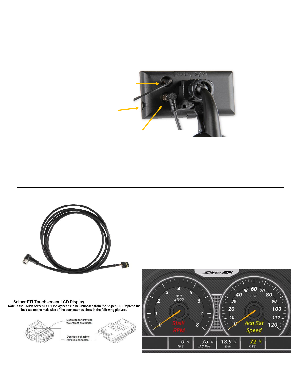
Holley Sniper EFI User manual

1
5” Sniper EFI Digital Dash
553-200
User Manual

2
Contents
MOUNTING.......................................................................................................................................................3
CONNECTIONS................................................................................................................................................4
CAN/POWER.................................................................................................................................................4
MAKING ADJUSTMENTS.................................................................................................................................5
HOME SCREEN................................................................................................................................................5
TUNING.............................................................................................................................................................6
MONITOR .......................................................................................................................................................14
SETTINGS.......................................................................................................................................................17
WIZARD..........................................................................................................................................................21

3
MOUNTING
The 5” Sniper Dash comes with a suction cup mount and two different length mounting stands, offering a wide
variety of mounting solutions. The mounting stands slide into the back of the display, as shown below.
PACKAGE CONTENTS
Modular Mounting Brackets
Slide mount into display housing.
To release from housing, press the locking clip and slide.
Suction cup mount will then slide into the grooves on the bracket.

4
CONNECTIONS
CAN/POWER
Connect the harness from the CAN connector on the
vehicle’s main harness to the 5” Sniper Dash.
A 4 pin male receptacle connector is used to connect to the
Sniper EFI Main Harness.
Once all connections have been made, the Sniper EFI 5”
Dash may be powered up. After a brief initial loading
sequence, the default gauge display will appear.
GPS Antenna Connection
PUSH ON & PULL OFF Connection
DOES NOT REQUIRE TURNING
Handheld CAN Connection
CAN Cable features indexing key and attaches
to the Display via threaded collar. Other end of
cable connects directly to the Sniper EFI
Throttle Body
Micro SD
Card Slot

5
MAKING ADJUSTMENTS
Slider Bar: Slide the bar left or right with the stylus, or use the right and left arrow keys for fine adjustment.
List: Use the scroll bar on the right hand side of the screen to view all list entries. Touch the desired list item
and click ‘OK’ to make a selection.
HOME SCREEN
The home screen contains icons which will navigate to different functional features of the 5” Dash. These
features will be discussed in detail throughout this manual. After 7 seconds, the left menu will slide off the side
of the display. It can be accessed again by tapping the screen and pressing the Menu Icon.
Home Screen

6
TUNING
The Sniper 5” Dash facilitates ‘laptop-free’ tuning changes to help optimize mileage, drivability, and
performance. Tuning is categorized by “Basic”, “System”, “Advanced”, “Advanced 2” and “Super Sniper”.
BASIC TUNING
From the Left MENU, select TUNING, then BASIC. There are four areas you can modify, BASIC FUEL,
CLOSED LOOP & LEARN, BASIC IDLE, and SPARK. These are reviewed below.
BASIC FUEL
Selecting BASIC FUEL brings up the following menu:

7
TARGET AFR:
Allows changes to the Target Air/Fuel ratio at idle, cruise, and wide open throttle. The following are typical
values and some tuning notes.
Idle Air/Fuel Ratio –Typically between 15” and 15.0. Engines with larger cams may need a
richer setting for smoothest idle.
Cruise Air/Fuel Ratio –Typically between 15” and 15.5. Engines with larger cams may need a
richer setting for smoothest operation.
Wide Open Throttle Air/Fuel Ratio (WOT) –Typically between 12.0 and 13.0. Running richer
may reduce power. Running leaner may reduce power or cause potential engine damage.
AFR Boost Offset –Modifies the target AFR while under boost. The input is how much you would
like the Air/Fuel Ratio decreased per 7 PSI of boost. This will richen up the Air/Fuel Ratio. Good
starting point would be 0.3-0.4 AFR offset per 7 PSI of Boost. There are 4 boxes that will show up
when modifying this parameter. Each box corresponds to the target AFR at 0 PSI, 7PSI, 14PSI & 21PSI
of boost.
NOTE: The Target Air/Fuel setting between IDLE, CRUISE, and WOT is blended together automatically.
Consequently, the air/fuel you see on the MONITOR screen, may not be exactly what you set for the
settings. Changing these settings raises or lowers the “curve” of that specific area.

8
ACCELERATION ENRICHMENT:
This changes the “accelerator pump” function of the fuel injection. Raising the number increases the amount of
fuel added when the pedal is pushed. Lowering the number decreases the amount of fuel added when the
pedal is pushed. It is highly recommended NOT to change this until the ECU is allowed to perform self-tuning.
FUEL PRIME:
Fuel prime is an option that is enabled by default in all
of the base calibrations. The fuel prime function injects
a small shot of fuel into the intake manifold when the
ignition is turned on, wetting the intake and allowing the
engine to start much quicker. The amount of fuel is
based on the engine temperature and how long it was
since the engine previously ran. This amount of fuel
can be increased or decreased by changing the
“Percent” value. If the engine seems flooded, reduce
this value. If the engine seems to want more fuel,
increase it. Experiment for best results.
NOTE: This only injects fuel once at key-on, and will not do it again until the engine has run. This fuel prime
occurs ½ of a second after key-on. If you quickly turn the ignition key without waiting for ½ a second,
the prime will not occur and it may take longer for the engine to start.

9
CLOSED LOOP & LEARN
CLOSE LOOP ENABLE / DISABLE:
The Closed Loop Enable / Disable menu turns Closed Loop “On” and “Off”. If enabled, the fuel table will be
modified based on target AFR vs Actual Wideband AFR.
LEARN ENABLE / DISABLE:
The LEARN Enable / Disable menu turns the Self Tuning “On” and “Off”. If enabled, self-tuning is performed.
Learning should be enabled when an engine is just started and the tuning process is occurring. After the
vehicle is driven under various operating conditions, and is running well, it is advised to disable learning, OR
slow the Learn Speed to “Slow”.

10
BASIC IDLE
Selecting BASIC IDLE allows you to change the Target Engine Idle Speed. This should be adjusted to your
desired idle RPM. Values between 650-800 rpm are typical. Larger camshafts or aftermarket torque
converters may require a slightly higher value to maintain proper idle quality while in gear.
All Sniper base tunes contain timing curves that will provide adequate engine operation, however the ignition
timing at idle, cruise, and wide open throttle can be adjusted independently from each other to compensate for
geographical and climate extremes.
The following are typical values for each:
•Idle Timing –18-34 degrees is typically used at idle. The larger the camshaft, the more timing is
usually used.
•Cruise Timing –32-48 degrees is typically used when cruising for optimal fuel economy.
•Wide Open Throttle Timing (WOT) –WOT timing is typically between 26-38 degrees.
•Boost Timing Retard –Retards the timing from the WOT timing setting per pound of boost. Good
starting point is 1 degree of timing retard per lb. of boost. There are 4 boxes that will show up when
modifying this parameter. Each box corresponds to the total timing at 0 PSI, 7PSI, 14PSI & 21PSI of
boost.
NOTE: Too much timing can cause pre-ignition that can damage an engine. Be cautious when tuning.
NOTE: The actual timing between IDLE, CRUISE, and WOT is blended together automatically.
Consequently, the timing you see on the MONITOR screen, may not be exactly what you set for these
settings. Changing these settings raises or lowers the “curve” of that specific area.

11
SYSTEM TUNING
From the HOME MENU, select TUNING, and SYSTEM. There are four areas you can modify: OUTPUTS,
ENGINE SETUP, SNIPER SETUP, IGNITION SETUP, and STATIC TIMING.
OUTPUTS
The OUTPUT screen allows for the Fan #1 and Fan #2 ON and OFF temperatures to be adjusted. The ON
temp needs to always be a higher value than the OFF temp. Use a difference of at least 5 degrees so they
aren’t cycling excessively. In Sniper Kits these are ground outputs that should be wired to trigger the fan
relays. NEVER wire them directly to the fans! The AC Disable value is a TPS value above which a 12 volt
output is sent out to deactivate the air conditioning compressor at wide open throttle.
Detailed wiring instructions are provided with Sniper EFI Kits.

12
ENGINE SETUP
Number of Cylinders: Select how many cylinders your engine has, 4, 6, or 8.
Engine Displacement: Enter how many cubic inches your engine is.
CAM Type: Select your Camshaft Type: Stock -This selection will work well on most applications equipped
with stock or “street performance” camshafts. Choose Stock or Mild If you are unsure of your camshaft specs.
Street/Strip - Select this if your engine has between 8” and 13” of manifold vacuum *Race - Select this if your
engine has less than 7” of manifold vacuum. Race oriented camshafts may require laptop tuning for optimal
idle stability. Selecting Race will disable Closed Loop Control at Idle. Make this selection if your engine
has open headers.

13
IGNITION SETUP
Ignition Type: Select how the Sniper ECU will be receiving the RPM signal from your engine. Coil (-) [no
timing control] CD Ignition Box [no timing control] Magnetic Distributor Holley Dual Sync Distributor
HyperSpark Distributor
Reference Angle (Timing Control Only): This is the value in crank degrees of the distributor's crank pulse.
These values are preset in the base calibrations and should not need to be adjusted
Main Rev Limiter: The RPM threshold where the Injectors will turn off.
Inductive Delay (Timing Control Only): Use this value to sync timing at higher RPMs. These values are
preset in the base calibrations. Some ignition modules may need this number altered if the commanded timing
does not match the commanded timing as engine speed increases. If the timing starts to retard as rpm
increases, this number can be increased in order for the timing to match. Recommended increments is in 20
usec until the timing matches the commanded at all RPMs.

14
MONITOR
Choose MONITOR from the HOME screen to access live telemetry and customizable gauge screen options.
The Sniper 5” Dash come pre-loaded with 3 default layouts.
Default Layout 1

15
Default Layout 2
Default Layout 3

16
CHANNELS SCALING
Each channel displayed by the 5” Touchscreen can be configured to have caution and warning
indicators. To do this, choose ‘Ranges’ from the Gauge Settings menu. Cautions will display as
Yellow and Warnings or Alarms will display as RED. Press and hold any gauge on the display to
open the gauge editing menu. This meu will allow you to enable, or disable any gauge channel.
Additionally, you can Edit any gauge from this menu, as seen below.

17
SETTINGS
Choose Settings from the HOME screen to access ECU and 5” touchscreen information. This is also
where ECU logging and Global Folder transfer menus are located.
ECU OVERVIEW:
Information specific to the engine and ECU configuration
is shown here, these include the name of the current
global folder, transmission type, ignition input type, WBO2
type, throttle body type, fuel system type, and ECU
firmware version. Note that this menu is view only –no
information can be changed. Any changes to engine or
transmission setup must be done through the TUNING or
WIZARDS menu.
ECU GLOBALS:
This menu will list any global folders that have been
saved to the SD card. It will also allow you to download a
global folder from the ECU to the SD card so that it may
be opened on any Windows based PC with free Sniper
EFI software installed. Software may be downloaded at:
https://www.holley.com/support/fuel_injection/sniper_efi/

18
ECU DATA LOGGING:
Sniper systems come standard with powerful data logging
capabilities. Logging can be stopped and started via the 5”
Handheld, with the SD card inserted, press Start to being
the data log. To stop the log, Press the Stop button, or
cycle the ignition power.
The Sniper 5” Dash Data Logger will also allow you
to set a log trigger, based on a variety of channels,
such as Engine RPM, TPS, or MAP. This method of
triggering a datalog can be using when trying to
capture data under a certain of condition, such as
boost pressure above 4psi, or RPM above 5500.
ECU UPDATE:
Use this menu to update ECU Firmware. Choose the .eep file you are updating the Sniper EFI ECU to. If
there are more than 1 versions of firmware on the SD Card all versions will show up and you will need to
choose the correct version.

19
LOCAL SETUP:
Contains Local Info, Local Options, and Backlight adjustments.
LOCAL INFO
Displays device information and current Firmware Version.
LOCAL OPTIONS
This menu allows you to adjust the display for your local Time and Time zone, Speedometer Units, and Temperature Units.

20
BACKLIGHT:
Can adjust a Night Brightness & Day Brightness defaults, which is toggled by pressing the Sniper EFI logo on
any of the Monitor Screens or within the Backlight Settings menu.
Other manuals for Sniper EFI
1
This manual suits for next models
1
Table of contents
Other Holley Automobile Accessories manuals

Holley
Holley 526-24 User manual

Holley
Holley Sniper EFI 550-849 User manual

Holley
Holley Terminator Stealth EFI User manual

Holley
Holley HOOKER 2253HKR User manual

Holley
Holley Quadrajet Sniper EFI User manual

Holley
Holley EFI 553-133 User manual

Holley
Holley 0-80508S Guide

Holley
Holley NOS 02121NOS User manual

Holley
Holley 550-407 User manual

Holley
Holley FLOWTECH 11133FLT User manual