Holley EFI 553-106 User manual

Digital Dash Quick Start Guide
553-106

2
CONTENTS:
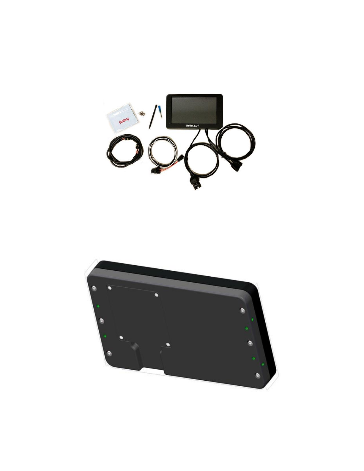
Package Contents.............................................................................................................................................3
Mounting ...........................................................................................................................................................3
Wiring................................................................................................................................................................3
Connectors........................................................................................................................................................4
CAN1/Power...............................................................................................................................................4
USB............................................................................................................................................................4
CAN Adapter Harness................................................................................................................................4
CAN Extension Harness.............................................................................................................................4
Cleaning............................................................................................................................................................5
Touchscreen Basics..........................................................................................................................................5
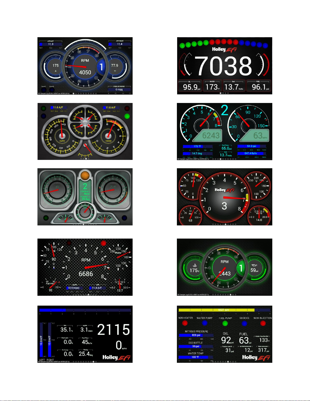
Main Menu.........................................................................................................................................................5
Modifying Channels on a Preconfigured Layout..........................................................................................7
Saving Gauge Screens..................................................................................................................................7
Quick Save.................................................................................................................................................7
Rename and Save......................................................................................................................................7
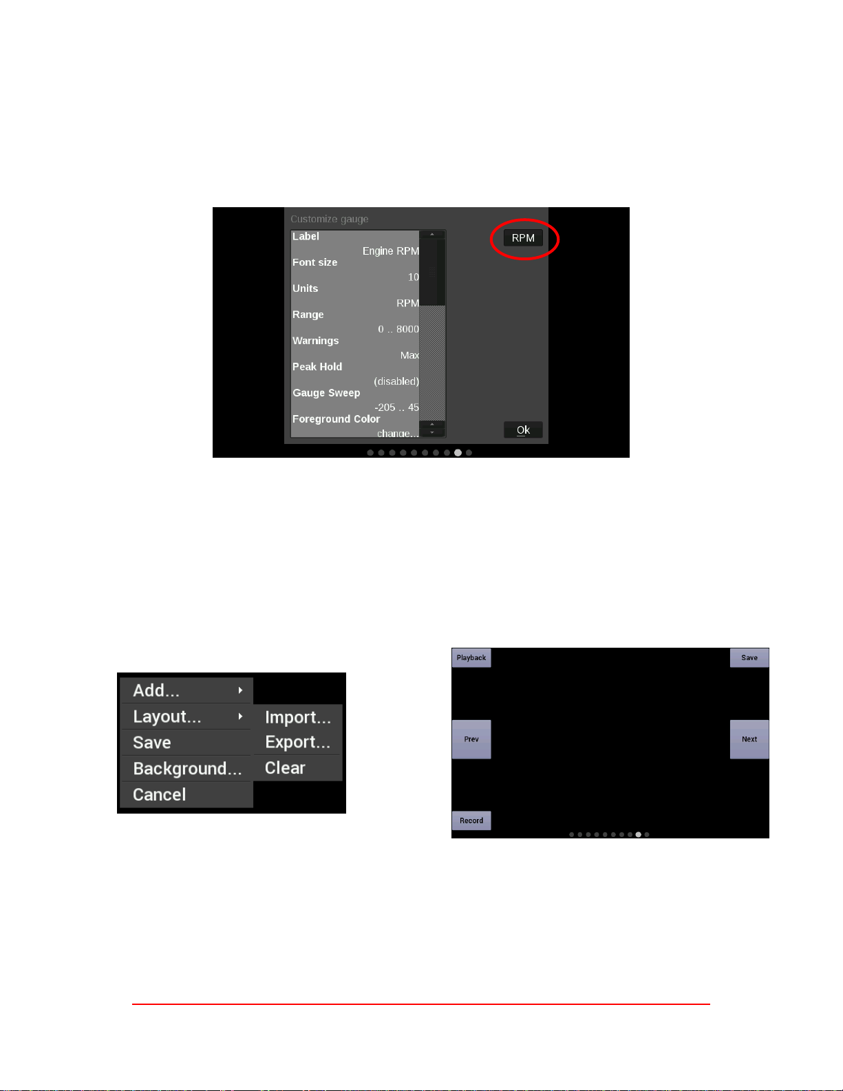
Building a Custom Gauge Screen..................................................................................................................8
Add Gauges ...............................................................................................................................................8
Customizing the Gauge..............................................................................................................................8
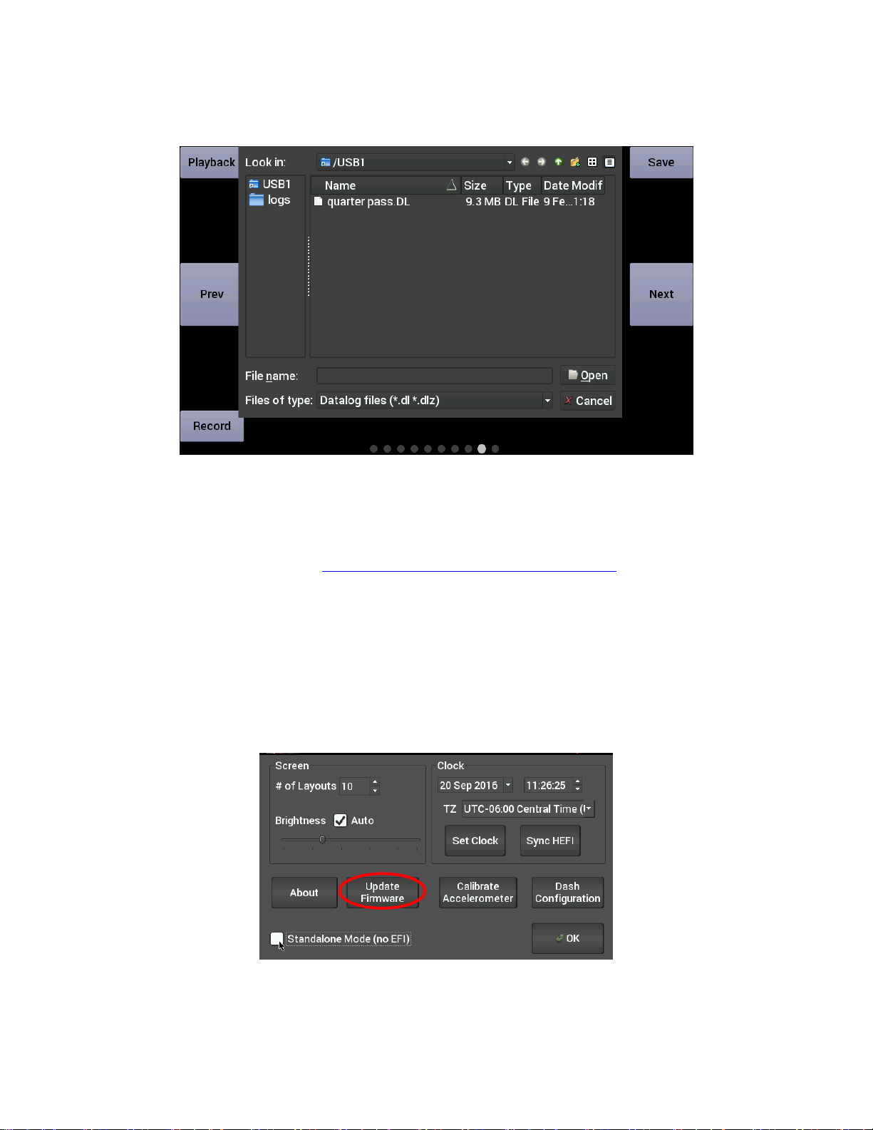
Data Log Playback ............................................................................................................................................9
Firmware Upgrade.............................................................................................................................................9
ATTENTION!
THE CD INCLUDED WITH YOUR DIGITAL DASH CONTAINS A DETAILED USER MANUAL. ONE MAY ALSO BE
FOUND ONLINE AT www.holley.com.

3
Introduction
The Holley EFI Digital Dash is complete customizable with a variety of gauge and indicator screens that can be
programmed to display any parameter you need. This quick start guide will get you up and running with your
new dash. A detailed User Manual can be found on the CD included with your product.
Package Contents
Mounting
The product has eight tapped 8-32 mounting holes to allow the user to surface mount or flush mount the
enclosure. There are four mounting holes located on the rear of the unit, and two mounting holes are located
on the left and right sides. Included with the contents of this kit is a separate template with a 1:1 layout of hole
locations for fabricating a mounting bracket.
Wiring
A CAN/power harness is supplied with the digital dash. Connect the black wire to negative –white wire to a
switched +12V circuit.

4
Connect the harness from the CAN connector on the vehicles main harness to the digital dash using the
supplied 4’ CAN/Power extension
Once all connections have been made, the Holley EFI Digital Dash may be powered up. After a brief initial
loading sequence the gauge display will appear.
Connectors
CAN1/Power
4 pin Mizu-P25 male receptacle connector used to connect main power and to a Holley EFI. The dual
connector allows the product to be connected to multiple devices on the CAN bus.
Pin
Function
Color
Description
1
+12V
WHT
Main power in
2
CAN1H
ORG/BLK
CAN_H Holley EFI communications
3
CAN1L
ORG
CAN_L Holley EFI communications
4
GND
BLK
GND
USB
The unit has two standard USB type A receptacles that can accept USB flash drives for saving data logs,
uploading gauge screen layouts, background images, or firmware updates. You may also use these to
connect to a USB mouse or keyboard.
CAN Adapter Harness
271R1075A CAN ADAPTER HARNESS - used to connect switched +12V ignition power (white wire)
and ground (black wire) to the dash, as well as for connecting to the main harness CAN connector.
CAN Extension Harness
The dash is supplied with a 4’ CAN extension harness. Holley also offers the following replacement harnesses:

5
558-424 –4 feet
558-425–8 feet
558-426 –12 feet
558-428 –9 inches
Cleaning
If screen needs cleaning, use the supplied microfiber cleaning cloth. Do not use harsh chemical cleaners on
the touch screen display.
Touchscreen Basics
The Holley EFI Digital Dash has been designed with a resistive touchscreen, meaning it will work with bare
skin, a stylus, or even through driving gloves. This dash responds to localized point pressure on the screen,
not ‘swiping’, which is common on capacitive screens found on current smart phones and tablets.
Main Menu
The main menu can be reached by touching anywhere on the dashboard screen to bring up the on screen
buttons, then press on ‘Menu’ in the upper right corner.
Modify Digital Dash
system parameters.
View Live
Gauge Screens
Retrieve, delete and
configure data logs
Utilities Menu
ECU Tuning
Gauge screen
customization

6
Preconfigured Gauge Screens
Layout 1
Layout 2
Layout 3
Layout 4
Layout 5
Layout 6
Layout 7
Layout 8
Layout 9
Layout 10

7
Modifying Channels on a Preconfigured Layout
Choosing ‘Customize’ from the Main Menu enables the gauge customization mode. Entering this mode will
allow any of the preconfigured layouts to be modified, or one may be built from scratch.
Any gauge channel can be changed to meet user needs. To do this, touch the gauge you wish to modify and
push ‘Customize’. At the top right corner of the customize gauge menu is a button that will allow the user to
redefine the channel being displayed. For instance, fuel pressure on Layout 10 could be changed to display
Boost.
NOTE: Only the gauge value being display will be updated, the user MUST manually change Labels,
Units, Range, Warnings etc. with proper values as these will NOT be updated automatically! Refer to
the ‘Customizing Your Layout’ Section of the user manual for instructions on gauge customization.
Saving Gauge Screens
Quick Save
There are two ways to quickly save a gauge screen:
Option 1:
Touch any blank area of the screen and choose ‘Save’
Option 2:
Choose the top right navigational button labeled ‘Save’
Rename and Save
The export function (see Option 1 above) will allow any gauge layout to be renamed and saved internally or to
a USB Memory Stick.
NOTE: The last ‘saved’ gauge screen will be loaded by default at each power-up.

8
Building a Custom Gauge Screen
To begin building a custom layout from a blank template, touch any bare area of the background.
Choose Layout > Import > Clear
Add Gauges
1. Select ‘Add’
2. Select ‘Gauge’
3. Select Value to Monitor
4. Select Gauge type
Step 1
Step 2
Step 3
Step 4
Customizing the Gauge
While in ‘Customize’ mode, touch the gauge you would like to modify and a menu will appear. To move the
gauge select ‘Move’ (A) and drag the gauge to place it in the desired location. To customize the visual
properties and warning indicators, select ‘Customize’ (B) from the pop up menu. In the scroll window you can
see the parameters that are configurable.
A
B

9
Data Log Playback
Data logs may be reviewed by selecting the ‘Playback’ button in the upper left corner of the dash. The Digital
Dash will play back data logs that have been downloaded from an ECU or recorded locally on the dash.
Firmware Upgrade
New or additional features developed by Holley can be added to the Digital Dash by updating firmware. These
updated firmware files can be obtained by contacting tech service (270-781-9741 or 1-866-464-6553) or they
may be downloaded from our website (https://www.holley.com/support/resources/) under the fuel injection tab.
To perform a firmware update, follow these steps:
1. Extract the contents of the firmware .zip file onto a USB memory stick
2. Connect the USB memory stick to one of the USB cables on the Digital Dash.
a. If the unit is off, the firmware update will take place automatically as soon as the Dash is
powered on with the USB stick plugged in. No further action is required.
b. If the dash is already powered on, proceed to step 3
3. Select ‘Update Firmware’ from the Configuration menu and follow the on screen prompts.

10
Holley Technical Support
1-866-464-6553
199R10843
Date: 9-26-16
Table of contents
Other Holley Automobile Accessories manuals

Holley
Holley Sniper EFI User manual

Holley
Holley 526-24 User manual

Holley
Holley 2280 User manual

Holley
Holley Terminator Stealth EFI User manual

Holley
Holley Sniper EFI 550-849 User manual

Holley
Holley EFI 6.86" Pro Dash User manual

Holley
Holley MPI PRO-JECTION User manual

Holley
Holley Quadrajet Sniper EFI User manual

Holley
Holley FLOWTECH 11133FLT User manual

Holley
Holley Sniper EFI Stealth 4500 User manual