Holley Sniper EFI Stealth 4500 User manual

1
Sniper Stealth 4500 (550-841 Shiny, 550-842 Black, & 550-843 Gold)
Holley Sniper EFI FUEL INJECTION INSTALLATION MANUAL

2
Read this manual before using this product.
WARNING!
This instruction manual must be read and fully understood before beginning installation. If the instructions
are not fully understood, installation should not be attempted. Failure to follow the instructions may result in
subsequent system failure and could result in serious personal injury and/or property damage. Keep this
manual.
For the safety and protection of you and others as well as your vehicle, only a trained mechanic having
adequate fuel system experience should perform the installation, adjustment, and repair.
While undertaking any work involving the fuel system, it is particularly important to remember one of the very
basic principles of safety: fuel vapors are heavier than air and tend to collect in low places where an explosive
fuel/air mixture may be ignited by any spark or flame resulting in property damage, personal injury, and/or
death. Extreme caution must be exercised to prevent spillage and thus eliminate the formation of such fuel
vapors. All work involving this product and the fuel system generally MUST be performed in a well-ventilated
area. Do NOT smoke or have an open flame present near gasoline vapors or an explosion may result.
Any components damaged due to failure to follow these instructions will not be covered by the warranty.
Failure of any one component does not constitute, nor does it justify, warranty of the complete system.
Individual service items are available for replacement of components. If assistance is required or if you need
further warranty clarification, please call Holley Technical Service at 1 (270) 781-9741.

3
TABLE OF CONTENTS
INTRODUCTION & SYSTEM REQUIREMENTS...........................................................................................................5
Engine Requirements................................................................................................................................................5
Fuel System Requirements .......................................................................................................................................5
TOOLS REQUIRED FOR INSTALLATION....................................................................................................................5
PARTS IDENTIFICATION..............................................................................................................................................6
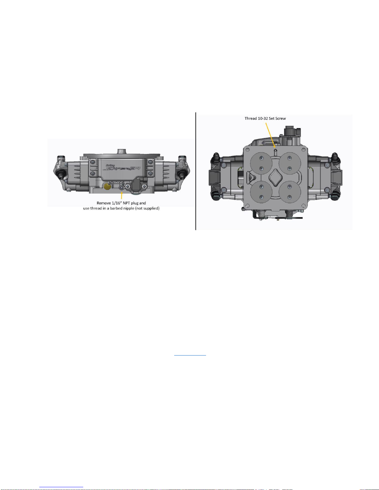
PREPARING THE THROTTLE BODY FOR INSTALLATION........................................................................................7
THROTTLE BODY INSTALLATION...............................................................................................................................7
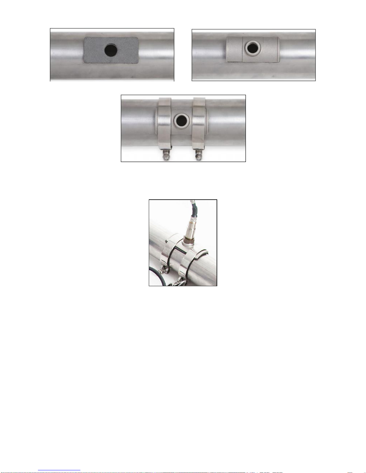
OXYGEN SENSOR INSTALLATION.............................................................................................................................8
COOLANT TEMPATURE SENSOR INSTALLATION....................................................................................................9
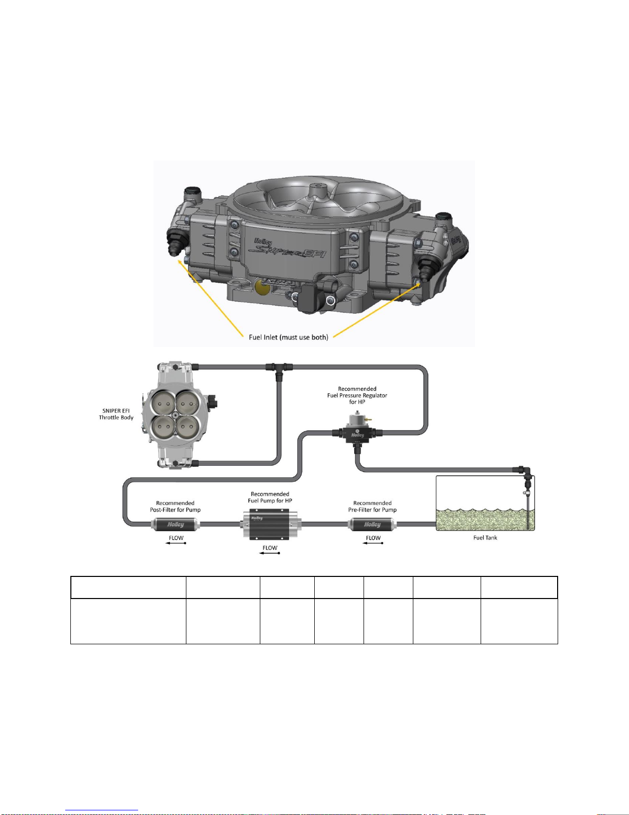
FUEL SYSTEM CONNECTIONS.................................................................................................................................10
ECU WIRING OVERVIEW...........................................................................................................................................11
BASIC WIRING INSTALLATION..................................................................................................................................12
GENERAL WIRING REFERENCE...............................................................................................................................13
Throttle Body Connections ......................................................................................................................................13
Pigtail & Loose Wire Connections............................................................................................................................13
Connecting Sniper EFI Touchscreen LCD to Sniper EFI.........................................................................................14
NON TIMING CONTROLLED IGNITION SYSTEM WIRING .......................................................................................17
Coil (-) [no timing control].........................................................................................................................................17
Ignition Box Tach Output (No Timing Control).........................................................................................................18
TIMING CONTROLLED IGNITION SYSYEM WIRING................................................................................................20
Timing Control Preface:...........................................................................................................................................20
MSD (Magnetic) Distributor [Timing Control] ...........................................................................................................20
Holley Dual Sync Distributor [Timing Control]..........................................................................................................25
Sniper EFI HyperSpark Distributor [Timing Control] ................................................................................................31
HANDHELD NAVIGATION ..........................................................................................................................................32
Possible Screens.....................................................................................................................................................32
INITIAL EFI SETUP .....................................................................................................................................................34
Calibration Wizards..................................................................................................................................................34
Sensor Verification...................................................................................................................................................38
Prestart Checklist.....................................................................................................................................................39
First Startup.............................................................................................................................................................39
After Startup.............................................................................................................................................................39
Ignition Timing Check (without Timing Control) .......................................................................................................40
Ignition Timing Check (ECU Controlling Timing)......................................................................................................41
THROTTLE BLADE ADJUSTMENT ............................................................................................................................42
SYSTEM SETUP .........................................................................................................................................................43
Ignition System Setup..............................................................................................................................................43
BASIC TUNING............................................................................................................................................................44
Basic Fuel................................................................................................................................................................44
Target AFR..............................................................................................................................................................45
Acceleration Enrichment..........................................................................................................................................45
Fuel Prime ...............................................................................................................................................................46
Closed Loop Enable/Disable ...................................................................................................................................46
Learn Enable/Disable ..............................................................................................................................................47

4
Basic Idle.................................................................................................................................................................47
Spark.......................................................................................................................................................................48
SYSTEM TUNING........................................................................................................................................................48
Outputs....................................................................................................................................................................49
Engine Setup...........................................................................................................................................................50
Sniper Setup............................................................................................................................................................50
Ignition Setup...........................................................................................................................................................51
Static Timing............................................................................................................................................................51
ADVANCED TUNING ..................................................................................................................................................52
IAC Rampdown........................................................................................................................................................54
Idle Spark ................................................................................................................................................................55
Idle Speed ...............................................................................................................................................................56
Advanced 2..............................................................................................................................................................56
SNIPER EFI MONITOR...............................................................................................................................................57
Monitors...................................................................................................................................................................57
Multi-Gauge.............................................................................................................................................................58
Changing Monitor Channel Scaling .........................................................................................................................58
Custom Configuring Dash 1 Dash 2 or Dash 3........................................................................................................60
NITROUS TUNING ON HANDHELD ...........................................................................................................................60
BOOST CONTROL ON HANDHELD...........................................................................................................................60
ADVANCED TABLES ON HANDHELD .......................................................................................................................61
TUNING DEFINITIONS................................................................................................................................................61
DATALOGGING & FILE TRANSFERS ........................................................................................................................70
Taking a Datalog with the 3.5” TSCLCD..................................................................................................................70
Triggering an Automatic Datalog .............................................................................................................................70
Changing Diagnostics Type of Datalog....................................................................................................................70
Downloading Global Configuration from Sniper EFI Throttle Body to SD card: .......................................................71
Loading Calibration into Sniper EFI ECU.................................................................................................................71
LAPTOP SUPPORT.....................................................................................................................................................72
Viewing Global Configuration with Sniper EFI Software without USB Cable: ..........................................................72
Viewing Datalog with Sniper EFI Software: .............................................................................................................73
TROUBLESHOOTING.................................................................................................................................................74
Troubleshooting Guide ............................................................................................................................................74
Sensor Verification...................................................................................................................................................74
Sensor Diagnostics and Statuses............................................................................................................................74

5
INTRODUCTION & SYSTEM REQUIREMENTS
Holley Performance Products has written this manual for the installation of the Sniper EFI TBI fuel injection system.
This basic manual contains the information necessary for the installation of the throttle body, wiring, and sensors.
Please read all the WARNINGS and NOTES, as they contain valuable information that can save you time and money.
It is our intent to provide the best possible products for our customer; products that perform properly and satisfy your
expectations.
Engine Requirements
Before moving forward with the installation, please verify your vehicle meets the engine and fuel system requirements
below:
Engine is in sound mechanical condition
Engine horsepower is between 800-1500
Engine is an 8 cylinder
Engine has a 4 barrel, 4500 style flange intake manifold*
Unleaded fuel only
Any RTV silicone sealants used on the engine are sensor safe
* Any 4500 flange intake manifold will work. Make sure to use proper gaskets to seal the throttle body to the intake
manifold and ensure that there are no vacuum leaks.
Fuel System Requirements
The Sniper EFI system requires a high pressure fuel pump capable of operating at 60 psi with at least 50 gallon per
hour of fuel flow (more fuel flow may be needed for higher horsepower engines). When selecting a pump, and lines, be
sure each component is designed to perform at high pressure. Holley offers a variety of fuel pumps, hoses and
accessories to complete your installation. For best results, Holley strongly recommends an in-tank pump. Installing the
fuel pump in the tank results in quieter operation, less chance of cavitation and a reduction in pump temperature. If
mounting the pump in the tank is not an option, install the pump as close as possible to the tank. Within 2-feet of
sending unit is recommended. Once the fuel system is installed checking the fuel pressure on the inlet side of the
Sniper EFI is recommended, fuel pressure needs to be between 55-65 PSI.
TOOLS REQUIRED FOR INSTALLATION
Standard Wrench Set Small Blade Screwdriver Allen Wrench Set
Medium Blade Screwdriver #2 Phillips Screwdriver Digital Voltmeter
Drill and Assorted Bit Sizes Terminal Crimping Tool
Factory Service Manual for your vehicle 7/8” Drill Bit (step-bit recommended)
An assistant is necessary for some installation and adjustment procedures and should be present for safety reasons.
WARNING! Before disconnecting the battery, we recommend locating a Clean Switched 12 volt ignition source.
This source needs to have 12 volts while cranking and with the key in the run position. Disconnect battery
before proceeding with any work to the vehicle.

6
PARTS IDENTIFICATION
ITEM #
IMAGE
DESCRIPTION
QTY
SERVICE P/N
NOTES
1
Bosch Wide Band
Oxygen Sensor
1
554-155
Use of leaded fuel will degrade sensor.
Prolonged use will require periodic
replacement.
Mounting procedure below is critical for system
performance
2
Clamp-on Oxygen
Sensor Bung
1
534-58
Requires 3/4” hole to be drilled
Mounting procedure below is critical for system
performance
In order to help prevent condensation in the
exhaust from damaging the sensor, ensure
that the sensor is installed with at least 10
degrees of vertical angle.
3
Coolant
Temperature
Sensor
1
543-120
3/8” NPT Threads – Adapters to ½” NPT are
available
Must be installed in a coolant passage in either
the intake manifold or cylinder head. Do not
install in thermostat housing.
4
Sniper EFI
Throttle Body
Assembly
1
N/A
4500 Flange Sniper EFI Throttle Body
Includes ECU, fuel injectors, Manifold Air
Pressure (MAP) sensor, Throttle Position
Sensor (TPS), Manifold Air Temp Sensor
(MAT), and an Idle Air Control Valve (IAC)
5
Air Cleaner
Gasket
1
Gaskets for mounting throttle body to intake
manifold
6
Open & 4 Hole
Flange Gaskets
1
7
3.5” Touch
Screen Controller
1
553-115
Includes harness to connect directly to CAN
connector
8
Output Harness
1
558-491
Mates to Input/Output connector on Main
Wiring Harness and can be used for A/C
Shutdown, Electric Fan #1 Output, and/or
Electric Fan #2 Output.
9
Main Harness
and Ignition
Adapter
1
558-490

7
PREPARING THE THROTTLE BODY FOR INSTALLATION
If the Sniper EFI will be used on a N/A engine, no changes need to be made to the throttle body.
Draw through Supercharger Applications: When using the Sniper EFI on a draw through boosted application (I.E.
positive displacement blower such as an 8/71), the throttle body must be converted to read manifold pressure from a
remote source that sees manifold pressure. To do this, remove the 1/16” NPT plug nearest the wires on the front of
the throttle body. Thread in a 1/16” NPT barbed nipple. Next, install the supplied 10-32 set screw into the machined
port on the bottom of the throttle body. It is also recommended to take a small punch and peen the casting around the
set screw in 2-3 places. The installation of this set screw is critical to system operation. Failure to do so will cause
false MAP sensor readings.
THROTTLE BODY INSTALLATION
1. Start by labeling all vacuum lines for easy identification, i.e. brake booster & vac advance for distributor. If any
lines appear damaged, now is the time to replace them. Next, remove the carburetor, clean the gasket mating
surface, and install the provided intake flange gasket on the intake manifold.
2. Place the Sniper EFI throttle body on top of the new flange gasket on the manifold. Using the correct length carb
stud and nuts, tighten the Sniper EFI throttle body down progressively in a “criss-cross” pattern (60-80 in.lbs.).
3. Install the throttle linkage to the Sniper EFI throttle body. Be sure to check for any binding conditions and correct
before proceeding. Poorly routed throttle cables & linkages can cause throttle pedal issues. The Sniper Stealth
4500 ships with the unit with a 1:1 throttle linkage. If desired the link between the secondary and primary linkage
levers can be moved to different holes on the primary lever. If the position is changed, the customer must
change settings in the calibration. See section “Sniper Setup” for directions how to change this.

8
OXYGEN SENSOR INSTALLATION
WARNING!
Failure to disconnect the AIR pump or locating the oxygen sensor downstream from AIR injection will result in an
extremely rich mixture, which could cause drivability problems and severe engine damage. If disconnecting AIR
pump, check with local ordinances for the legality of this procedure in your area.
Your vehicle may already have an O2 sensor bung welded into the exhaust. This bung location needs to be verified
before using it with the Oxygen sensor included in the Sniper EFI system. Ideally the bung will be 6-10 inches after the
collector for a true reading of all cylinders and have a minimum of 18” length past the sensor location. If the vehicle is
equipped with a catalytic converter, the bung must be between the engine and the catalytic converter. The bung also
must be on the top side of the tube so moisture cannot collect on the oxygen sensor. If there is an acceptable bung
already present, go ahead and tighten the oxygen sensor supplied with your Sniper EFI in the bung. If there is not an
acceptable bung already in the exhaust, please plug all poorly placed bungs and follow the following instructions for
the included Clamp-On O2 bung.
If needed, Hooker Blackheart offers different diameter Clamp-On O2 Bung kits:
2.25” Diameter: 71014303-RHKR
2.50” Diameter: 71014302-RHKR
3.00” Diameter: 71014301-RHKR
1. Locate a position for the oxygen sensor as close to the engine as possible. The oxygen sensor should be
mounted at a point where it can read a good average of all the cylinders on one bank. This would be slightly
after all the cylinders merge. If you have long tube headers, mount the sensor approximately 6-10” after the
collector. You must have at least 18” of exhaust pipe after the sensor.
2. If your vehicle has catalytic converters, the oxygen sensor MUST be located between the engine and the
catalytic converters. It is also CRITICAL that the oxygen sensor is NOT installed in the bottom of the exhaust
tube. This will help prevent condensation in the exhaust tubing from entering the sensor. The clamp-on kit
installation requires a 3/4 hole to be drilled in the exhaust system. Refer to main installation manual for more
details. NOTE: Verify that the O2 cable is supported correctly and away from heat sources such as the
exhaust. If the O2 cable has melted it is not something fixed under warranty and will require the
unit to be sent back to Holley to be repaired at customer cost.
3. Ensure the location for the sensor is at the angle in Figure 1. This will help prevent condensation in the exhaust
tubing from entering the sensor. The sensor can be mounted on either side of the tubing.
Figure 1
4. Mark the center of the casting on the exhaust tube and drill a 3/4" hole. Deburr the hole after drilling (Figure 2).
Figure 2
5. Place the gasket on the tube (Figure 3), then the casting on the tube (Figure 4). Slip a clamp on one side and
lightly tighten. Slip the second clamp on and lightly tighten (Figure 5). It is necessary to use a small amount of
anti-seize on the threads of the T bolt clamps to prevent thread damage.

9
Figure 3 Figure 4
Figure 5
NOTE: Never run the engine with the oxygen sensor installed if it is not plugged in and powered by the ECU, or it
will be damaged. If you need to plug the hole temporarily, use an O2 sensor plug or a spark plug with an
18mm thread.
COOLANT TEMPATURE SENSOR INSTALLATION
Install the Coolant Temperature Sensor into a 3/8” NPT coolant passage in either the intake manifold or cylinder head.
Do not overtighten or damage to the cylinder head or intake may occur. It is best to drain thesome of the coolant before
the sensor is installed. Use thread sealer or a small amount of thread tape. Do not install the sensor in the thermostat
housing, or in an area that will not see a constant flow of coolant.

10
FUEL SYSTEM CONNECTIONS
Connect fuel feed and return hose. It is mandatory to use an external fuel pressure regulator and feed both front and
rear fuel injector covers. Holley 12-848 or 12-851 are the recommended bypass fuel pressure regulator based on
how much HP the application makes. Reference Figure 3 & 4 for plumbing diagrams and recommended fuel system
components.
NOTE: Fuel pressure should be checked on the inlet fuel line before initial start up during the fuel pump prime. We
recommend Earl’s Part Number 100187ERL (0-100 psi Liquid filled gauge) & AT100199ERL (-6AN Gauge Adapter) to
check fuel pressure.
Fuel Fitting Overviews
HP Rating
Fuel Pump
Regulator
Pre
Filter
Post
Filter
Feed Line
Size
Return Line
Size
Up to 800 HP
12-1600
12-848
162-570
162-572
-6 AN
-6 AN
800 HP to 1000 HP
VR1 12-1500
12-851
162-577
162-575
-8 AN*
-8 AN*
Greater than 1000 HP
VR2 12-3000
12-851
162-577
162-575
-8 AN*
-8 AN*
*Use 3/4”-16 Male O-Ring to -8 AN Male Fitting, PN AT985008ERL, on the Sniper Throttle Body, Purchased Seperately
DANGER! Take precautions to ensure that all fuel components are away from heat sources, such as the
engine or exhaust pipes. A fire or explosion hazard could cause serious injury or death!
DANGER! Before disconnecting or removing fuel lines, ensure the engine is cold. Do not smoke.
Extinguish all open flames. An open flame, spark, or extreme heat near gasoline can result in a
fire or explosion causing property damage, serious injury, and/or death.
DANGER! Never get under a vehicle supported only by a jack. Serious injury or death can result from
vehicles falling off of jacks. Before working underneath a vehicle, support it solidly with jack
stands.

11
ECU WIRING OVERVIEW
The Sniper EFI throttle body comes with sensors pre-wired for easy installation. The illustrated diagram below is
intended as an overview of how the system should be wired. Remember, the main ECU power and ground must be
connected directly to the battery AFTER all other wiring installation has been performed.

12
BASIC WIRING INSTALLATION
The Sniper EFI throttle body has the following connectors and connections. Wires are labeled as well for
identification. Not all of these wires will always be used.The following is a main overview, with more detailed
installation information following.
7 Pin Connector –Main Sniper Wiring Harness: Mating Harness PN 558-490
Pin Color Labeled Name Function
E Red Battery Positive (+) Connects directly to battery positive terminal
G Black Battery Negative (-) Connects directly to battery negative terminal
C Blue Fuel Pump Output (+) +12v Fuel Pump Supply from Relay
A Violet Crank Signal Positive (+) Engine Speed Signal Input (see Ignition Wring Section)
B Dark Green Crank Signal Negative (-) Engine Speed Signal Ground (see Ignition Wiring section)
D Yellow Coil (-) Input Engine Speed Input (see Ignition Wiring section)
F Pink Switched Ignition (+12v) NOTE: must remain powered during cranking
10 Pin Connector –Mating Harness PN 558-491, 8 wires are populated. This connector contains:
Pin Color Labeled Name Function
A Orange Input #1 (-) Optional - Connect to a ground triggered A/C relay
B Yellow Input #2 (-) Optional - Connect to a programmable ground input
C Light Blue Output #1 (-) Optional –Connect to Fan #1 relay ground trigger
D Light Green Output #2 (-) Optional –Connect to Fan #2 relay ground trigger
E Grey Output #6 (-) Optional –Connect to ground side trigger of A/C shutdown relay
F White Points Output Used to trigger a CD ignition box or the included Coil Driver Module
G Dark Brown Tach Output Used to drive an aftermarket tachometer
H Tan Digital Gauge Output Used to drive Holley EFI analog gauges via 554-130 Gauge Module
8 Pin Connector –Mating Harness PN 558-492, 8 wires are populated.
Pin Color Labeled Name Function
A Orange Sensor Reference (+5V) Optional - +5V Supply for 0-5V Sensor
B Black Sensor Ground (-) Optional - Ground for 0-5V Sensor
C Violet Input #3 (5V) Optional - Programmable 0-5V sensor input
D Pink Input #4 (5V) Optional - Programmable 0-5V sensor input
E Dark Green Input #5 (5V) Optional - Programmable 0-5V sensor input
F Dark Blue Output #3 (-) Optional - Programmable ground output
G Dark Brown Output #4 (-) Optional - Programmable ground output
H Grey Output #5 (-) Optional - Programmable ground output
Touch Screen LCD Display –This small 4 pin CAN connector plugs into the Handheld Touch Screen display unit. Replacement
3.5” Touch Screen Handheld part number is 553-115.
Coolant Temperature Connector - Connects to coolant temperature sensor. Replacement Coolant Temperature Sensor part
number is 543-120.
Oxygen Sensor Connector -Connects to oxygen sensor. Replacement Oxygen Sensor part number is 554-155.
Pre-configured Inputs and Output wiring for Nitrous Wizard Calibrations
7 Pin Connector
Pin Color Labeled Name Function
E Red Battery Positive (+) Connects directly to battery positive terminal
G Black Battery Negative (-) Connects directly to battery negative terminal
C Blue Fuel Pump Output (+) +12v Fuel Pump Supply from Relay
A Violet Crank Signal Positive (+) Engine Speed Signal Input (see Ignition Wring Section)
B Dark Green Crank Signal Negative (-) Engine Speed Signal Ground (see Ignition Wiring section)
D Yellow Coil (-) Input Engine Speed Input (see Ignition Wiring section)
F Pink Switched Ignition (+12v) NOTE: must remain powered during cranking
10 Pin Connector –8 wires are populated. This connector contains:
Pin Color Labeled Name Function
A Orange Input #1 (-) Nitrous Master Enable –Switched ground trigger (Required)
B Yellow Input #2 (-) Nitrous Input #1 –Switched ground trigger (Required)
C Light Blue Output #1 (-) Optional –Connect to Fan #1 relay ground trigger
D Light Green Output #2 (-) Optional –Connect to Fan #2 relay ground trigger
E Grey Output #6 (-) Nitrous Relay Trigger - Ground side trigger for the Nitrous relay
F White Points Output Used to trigger a CD ignition box or the included Coil Driver Module
G Dark Brown Tach Output Used to drive an aftermarket tachometer
H Tan Digital Gauge Output Used to drive Holley EFI analog gauges via 554-130 Gauge Module

13
GENERAL WIRING REFERENCE
An EFI system depends heavily on being supplied a clean and constant voltage source. The grounds of an electrical
system are just as important as the power side.
Sniper EFI contains multiple processing devices that require clean power and ground sources. The wiring for them
must be installed in such a manner that they are separated from “dirty” power and ground sources.
DO’S
Install the main power and ground directly to the battery. To the POSTS/TERMINALS, not to any other place.
Keep sensor and crank signal (distributor) wiring away from high voltage or “noisy/dirty” components and wiring,
especially secondary ignition wiring (plug wires), ignition boxes, water pumps, fans and other associated wiring. It is
best that the plug wires not physically contact any EFI wires.
Properly crimp or crimp and solder any wire connections. Apply quality heat shrink over any of these connections.
It is critical that the engine has a proper ground connection from the battery to the chassis, and the battery to the
engine.
DON’TS
NEVER run high voltage or “noisy/dirty” wires in parallel (bundle/loom together) with any EFI sensor wiring. If wires
need to cross, try to do so at an angle.
Don’t use the electric fan outputs to directly power a fan. They must only trigger a relay.
Don’t use improper crimping tools.
Don’t use things like “t-taps”, etc. Use proper crimpers/solder and heat shrink.
It is never recommended to splice/share signal wires (such as TPS, etc.) between different electronic control units
(i.e. “piggyback”).
Don’t connect the red/white switched +12V wire to “dirty” sources, such as the ignition coil, audio systems, or 12V
sources connected to HID head lamps.
NEVER start an engine with a battery charger attached
Throttle Body Connections
1. 7 pin Connector –Connects to the included 558-490 main harness.
2. 10 pin Connector (optional) –Connects to included 558-491 I/O harness.
3. 8 Pin Connector (optional) –Connects to optional 558-492 Super Sniper I/O harness
4. Touch Screen LCD Display / USB Dongle –This small 4 pin CAN connector plugs into the 3.5” Handheld
Touch Screen display unit or the Sniper EFI Can to USB Dongle Communication Cable.
5. Coolant Temperature Connector –Connects to coolant temperature sensor.
6. Oxygen Sensor Connector –Connects to oxygen sensor.
Note: All connections on the Sniper system are unique and cannot be plugged into the wrong component.
Pigtail & Loose Wire Connections
1. Pink Wire = 12V Switched - Should be connected to a switched +12 volt power source. Power source
should only be active when the ignition is on. Make sure source has power when engine is cranking as well
(check with voltmeter). Not all sources apply power when the ignition switch is in “cranking” position. DO
NOT connect to a “DIRTY” source like an ignition coil!
2. Red Wire = Battery Positive –Connect directly to the battery post. This powers the Sniper EFI system.
3. Black Wire = Battery Negative –Connects directly to battery negative post.
4. Blue Wire (Optional) = +12v Fuel Pump Relay Power Output - Used to directly power a fuel pump (max
current 15A). Make sure to terminate blue wire properly if not utilizing blue wire to provide power to the fuel
pump.
The Sniper EFI throttle body has the following connectors and connections. Wires are labeled as well for
identification. Not all of these wires will always be used. The following is a main overview, with more detailed
installation information following.

14
Connecting Sniper EFI Touchscreen LCD to Sniper EFI
Connect the Sniper EFI Handheld to the main harness. This is a simple plug and play connection. If you are going to
permanently leave the handheld in the vehicle, you will need to find a factory grommet in your firewall to pass the
Display CAN bus connector through and secure the excess wire away from hazards. If no factory grommets can be
utilized we recommend installing one.
NOTE: If the 3.5” Touch Screen LCD Display needs to be unhooked from the Sniper EFI. Depress the
lock tab on the male side of the connector as show in the following pictures.

15
UNUSED WIRES
As you finish the installation of your Sniper EFI you will likely have unused wires. These wires need to be properly
taken care of before installation is considered complete or you may end up with problems down the road. You have
two options on how to properly handle these wires. The preferred option is to remove them from the connector and
insert a weather proof plug in their place. The second option is to shorten the wire and properly seal the end of it to
prevent shorting out.
Option 1: Pin Removal
Required tools:
Small flat head screw driver
Pin removal tool # 567-101
Procedure:
1. Use a small screwdriver or other prying tool to gently remove the protective cover from the back of the
connector. NOTE: Be careful not to over extend the tabs on the cover or it will not securely fasten during re-
installation.
2. Gently insert # 567-101 removal tool into the small slot above the pin on front of the connector. It should not
require much force and you should feel the tool bottom out solidly in the connector after roughly ¼”.
3. With the removal tool still inserted fully in the cavity gently pull on the wire to remove it.
4. If you will not be putting a sealed wire back in the cavity then you should now install one of the cavity plugs
supplied with tool 567-101.
5. Re-install protective cover on back of connector.
Insert pin
removal tool
here

16
Option 2: Trim and Wrap Wire
Required tools:
Wire cutters
Adhesive heat shrink tubing
Heat source (heat gun or other)
Procedure
1. Disconnect the battery terminals.
2. Cut the end of the wire so that there is no bare copper showing. NOTE: Make sure you leave enough length
on the wire that you will have room to crimp or solder it at a later date should the need arise.
3. Place a piece of adhesive lined heat shrink roughly 1” long over the wire.
4. With the heat shrink tubing placed so it is covering the wire with two thirds of its length apply heat to shrink
the tubing.
5. Give the heat shrink a small pull to verify that it is solidly attached.

17
NON TIMING CONTROLLED IGNITION SYSTEM WIRING
Coil (-) [no timing control]
This Yellow wire marked “Coil-” is an RPM input wire used for the following applications:
A stock type mechanical advance distributor with a stock inductive ignition coil. Examples of this would be
any older style points distributor.
A 1974-1981 GM large cap HEI or aftermarket replacement.
WARNING! Do NOT use this input if you are using an aftermarket Capacitive Discharge (CD) ignition system
such as a MSD, Mallory, or others. The ECU will be damaged if you connect to a capacitive
discharge type ignition coil.
NOTE: Using this input, the EFI will NOT control the ignition timing of the engine. The timing will be based on the
distributor initial, mechanical, and vacuum advance, just like it did with a carburetor.

18
Ignition Box Tach Output (No Timing Control)
This requires use of the Ignition Adapter / Purple Wire that comes packaged with the main
power harness.
If you are using an aftermarket Capacitive Discharge (CD) ignition system such as a MSD, Accel, or others,
you need to connect to the “Tach Out” connection or wire these systems provide. This is a 12 volt square
wave output.
OPTION 2 WIRING “Tach Out”:
CAUTION! NEVER connect any of the EFI wires to the coil on any CD type ignition system. The ECU will be
permanently damaged!
NOTE: Using this input, the EFI will NOT control the ignition timing of the engine. The timing will be based on the
distributor initial, mechanical, and vacuum advance, just like it did with a carburetor.

19
For additional instructions on how to setup a Sniper EFI using a CD ignition box, please reference this helpful video.
https://www.youtube.com/watch?v=1EFiTBQ9DvI

20
TIMING CONTROLLED IGNITION SYSYEM WIRING
Timing Control Preface:
MSD (Magnetic) Distributor [Timing Control]
Before beginning, please know the following:
You will need to lock out the advance on the distributor if it is not already done.
You will need an adjustable rotor (available from MSD.)
You will need a timing light.
You will need a mark on the balancer at 15 degrees before top dead center (BTDC). If your balancer is not already
marked, please follow step one in the distributor removal section to create a mark on your balancer using a paint pen.
Overview:
Sniper EFI can control timing using most common magnetic pickup distributors currently available (ex. MSD).
However, you may need to make several very simple changes to the distributor which are outlined in the following
section. It is very important that you “lock out” the advance built in to the distributor and install an adjustable rotor.
Not “locking out” the distributor and installing an adjustable rotor as outlined in these instructions can cause the
engine to run poorly or even cause engine damage.
NOTE: These instructions are directed toward MSD distributor installations. However, the same basic things need
to be done with any magnetic pickup distributor before being used with Sniper EFI.
DISTRIBUTOR REMOVAL:
1. Disconnect the Battery NEGATIVE (-) cable.
2. Disconnect the power and or ground connection at the coil/coils. Tape up any non-insulated power and
ground terminals to eliminate any chance of a short circuit.
3. Rotate the crankshaft in the direction of engine rotation until it reads 15 degrees before top dead center
(BTDC) on the compression stroke. Take the distributor cap off and make sure that the rotor is pointing to
cylinder #1. If not, rotate the crankshaft one full revolution (as the engine is not on the compression stroke).
4. If your balancer is not marked at 15 degrees, take a tape measure and measure from the 0 degree mark to
the following point (mark does NOT have to be exact):
Balancer Diameter
Distance
6”
3/4”
7”
15/16”
8”
1-1/16”
5. Remove spark plug wires and all other wiring/vacuum hoses from distributor.
6. Remove distributor hold-down. Lift the distributor upwards and remove.
The Sniper EFI has the ability to control the engines ignition timing. This is an optional feature and is NOT required
for proper functioning of the fuel injection. By implementing ignition timing control through the Sniper EFI, the
engine will have more precise control and an improved idle. Please refer to the following instructions on how to
use this feature.
Holley recommends that those who wish to use the Sniper’s timing control feature first get the engine running
without timing control. Splitting the timing control into a secondary process will add very little time to the total
install, but could significantly help with trouble shooting, should it be needed.
Table of contents
Other Holley Automobile Accessories manuals

Holley
Holley 0-80508S Guide

Holley
Holley EFI 6.86" Pro Dash User manual

Holley
Holley HOOKER 2253HKR User manual

Holley
Holley 526-24 User manual

Holley
Holley 2280 User manual

Holley
Holley 550-407 User manual

Holley
Holley Terminator Stealth EFI User manual

Holley
Holley Sniper EFI User manual

Holley
Holley NOS 02121NOS User manual

Holley
Holley MPI PRO-JECTION User manual