HOLTOP ERVQ-B150-1B1 H01 User manual

Technical Manual of
Wall Mounted Energy Recovery Ventilator
APPLIED TO
φ
ERVQ-B150-1B1(H01)
ERVQ-B150-1B1(H02)
Attention
Please read this manual carefully before using the equipment
Contents
Accessories List-----------------------------------------------------------------1
Safety Attentions---------------------------------------------------------------2
Product Introductions ----------------------------------------------------------3
Specifications and Operation Instructions-------------------------------------4
Operation Instructions-------------------------------------------------------4~7
WIFI Connection-------------------------------------------------------------8~9
Installation Instructions--------------------------------------------------10~12
Maintenance---------------------------------------------------------------13~14
Failure Diagnose---------------------------------------------------------------15
Contents

1
The package includes the following items. Please check when open the box:
1. Ventilator unit 1 set
2. Operation manual 1 piece
3. And the below listed parts
Accessories List
Installation panel
1 pc
Power cable
1 pc
Remote control
1 pc
OA and EA Side/Back
cover 2pcs
Air vent flange
2 pcs
Air inlet grille 1 pc
Rain proof cover
2pcs
Rubber sealing ring
2pcs
Back seal ring 2 pcs
Knock-on anchor bolt
5 sets
Screws M3x6
and Nut M3 8sets
Tapping screws
4pcs
PVC Ducts
2 pcs
Air outlet grille 1 pc
Side sealing ring
2 pcs
Back plate insulation
foam
Please read the following safety instructions before installation. And ensure that the unit is
installed correctly. Please observe all instruction in order to avoid any injury or damage to
equipment or property.
Don’t install in the place of flam-
mable gas leakage, the gathering
of leakage gas will cause fire acci-
dent.
After installation, non-
professional person move the
product privately will cause dam-
age to the equipment.
Please don't block the indoor out-
let and return air inlet so as to
avoid fan abnormalities. Be sure to turn off the power
before maintenance or contact
the electrical parts
Please don't operate the machine
with wet hands, especially plugs
and electrical parts.
Don't remove motor and circuit
board to avoid electric leakage.
Must use three-phase power
socket. Improper ground wire
connection may cause electric
shock.
!
Safety Attentions
The following symbols indicate potential
levels of caution.
The following symbols indicate compliance
which must be observed.
Situations with a risk or death
or serious injure
Not allowed or Stop
Situations with a risk of injury
or equipment damage. Must follow or obliged
!
This product is 220V ~ 50Hz power
supply and three-pin plug. Please
use suitable power supply.
Please use a clean soft cloth to
wipe the machine to avoid
scratch
This product is common residential
product. If used in special circum-
stances, please consult our tech-
nical staff first.
For daily turn off, please use the
touch screen controller. If not at
home for a long time, please cut
off the power to save energy.
Please follow the maintenance in-
structions in this manual: clean the
return air filter and total heat ex-
changer regularly; replace primary
filter and HEPA filter regularly
Please install the product in envi-
ronment where humidity smaller
than 85%; do not introduce fresh
air in poor environment area.
Fresh air outlet should be away
from the kitchen ventilator, gar-
bage dumps, pollution discharge
outlet, air conditioning outdoor
units.
!
!
2

Working Principle and Functions
The wall mounted energy recovery ventilator, which integrates air purification and energy
recover function. This product is made of supply fan, exhaust fan, heat exchanger, primary
filter, medium filter, activated carbon filter and HEPA filter at OA side, primary filter at RA
side. It has functions as below:
1, Fresh air purification: after the outdoor air driven by supply fan and go through the
primary filter, it will have energy exchange with the RA in the heat exchanger; and after
the fresh air further filtered by the HEPA filter, then sent to indoor; meanwhile, the EA fan
will exhaust the polluted air to the outdoor, so to improve the indoor air quality.
2, Energy recover: Usually the temperature difference between indoor and outdoor is very
large. When the indoor is under the comfortable temperature and humidity, it will increase
the burden of air conditioning system if we send the fresh air to indoor directly after filter-
ing. In order to avoid this situation, our ERVs are all equipped with heat exchanger, which
can recover the energy of EA and then recycle to OA, this function will greatly decrease
the loss of energy.
Dimensions (mm)
Product Introductions
3
Specification
User manual of the main interface of display screen
1.The upper left corner is the WIFI connection status,
devices that are not equipped with WIFI symbol do not display;
2. The upper right corner of the screen is the clock
or timing status.
3.The upper central part of the screen is the current
indoor CO2 concentration / PM2.5 value.
4.The lower left side of the screen is the current room
temperature and humidity values.
5.The lower right side of the screen is the current
operation speed of the device.
6.At the bottom of the screen are three adjustable
buttons.
7."Auto" "Manual" "Timing" "Sleep" "PURE-L" "PURE-M"
and "PURE-H" are mode indication.
Specification and Operation Instructions
Model ERVQ-B150-1B1(H01) / ERVQ-B150-1B1 (H02)
Airflow ( m3/h) 150
Volt (V) 220~240 IP Class IPX2
Filtration Capacity (%) 99 Frequency (Hz) 50
Temp. efficiency (%) 82 Noise dB(A) 36
Weight (Kg) 10 Input power(W) 35
Serial number Refer to the
ventilator body Dimensions (L*W*H)mm 660*450*155
4

Buttons function introduction:
1. Press the button “on/off” to turn on or off the machine;
2. After startup, touch the “Mode” button to switch mode: Auto, Manual, Timer, Sleep,
PURE L, PURE M, PURE H.
Remark:when the machine starts, default is “Auto” mode.
3. Under “Manual” mode, touch “Speed” button to select speed 1-8.
Explanation for all modes:
1. Under mode “Auto”, it will adjust supply air volume according to indoor CO2/PM2.5
range, corresponding speed as below:
Remark: To ensure sufficient indoor fresh air supply, the speed will rise automati-
cally after model “Auto” runs for some time, 5-10 minutes later it will recover to
previous speed. During this time, the screen shows different speed from above
chart.
CO2 value Status Operational speed
0≤CO2≤450 Excellent 1
450<CO2≤1000 Good 3
1000<CO2≤1500 Light pollution 5
1500<CO2≤2000 Medium pollution 7
>2000 Serious pollution 8
Operation Instructions
5
PM2.5 Value Status Operational speed
0≤PM2.5≤35 Excellent 1
35<PM2.5≤75 Good 2
75<PM2.5≤115 Light pollution 4
115<PM2.5≤150 Medium pollution 5
150<PM2.5≤250 Heavy pollution 7
PM2.5>250 Serious pollution 8
2. Under any mode, the unit will be switched to “Manual” mode when user presses “Speed”
button, then press “Speed” again to enter SA/EA fan setting. When “SA” flashes, press
“Speed” to set SA fan speed from speed 1-8 ; press “Mode” to switch to “EA” fan set-
ting “EA” flashes, then press “Speed” to set from speed 1-8 . After setting, press
“Mode” to save and exit, or the system will automatically save and exit after 15s.
3. “Timer” mode, should be controlled through the remote controller.
4. Under “Sleep” mode, the unit runs in speed 1, after 30s the screen luminance will be
half as normal.
5. Mode “PURE L”, “PURE M”, “PURE H” are to improve indoor air quality rapidly; The purifi-
cation performance is enhanced progressively for the 3 modes.
Operation Instructions
6
Combinations Function
Ventilator is on, long press “On/Off + Speed” 1. RESET WIFI
2. Clear connection information
Ventilator is on or off, long press “On/Off + Mode” Reset to EX-factory default setting
Ventilator is off, long press “On/Off” Set RS485 address
Button Combinations

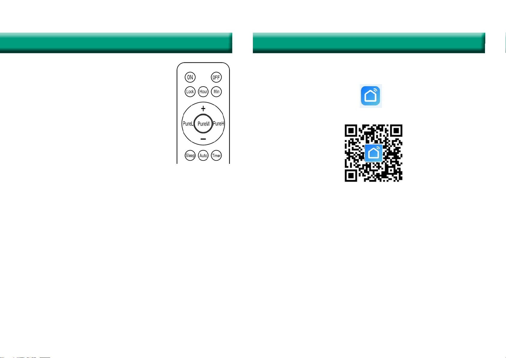
User manual of remote controller
Button function introduction:
1. Press “on” to turn on the ventilator.
2. Press “off” to turn off the ventilator.
3. Press “lock” to turn off the display,
Re-press again to turn on the display.
4. Press “Hour”, “Hour” part at the top right corner of the venti-
lator screen starts twinkling, then press “+” to increase time,
press “-” to decrease time, repress “Hour” button to save time
and exit.
5. Press “Minute”, “Minute” part at the top right corner of the
ventilator screen starts twinkling, then press “+” to increase
time, press “-” to decrease time, repress “Minute” button to
save and exit.
Remark: During twinkling, if no operation in 15s, twinkling ends and save setting
automatically.
6. Except for the status of time adjustment and being shut down, press "+" to change
speed range from small to large, press "-" to change air speed range from large to
small. Switching to “Manual” mode, the SA indicator flashes, press "+" or "-" to ad-
just the SA speed. After completing the SA speed setting, press “Pure H” switch to
the air speed selection of EA (Under this state, the “ Pure H” button is equivalent to
the “Mode” button), press "+" or "-" to adjust the air speed, after completing the EA
speed setting, press “Pure H” button again can exit the speed setting( or automatical-
ly exit without action for 15s), the air speed of SA and EA will be saved respectively.
7. The function of “Sleep” button is similar to “Sleep” button on ventilator.
8. The function of “Auto” button is similar to “Auto” button on ventilator.
9. Timer: Press “Timer”, timer mode starts, time at the top right corner of the machine
screen twinkles. Press “+” to increase time and “-” to decrease time in interval of 30
minutes, the longest timing is 8 hours, default timing is 00:00; Repress “Timer” button
to save and exit timer setting, top right corner of the ventilator displays current time
again.
Remark: During twinkling, if no operation in 15s, twinkling ends and save setting
automatically. After timer setting finished, if repress “Timer” button, top right
corner of the display shows remaining time for the timer setting, at this time it
is ok to set the timer again. To cancel timer function, set the time to 00:00.
10. The function of “PURE L”, “PURE M”, “PURE H” is similar to that on the ventilator.
Operation Instructions
7
Installation of “Smart Life”
1. If your phone is Android system, please search and download the APP of “Smart Life”
from Google play, while the IOS system can download it from the Apple App Store.
2. Or scan the below QR code to download.
Operation Instruction
1. Registration and log-in
If you do not have an account of “Smart Life”, please register and log in by following the
processes:
A. Click “agree” when “User Agreement and Privacy Policy” appear on the interface.
B. Click “Sign up” button, choose your country and enter your mobile number/email to
register, tick “I Agree User Agreement and Privacy Policy”, then click “Get Verification
Code” button, the phone you’re registering will receive a registration verification code;
C. Enter the verification code, fill in the password, you will get into the homepage of the
App or back to the log-in interface to log-in the app by using the account you registered.
2. Adding new device
A. Make sure your phone is connected to WIFI( 2.4G network only, does not support 5G
network or any others), click the “+” at the upper right corner in the homepage, entering
into network matching.
B. After entering, long press “On/Off + Speed” button when the ventilator is ON, until the
WIFI symbol on the display screen flashes. (Fast flashing refers to WIFI connection, slow
flashing refers to hotspot network.)
8
WIFI Function

C. Choose “Small Home appliance” in the network matching interface, slip downward to
find “Ventilation System (Zigbee), shown as below. After entering into WIFI network
matching interface, operate according to the instructions step by step, until network
matched successfully, please pay some patience during the network matching.
3. Controlling operation
Entering into the homepage of the App, click the “On/Off” button to control the running
status of the ventilator, click “Speed” button to adjust the airflow (Different models corre-
spond to different operations, please operate accordingly based on your purchased mod-
el).
4. Modify the device name
A. Click the symbol at the upper right corner in the homepage, enter into the homep-
age menu.
B. Click the symbol , entering into the setting interface, click “name” button to modify
your desired name, then click “Save” button.
5. Device authorization and sharing
A. The 1st person binding to the device enters into the device menu( as instructed on 4.
Modify the device name), then clicks “ device sharing”
B. Enter into the sharing menu, and enter the account number that you want to share,
click “Done”.
C. The shared user account appears on the menu if the sharing is successful.
6. Device deletion (unbinding)
A. Enter into the device menu( as instructed on 4. Modify the device name), then click
“device removing”.
B. Click “Removing Binding”, followed by “ confirm”, the device can be unbinding.
7. User information editing
A. Click “I” on the bottom right corner of the homepage.
B. Click on the picture above to enter the user information page
C. After entering into the user information page, you can modify the user information,
including avatar, user name (nickname, account number, and security, etc.)
8. Sign out
A. Click “Me” on the bottom right corner of the homepage, then click “setting” button.
B. Select "Sign out" at the bottom to logout.
9
WIFI Function
Installation Instructions
Ventilator installation
According to the project site to choose suitable installation location, Air inlet/outlet from
back or from the side.
Back installation
1. Choose the suitable location on wall, mark the
OA inlet and EA outlet location, also mark the 5
fixing holes of the installation panel on the wall
Attention:Ventilator bottom to the floor around 1.5 meters
Ventilator left and right side to the wall not less than 0.3 meter
2. To drill 2 holes on wall for fresh air inlet and exhaust air outlet, recommended size is
diameter 100mm, The 2 holes should face downward toward the outside to prevent any rain
water ingress. Recommended size for the 5 fixing holes is φ6x70mm, and input the 5 plastic
bolt Jacket into the holes
Attention: The OA inlet and EA outlet holes size is according to the Holtop acces-
sories (PVC pipes).
3. Connect the flange to the installation panel by M3X12 bolt and nut
4. According to the wall thickness, cut the suitable length of the PVC pipes, connect the
PVC pipes to the OA and EA accessories,
OA side: PVC pipe + Air inlet grille + Rain proof cover + Rubber sealing ring + Tapping
screws.
EA side: PVC pipe + Air outlet grille + Rain proof cover + Rubber sealing ring + Tap-
ping screws.
Remark: Holes of φ3mm need to be drilled in advance before installing the fixing
screw.
PVC pipe
Rubber sealing ring
Rain proof cover
Air inlet/outlet grille
Tapping screw
Tapping screw
10

5. Put the assembled ducts into the wall, ensure the
rain cover towards down, seal the gaps between the duct
and the wall.
6. Fix the installation panel on wall by the
knock-on anchor bolt .
7. The above installation is for “back installation” , so, need to cut the EPS “back cover” at the
OA vent as the below picture (DON’T cut the EPS side cover).
8. Put the 2 round OA and EA Side/Back covers on the side of the ventilator to cover the side
air inlet and side outlet. Paste the 10mm seal rings to the back of the air inlet and outlet.
9. Paste the back plate thermal insulated cotton/foam on the back
Of the ventilator if necessary (around the OA side), it helps avoid
the condensing water when the ventilator is used in cold area.
10. Hang the ventilator on the installation panel, user can adjust
the 4 pieces M5x18 hanging screws on the back of the ventilator to
suit the installation panel.
11. After the installation is completed, power on the ventilator.
Installation Instructions
seal the gaps
Cut the back cover when back
side installation
Cut the side cover
when side installation
11
Cut the back cover when
back side installation
Cut the side cover
when side installation
Installation Instructions
Side installation
1. Paste the 3mm side sealing rings on the flanges, connect the flanges to the ventilator
side by 8pcs M3x12 bolts and 8pcs M3 nuts. Be careful don’t let the nuts drop inside the
ventilator during installation.
2. This installation is for “side installation” , so, need to cut the EPS “side cover” at the OA
vent as the left picture (DON’T cut the EPS back cover), then cover the 2 round OA and EA
Side/Back covers to the back of the ventilator
3. Choose the suitable location on wall, mark the 5 fixing holes of the installation panel on
the wall, and mark the side OA inlet and EA outlet location of the side wall according to the
ventilator dimension
Attention:Ventilator bottom to the floor around 1.5 meters
Ventilator left and right side to the wall not less than 0.3 meter
4. Drill 5 fixing holes φ6x70mm (suggesting dimension) on the wall according the instal-
lation panel, then fix the installation panel on wall by the 5 Knock-on anchor bolts.
5. Drill 2 holes on wall for fresh air inlet and exhaust air outlet, recommended size is diameter
100mm, The 2 holes should face downward toward the outside to prevent any rain water
ingress.
Attention:When drilling the outlet hole on the wall, the opening hole size is only a
recommended value. When installing the ventilator by the side way, the ducts
should be flexible ducts( prepared by end-users), the hole size on the wall should
be finalized by the final used duct diameter.
12
Installation Instructions

OA and RA primary filter maintenance and change
HEPA filter change
6. Hang the ventilator on the installation panel, user can adjust the 4 pieces M5x18 hanging
screws on the back of the ventilator to suit the installation panel.
7. According to the wall thickness, cut the suitable length of the flexible pipes, connect the
pipes to the OA inlet grille and EA outlet grille, also the rain cover, etc. accessories same
like the “back installation”. Rain covers towards down.
8. Input the pipes to the wall, seal the gap between wall and the pipes by sealant.
9. Connect the another sides of the pipes to the flanges on side of the ventilator.
10. After the installation is completed, power on the ventilator
HEPA filter is at the top of the ventilator, as showed by
the right picture, it is used to filter the small particle that
less than 2.5μm in the air
- Open the covers according to the marks on the ventila-
tor, take out the HEPA filters and change to be the new
one.
- Recommended exchange period of the HEPA filter is 8 to
12 months.
OA primary filter and medium filter is at the side of the
ventilator while RA primary filter is at the bottom of the
ventilator, as showed by the right picture, used to filter
the large particle in the air.
- Open the covers according to the marks on the venti-
lator, take out the primary filters, medium filters.
- OA medium filter is not washable, It is advised to
change the filter every 1-2 months.
- OA and RA primary filters are washable, recommend-
ed to replace every 3-4 months.
OA primary filter
OA medium filter
RA primary filter
13
Attention: Before maintenance, the power must be cut off until the device com-
pletely stop, avoiding any injury.
Installation and Maintenance
Maintenance of motor and controller
Notice: Not for Non-professional, if any questions
please contact manufacturer.
Maintenance of heat exchanger
The plate heat exchanger is installed at the central right of the ventilator, it is the air to air
heat exchange device. It’s used to separate fresh air and exhaust air, effectively avoid
cross-contamination, and ensure that the cleanness of fresh air.
- Take off the ventilator from wall, unscrew the 6 pieces long screws from the back of the
ventilator, then to unscrew the access door and take out the plate heat exchanger.
- Clean the dust and dirt on the exchanger by vacuum cleaner
- It is recommended maintain or clean the exchanger every 3 years, for further help can
contact manufacturer.
14
Maintenance of PM2.5/CO2 sensor
In order to prevent the air quality sensor from being
blocked, the sensor needs to be cleaned regularly.
- Remove the bottom grid and take off the return air
primary filter.
- According to the right picture, use a hair dryer or
blower to clean the sensor, When using the hair dryer,
do not turn on the hot air.
Maintenance

User can make self trouble shooting following below chart in case of any failure.
Phenomenon Possible reasons Solutions
The display
doesn’t start up
1.Loosen or bad contact of power plug
2.Broken of power cable
3.Fault of display
1.Check if the plug is loosen
and reconnect it
2.Replace the power cable of
same specification
3.Contact manufacturer for
replacement
None or wrong
display of
temperature, hu-
midity or CO2 val-
ues
Sensor short circuit or open circuit Contact manufacturer for
service
Abnormal noise
1.The ducts connecting to machine are
not fixed.
2.Foreign matter goes inside the
Ventilator.
3.Fault of supply fan or exhaust fan.
1.Fix the duct
2.Contact manufacturer for
repair
Insufficient of fresh
air
1.Blockage of foreign matters at air
inlet/outlet.
2.Blockage of primary or HEPA filter.
1.Check and clear the foreign
matters
2.Clearn or replace the filters
Excess particles at
supply air outlet Overuse of primary and HEPA filters Replace the filters
No response to the
fan speed switch
(Code: E0, E1, E3)
1.No feedback from supply and ex-
haust fan
2.Fault of fans
3. Fault of main controlling board
1.Contact manufacturer for
repair
2.Contact manufacturer for
fan replacement
The PM2.5/CO2
value display ab-
normally or doesn’t
display
1. The PM2.5/CO2 sensor test probe is
covered by dust.
2. The sensor is short-circuited or
open.
Following the PM2.5/CO2
sensor maintenance method
in the manual to clean up
first, if not resolved, contact
the manufacturer for service.
Special declaration
The following situations are not included in the warranty.
1. Obvious man-made sabotage during usage.
2. Usage, maintenance and repair not following the instructions of this manual.
3. Damages caused from any force-major.
Failure diagnose
15
Failure Diagnose
This manual suits for next models
1
Table of contents
Other HOLTOP Fan manuals