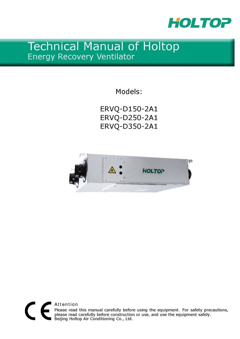
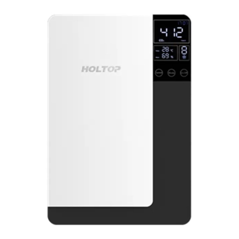
HOLTOP XHBQ-D2THA User manual

Models:
XHBQ-D2THA to XHBQ-D13THA
Technical Manual of Holtop
Energy Recovery Ventilator
Attention
Please read this manual carefully before using the equipment
Beijing Holtop Air Conditioning Co., Ltd.

5
Specifications
Model XHBQ-
D2THA
XHBQ-
D3THA
XHBQ-
D4THA
XHBQ-
D6THA
XHBQ-
D8THA
XHBQ-
D10THA
XHBQ-
D13THA
Airflow (m3/h)
L 150 250 350 500 700 900 1000
M 200 300 400 600 800 1000 1300
H 200 300 400 600 800 1000 1300
External
pressure (Pa)
L 60 75 80 89 92 80 75
M 70 82 85 92 96 85 85
H 75 85 88 97 100 86 90
Enthalpy
Eff.(%)
Cooling
L 60 62 62 63 57 60 58
M 55 57 57 59 55 58 56
H 55 57 57 59 55 58 56
Heating
L 63 65 65 67 63 64 62
M 59 61 60 61 57 62 59
H 59 61 60 61 57 62 59
Temp.Eff. %
L 75 73 74 76 74 76 76
M 70 68 69 70 68 70 70
H 70 68 69 70 68 70 70
Noise dB(A)
L 25 27 31 29 34 34 38
M 30 34 37 35 39 38 41
H 31.5 34.5 37.5 39 41 42 43
Voltage (V) 220 220 220 220 220 220 220
Current (A) 0.5 0.56 0.72 0.96 1.7 2.1 3.4
Input Power (W) 105 117 150 200 355 440 710
Net Weight (KG) 23 25 31 36 60 70 79

XHBQ-D2THA to D13THA Models
6
Dimensioned Drawings
Electric
Box
EA
OA
EA
OA SA
RA RA
SA
Electric
Box
Model A B C E F G I K M N
XHBQ-D3THA 599 744 100 675 657 19 315 111 270 Φ144
XHBQ-D4THA 804 744 100 675 862 19 480 111 270 Φ144
XHBQ-D6THA 904 824 107 754 960 19 500 111 270 φ194
XHBQ-D8THA 884 1116 85 1045 940 19 428 170 388 φ242
XHBQ-D10THA 1134 1116 85 1045 1190 19 678 170 388 φ242
XHBQ-D2THA 580 666 100 725 510 19 290 20 264 φ144
XHBQ-D13THA 1134 1116 85 1045 1190 19 678 170 388 φ242

Installation Considerations
Protect the unit to avoid dust or other obstructions entering the unit and accessories during installation,
or whilst in storage on site. Service ports should be installed to allow access for filter maintenance.
7
Installation Considerations
EA
RA
OA
SERVICE PORT
EA
SA RA
OA
SERVICE PORT
SA
Model A Inner ceiling
height B
XHBQ-D2THA 580 320
Model A Inner ceiling
height B
XHBQ-D3THA 599 320
XHBQ-D4THA 804 320
XHBQ-D8THA 884 450
XHBQ-D13THA 1134 450
XHBQ-D6THA 904 320
XHBQ-D10THA 1134 450
XHBQ-D8TZA 834 450
XHBQ-D10TZA 1216 450

天花板吊装螺杆
(Φ10-Φ12)
螺母
垫圈
吊装部件
垫圈
螺母
Suspending screw pole
Nut
Gasket
Suspending Part
Gasket
Nut
Installation Diagram
Fresh Air In Exhaust Air Out
Outside Fresh Air Duct
Insulation Discharge Duct
Suspending Pole
Fresh Air Duct
Exhaust Duct
Return Air Supply Air
Return Air
SupplyAir
Physical Installation
1.Installer to prepare suitable threaded hangers with adjustable nuts and gaskets.
2.Install as shown by the image above. Installation must be level and securely fastened.
3.Failure to observe proper fixing could result in injury, equipment damage and excessive vibration.
Uneven installation will also effect damper operation.
Notes for reverse installation of the unit
4.Reverse labeling shows the unit is upside down.
Ducting
1. Connection of unit vents and ducts should be taped or sealed to prevent air leakage, and should com-
ply to relevant guidelines and regulations.
2. The two outdoor vents should face downward toward the outside to prevent any rain water ingress.
(angle 1/100 1/50).
3. Insulation must be with the two ducts outside to prevent condensation.
Material: glass cotton, Thickness: 25mm
Installation Considerations
8
坡度1/100-1/50
Gradient1/100-1/50

1. Be sure the ceiling height is no less than the Figures in above table B column.
2. Unit must not be installed close to boiler flues.
3. Following phenomenon should be avoided in the ducting installation.
Serve bends Multiple reducers/ crimped duct
Multiple direction changes
4. Exessive use of flex-duct and long flex-duct runs should be avoided.
5. Fire dampers must be fitted as per national and local fire regulations.
6. Unit must not be exposed to ambient temperature above 40 and should not face an open fire.
7. Take action to avoid dew and frost.
As shown by drawing below, unit will produce dew or frost when saturation curve is formed from A to C.
Use pre-heater to ensure conditions are kept to right of the curve (B to B',to move C to C) to prevent
condensation or frost formation.
8. To avoid the outdoor exhaust air cycling back to indoor, the distance between the two vents installed
on the outside wall should be over 1000mm.
9.If heater is equipped to the unit, operation of heater should be synchronous with the unit, so that the
heater starts to work only when unit starts.
10.Duct muffler may be considered if user wants indoor noise to be minimized.
Installation Considerations
9

Power must be isolated during installation and before maintenance to avoid injury by electric shock. The
specifications of cables must strictly match the requirements, otherwise it may cause performance fail-
ure and danger of electric shock or fire.
Power supply is AC220V/50HZ/1 Phase. Open the cover of electrical box, connect the 2 wires (L/N/) to
the terminals and connect the cable of the control panel to the board according to the wiring diagram,
and join the control panel to the cable.
We do not accept any liability for any problems caused by the user’s self and non-authorized re-
engineering to the electrical and control systems.
10
Electrical Installation
Model Capacitor Power Supply Control Panel Model
XHBQ-D2THA, XHBQ-D3THA 1.5μF 450V AC
220V/1Ph/50Hz HDK-10 series
XHBQ-D4THA 3μF 450V AC
XHBQ-D6THA 3.5μF 450V AC
XHBQ-D8THA 8μF 450V AC
XHBQ-D10THA 10μF 450V AC
XHBQ-D13THA 7μF 450V AC
XHBQ-D8TZA 8μF 450V AC
XHBQ-D10TZA 10μF 450V AC
Model Spec. of power supply
cable
Spec. of normal controller
cable
XHBQ-D2THA
2x1.5mm2
XHBQ-D3THA
XHBQ-D4THA
XHBQ-D6THA
XHBQ-D8THA, XHBQ-D8TZA
XHBQ-D10THA,XHBQ-D10TZA
XHBQD13THA
2×0.5~1mm2

XHBQ-D2THA to D13THA
11
Wiring Diagrams
*
C02
QC
*
*S2
S1
COMM1
AN4
AN3
AN1 AN2
BGNDA12V
NL
PORT 1 PORT 2
PORT 3 PORT 4
CN2
94V0
CN5 CN4
CN6
CN7
CN3
LD3
LD4
RLY8
CN-EAFM
CN-SAFM
CM-DM
CN9
CN11
CN12
CN8
CN10
SW4 CN25
Control panel
RS485 ports
SA temp.
By-pass
FR(EA) temp.
OA temp.
RA temp.
Reserve switch
External switch
By-pass switch
Fire alarm signal input
Fault signal output
Running signal output
Exhaust fan
Supply fan
Voltage:220V-1ph-50/60Hz
Connect with heater or relay
Dial switch
M1
M2
GM
White
Joint of control panel and cable
Standard length: 5m
Connect the tin end of cable
to the port, no sequence
L
N
PE
Yellow
Black
Black
Black
White
White
Yellow
Yellow
Blue
Blue
Humidity
sensor
CO2sensor

Beijing Holtop Air Conditioning Co., Ltd
Factory address: No. 5 Yard, 7th Guanggu Street,
Badaling Economic Development Zone,
Yanqing District, Beijing, China
International Marketing Center
Address: Room 2101, Headquarter Center No. 25,
Tian An Hi-Tech Ecological Park,
No. 555 Panyu Ave, Guangzhou, China
Tel: 0086-20-39388201
Fax: 0086-20-39388202
Web: www.holtop.com
ISO9000 ISO14001 Issue Date: Feb 2020
This manual suits for next models
8
Table of contents
Other HOLTOP Fan manuals