holzkraft ASA Series User manual

Instruction Manual
Air Extraction Unit
ASA 1901 / 230V
ASA 1903 / 400V
ASA 2803 / 400V
ASA 1901
ASA 4303 / 400V
ASA 2803 / ASA 4303 ASA 7703
ASA 7703 / 400V

2ASA-Series | Version1.05
Imprint
Product identification
Air Extraction Unit Item number
ASA 1901 5128191
ASA 1903 5128193
ASA 2803 5128283
ASA 4303 5128433
ASA 7703 5128773
Manufacturer
Stürmer Maschinen GmbH
Dr.-Robert-Pfleger-Str. 26
D-96103 Hallstadt/Bamberg
Fax: 0049 (0) 951 96555 - 55
E-Mail: [email protected]
Internet: www.holzkraft.de
Indications regarding the operating instructions
Original instruction
Edition: 05.10.2020
Version: 1.05
Language: English
Author: FL
Copyright Information
Copyright © 2020 Stürmer Maschinen GmbH, Hallstadt,
Germany.
The contents of these operating instructions are the sole
property of the company Stuermer. Passing on as well
copying of this document, the use and distribution of its
content are prohibited if nit explicitly permitted. Contra-
ventions ere liable to compensation.
Subject to technical modifications and error.
Contents
1 Introduction ............................................. 3
1.1 Copyright ............................................................ 3
1.2 Customer service................................................ 3
1.3 Limitation of liability............................................. 3
2 Safety ....................................................... 3
2.1 Symbol explanation ............................................ 3
2.2 Personal protective equipment ........................... 4
2.3 Safety labels on the device................................. 4
2.4 Obligations of the operator ................................. 4
2.5 General safety rules............................................ 5
2.6 Residual risks ..................................................... 5
3 Intended Use ........................................... 5
3.1 Possible misuse.................................................. 6
4 Transport, packing, storage................... 6
4.1 Delivery and Transport ....................................... 6
4.2 Packaging........................................................... 7
4.3 Storage ............................................................... 7
5 Technical Data......................................... 7
5.1 Type plate ........................................................... 8
6 Description of the device ....................... 8
6.1 Scope of delivery ................................................ 9
6.2 Accessories ........................................................ 9
7 Assembly ................................................. 9
7.1 Installation Site ................................................... 9
7.2 Electrical connection......................................... 10
8 Operation ............................................... 10
8.1 Switch on .......................................................... 10
8.2 Switch off .......................................................... 10
8.3 Emptying the chip collecting bag ...................... 10
9 Care, maintenance and repair.............. 11
9.1 Maintenance .................................................... 11
9.2 Care after work ................................................. 12
9.3 Maintenance and repair.................................... 12
10 Emergency........................................... 13
11 Help with disturbances....................... 13
12 Disposal, recycling of used devices . 13
12.1 Decommissioning ........................................... 13
12.2 Waste disposal of electric equipment ............. 13
12.3 Disposal of lubricants...................................... 13
12.4 Disposal via municipal collection points.......... 13
13 Spare parts .......................................... 14
13.1 Ordering spare parts....................................... 14
13.2 Spare parts drawings...................................... 15
14 Electrical circuit diagrams ................. 19
14.1 Electrical circuit diagram ASA 1901 - 230V .... 19
14.2 Electrical circuit diagram ASA Series - 400 V .. 20
15 EC Declaration of Conformity ............ 21

Introduction
ASA-Series | Version1.05 3
1 Introduction
You have made a good choice by purchasing the HOLZ-
KAFT air extraction unit.
Read the operating manual thoroughly before com-
missioning the machine.
It gives you information about the proper commissioning,
intended use and safe and efficient operation and main-
tenance of your air extraction unit.
The operating manual is part of the air extraction unit
package. Always keep this operating manual in the loca-
tion where your air extraction unit is being operated. All
local accident prevention regulations and general safety
instructions for the operating range of your air extraction
unit must also be complied with.
1.1 Copyright
The contents of these instructions are copyright. They
may be used in conjunction with the operation of the air
extraction unit. Any application beyond those described
is not permitted without the written approval of Stuermer
Maschinen GmbH. For the protection of our products, we
shall register trademark, patent and design rights, as this
is possible in individual cases. We strongly oppose any
infringement of our intellectual property.
1.2 Customer service
Please contact your dealer if you have questions con-
cerning your air extraction unit or if you need technical
advice. They will help you with specialist information and
expert advice.
Germany:
Stürmer Maschinen GmbH
Dr.-Robert-Pfleger-Str. 26
D-96103 Hallstadt
Repair service:
Fax: 0049 (0) 951 96555-111
E-Mail: service@stuermer-maschinen.de
Spare part orders:
Fax: 0049 (0) 951 96555-119
E-Mail: ersatzteile@stuermer-maschinen.de
We are always interested in valuable experience and
knowledge gained from using the application-which then
could be shared and be valuable to develop our products
even further.
1.3 Limitation of liability
All information and notes in these operating instructions
were summarised while taking applicable standards and
rules, the state-of-the-art technology and our long-term
knowledge and experiences into consideration.
In the following cases the manufacturer is not liable for
damages:
- Non-observance of the operating instructions,
- Inappropriate use
- Use of untrained staff,
- Unauthorised modifications
- Technical changes,
- Use of not allowed spare parts.
The actual scope of delivery may deviate from the expla-
nations and presentations described here in case of spe-
cial models, when using additional ordering options or
due to latest technical modifications.
The obligations agreed in the delivery contract, the gen-
eral terms and conditions as well as the delivery conditi-
ons of the manufacturer and the legal regulations at the
time of the conclusion of the contract are applicable.
2 Safety
This section provides an overview of all important safety
packages for the protection of operating personnel as
well as for safe and fault-free operation. Other task-ba-
sed safety notes are included in the paragraphs of the in-
dividual phases of life.
2.1 Symbol explanation
Safety instructions
The safety notes in these operating instructions are high-
lighted by symbols. The safety notes are introduced by
signal words which express the concern of the risk.
DANGER!
This combination of symbol and signal words indi-
cates an imminently dangerous situation which may
lead to death or severe injury if not avoided.
WARNING!
This combination of symbol and signal words indi-
cates a potentially dangerous situation which may
lead to death or severe injury if not avoided.

4ASA-Series | Version1.05
Safety
Tips and recommendations
Observe the safety information in these operating in-
structions to minimise the risk of personal injury as well
as material damage and prevent hazardous situations.
2.2 Personal protective equipment
The personal protective equipment serves to protect per-
sons against impairments of safety and health while wor-
king. The staff member has to wear personal protec-tive
equipment while performing different tasks on and with
the machine which are indicated in the individual para-
graphs of these instructions.
The personal protective equipment is explained in the
following paragraph:
2.3 Safety labels on the device
The following safety labels and instructions are attached
to the air extraction unit (Fig. 1) and must be observed. .
Fig. 1: Safety signs
If safety labels on the machine are damaged or missing,
this can cause errors, personal injury and material dam-
age. The safety symbols attached to the machine must
not be removed. Damaged safety symbols must be re-
placed immediately.
As soon as the signs are not clearly visible and compre-
hensible at first glance, the machine must be stopped
until new signs have been attached.
2.4 Obligations of the operator
The operator of the extraction system must regularly
train his staff on the following topics:
- Observance and use of the operating and installa-
tion instructions, as well as the statutory provisions.
- Intended operation of the extraction system.
- Observe the instructions of the factory protection and
the operating instructions of the operator.
- Behavior in case of emergency.
CAUTION!
This combination of symbol and signal words indi-
cates a potentially dangerous situation which may
lead to slight or minor injury if not avoided.
ATTENTION!
This combination of symbol and signal words indi-
cates a possibly dangerous situation which may lead
to property and environmental damages if they are
not avoided.
NOTE!
This combination of symbol and signal words indi-ca-
tes a potentially dangerous situation which may lead
to material or environmental damage if not avoided.
Tips and recommendations
This symbol highlights useful tips and recommenda-
tions as well as information for an efficient and trou-
ble-free operation.
Ear protection
Ear protection protects the ears from hearing dam-
age caused by noise.
Breathing protection
The respirator mask serves to protect the respiratory
tract from the inhalation of dust particles.
Eye protection
Protective glasses protect the eyes against projected
parts and splashes of liquid.
Protective gloves
The protective gloves serve to protect the hands
against sharp components as well as against fric-tion,
abrasions or deep injuries.
Safety boots
Safety boots protect the feet from being crushed, fall-
ing parts and slipping over on slippery ground.
Protective clothes
Protective clothes are made of a tightly fitted fabric
without the protruding parts of low tear strength.

Intended Use
ASA-Series | Version1.05 5
2.5 General safety rules
1. Keep order in the work area. Disarray in work areas
easily leads to injuries.
2. Pay attention to the environment of the work area. Use
the exhaust system indoors only, and do not use it in
damp or wet places. Ensure good lighting of the work
area. Do not use the extraction system in the pre-
sence of flammable liquids or gases.
3. Protection against electric shock. Avoid contact with
grounded surfaces.
4. Keep other people away. Make sure that other people,
especially children who are not involved in the work,
do not touch the machine and stay away from the
work area.
5. Check the power cord regularly and have it repaired
by an authorized specialist if damaged.
6. Keep the handles dry, clean and free from oil and
grease.
7. Wear appropriate clothing. Do not wear loose hanging
clothes or jewelry. You can get caught up in moving
machine parts. Non-slip footwear is recommended at
work. Remove rings, watches and bracelets before
starting work.
8. Before starting work, make sure the suction hose is
securely fastened. Make sure that the setting key has
been removed before putting the machine into opera-
tion.
9. Ground the suction hose to dissipate the electrostatic
charge on the connecting piece of the machine to be
vacuumed.
10. Stay alert. Observe your own work, follow the com-
mon sense and do not use the machine when a
process seems dangerous.
11. Follow the local regulations for electricity and safety,
as well as the valid European standards. Check
whether the power supply meets the requirements of
the device (see type plate).
12. The device may only be switched on when fully as-
sembled.
13. Never pull on the cable to remove it from the power
outlet. Keep the cable away from heat, oil and sharp
edges.
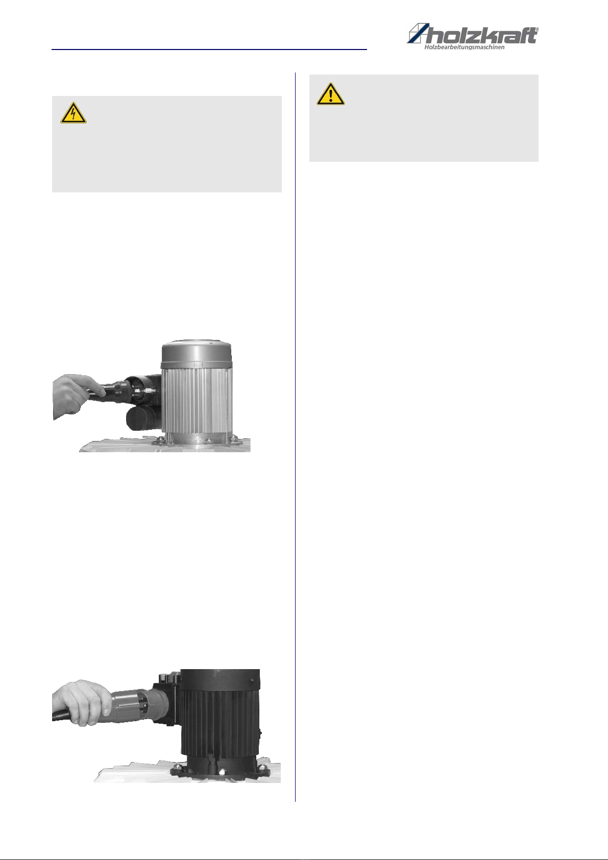
14. Maintenance work e.g. Bag, filter and hose change,
only with the power plug unplugged. There is a risk of
injury from touching the fan impeller.
15. Protect the device against moisture. If the machine is
operated outdoors, use only extension cords desi-
gned and labeled for outdoor use.
16. Do not operate in potentially explosive atmospheres.
17. Use only original accessories.
18. Check the device for perfect function before each
use.
19. Have defective switches replaced by an authorized
specialist.
20. Do not use the machine at temperatures below 0 ° C.
21. Observe accident prevention regulations and fire
protection regulations.
22. When changing the filter or chip bag, wear a dust
mask (filter mask with particle filter, filter class 2).
23. The use of accessories or accessories not recom-
mended in this manual may result in injury.
24. A guard or other item that is damaged should be pro-
perly repaired or replaced by an authorized service
center unless otherwise stated in this manual.
25. The machine complies with the relevant safety regu-
lations. Repairs may only be carried out by qualified
persons using original spare parts, otherwise signifi-
cant risks for the user may arise.
2.6 Residual risks
Dangers can arise from the extraction system if it is not
operated by trained persons and / or used improperly or
improperly.
Residual hazards are potential, non-obvious hazards,
such as:
- Injuries due to failure to observe the safety instructi-
ons, standards, guidelines or regulations
- Injuries caused by uncoordinated work,
- Danger from work on the electrical system, on the
cables and connections
There is a risk of crushing by the clamping lever when in-
stalling the chip bag.
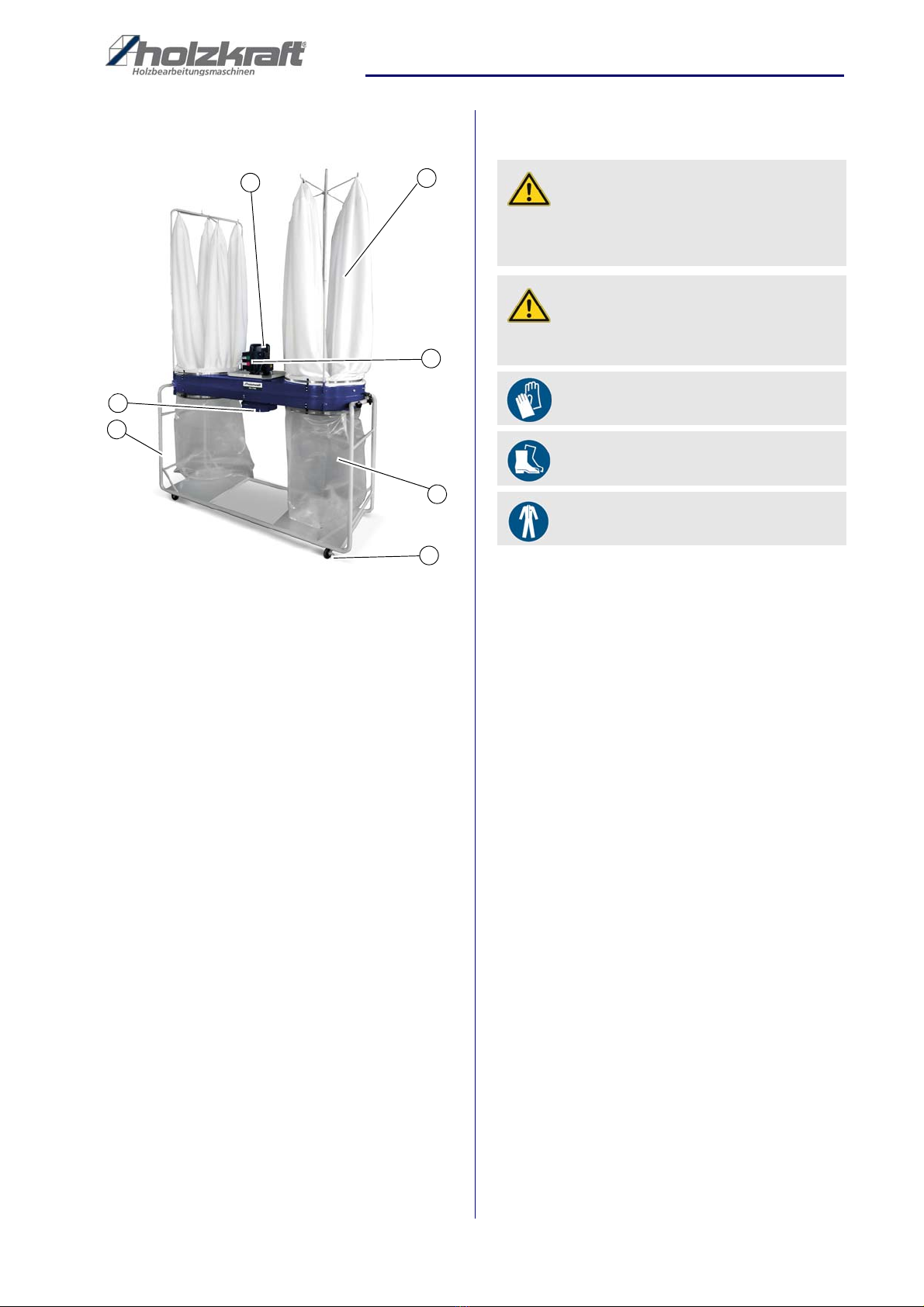
3 Intended Use
The extraction system was built exclusively for use in
combination with woodworking machines to extract mil-
ling, planing and sawdust (no dust). The extraction sy-
stem is used exclusively for extracting dry wood chips
from machine tools connected via a suction connection
or connected floor cleaning sets.
Solid bodies, e.g. Wood pieces (over an edge length of 1
cm) as well as metal parts and stones etc. must not be
vacuumed. Such bodies will damage the impeller (disc-
laimer of warranty).
WARNING!
When using a power tool, basic safety precautions
must always be taken to prevent the risk of fire,
electric shock and dangerous personal injury.
Read all of these instructions before working with the
machine and keep these instructions.

6ASA-Series | Version1.05
Transport, packing, storage
Proper use also includes compliance with all information
in this manual. Any use beyond the intended use or
otherwise is considered misuse. For structural and tech-
nical changes to the extraction system, the company
Stürmer Maschinen GmbH assumes no liability.
Claims of any kind due to damage due to improper use are
excluded.
3.1 Possible misuse
The air extraction unit may only be operated within the
technical data specified by the manufacturer. Any use
other than that described under "Intended use" is classi-
fied to be improper use. The manufacturer is not liable
for any resulting damage.
Possible misuse is e.g.
- The extraction system is not suitable for safety pur-
poses for the aspiration or extraction of explosive
or equivalent materials as defined in § 1, dust from
dust explosions classes St 2 and St 3, flammable
liquids and mixtures of flammable dusts with flam-
mable liquids
- No liquids, aggressive gases, flammable materials
or glowing particles (smoldering nests or similar)
should be sucked in. The extraction of woodwor-
king machinery that is subject to sparks and smol-
dering nests (for example multi-blade saws) is
prohibited.
- The extraction system is not intended for installa-
tion in an Ex area.
4 Transport, packing, storage
4.1 Delivery and Transport
Delivery
After delivery, check the extraction unit for visible trans-
port damage. If you notice any damage to the extraction
unit, report it immediately to the transport company or
dealer.
Transport
Improper transport is accident-prone and can cause da-
mage or malfunctions for which we do not grant any liabi-
lity or guarantee.
Transport the scope of delivery secured against shifting
or tilting with a sufficiently dimensioned industrial truck to
the installation site.
General risks during internal transport
WARNING!
Risk of misuse!
Misuse of the Air Extraction Units can lead to dange-
rous situations.
- Only operate the extraction system within the perfor-
mance range specified in the technical data.
- Do not operate the extraction system in potentially
explosive areas
- Never bypass or override the safety devices.
- Only operate the extraction system in a technically
perfect and fully assembled condition.
- Solid bodies, e.g. Wood pieces (over an edge length
of 1 cm) as well as metal parts and stones etc. must
not be vacuumed. Such bodies will damage the im-
peller (disclaimer of warranty).
WARNING!
Severe or fatal injuries may occur if parts of the
machine tumble or fall down from the forklift truck,
pallet truck or from the transport vehicle. Follow the
instructions and information on the transport box.
Note the total weight of the machine. The weight of
the machine is indicated in the "Technical data" of the
machine. When the machine is unpacked, the weight
of the machine can also be read on the rating plate.
Only use transport devices and load suspension gear
that can hold the total weight of the machine.
WARNING!
The use of unstable lifting and load suspension
equipment that might break under load can cause
severe injuries or even death. Check that the lifting
and load suspension gear has sufficient load-bea-
ring capacity and that it is in perfect condition.
Observe the accident prevention regulations issued
by your Employers Liability Insurance Association or
other competent supervisory authority, responsible
for your company.
Fasten the loads properly.
WARNING: DANGER OF TIPPING
The device may be lifted unsecured by a maximum
of 2cm.
Employees must be outside the danger zone, the
reach of loads.
Warn employees and, if necessary, advise employ-
ees of the hazard.

Technical Data
ASA-Series | Version1.05 7
Devices may only be transported by authorized and qua-
lified persons. Act responsibly during transport and al-
ways consider the consequences. Refrain from daring
and risky actions.
Gradients and descents (e.g. driveways, ramps and the
like) are particularly dangerous. If such passages are
unavoidable, special caution is required.
Before starting the transport check the transport route for
possible danger points, unevenness and disturban-ces
as well as for sufficient strength and load capacity.
Danger points, unevenness and disturbance points must
be inspected before transport. The removal of danger
spots, disturbances and unevenness at the time of trans-
port by other employees leads to considerable dangers.
Careful planning of internal transport is therefore essen-
tial.
4.2 Packaging
All used packaging materials and packaging aids are re-
cyclable and should be taken to a materials recycling de-
pot to be disposed of.
The delivery packaging is made of cardboard, so please
dispose carefully by having it chopped up and given to
the recycling collection.
The film is made of polyethylene (PE) and the cushioned
parts of polystyrene (PS). Deliver these substances to a
collection point for recyclable materials or to the waste
disposal company which looks after your region.
4.3 Storage
Thoroughly clean the individual functional parts in their
original packaging and the complete extraction system in
a dry, clean and frost-free environment (U-25 ° C - + 55 °
C). The extraction system must not be shut down with
chemicals in a room.
5 Technical Data
Type ASA 1901 ASA 1903
Length 1000 mm 1000 mm
Width / Depth 500 mm 500 mm
Height 2100 mm 2100 mm
Weight 39 kg 39 kg
Motor input 1,5 kW 1,5 kW
Motor output 1,05 kW 1,1 kW
Supply voltage 230 V 400 V
Rated volume
flow
1900 m³/h 1900 m³/h
Negative pres-
sure max.
1700 Pa 1700 Pa
Filter surface
area
1,92 m² 1,92 m²
Chip collection
volume
110 l 110 l
Ø Extraction duct
inlet outside
203 mm 203 mm
Ø Extraction duct
outlet outside
1x 100 mm
1x 120 mm
1x 100 mm
1x 120 mm
Idle speed 2950 min¯¹ 2950 min¯¹
Max. sound pres-
sure level
85,7 dB(A) 85,7 dB(A)
Type ASA 2803 ASA 4303
Length 1500 mm 1700 mm
Width / Depth 500 mm 600 mm
Height 2100 mm 2400 mm
Weight 53 kg 69 kg
Motor input 2,2 kW 3,8 kW
Motor output 1,68 kW 3 kW
Supply voltage 400 V 400 V
Rated volume
flow
2800 m³/h 4300 m³/h
Negative pres-
sure max.
1900 Pa 2000 Pa
Filter surface area 2x 1,92 m² 2x 2,4 m²
Chip collection
volume
2x 120 l 2x 215 l
Ø Extraction duct
inlet outside
203 mm 260 mm
Ø Extraction duct
outlet outside
1x 100 mm
2x 120 mm
2x 100 mm
2x 120 mm
Idle speed 2950 min¯¹ 2950 min¯¹
Max. sound pres-
sure level
87,5 dB(A) 89,9 dB(A)
Type ASA 1901 ASA 1903

8ASA-Series | Version1.05
Description of the device
5.1 Type plate
Fig. 2: Type plate ASA 1901
6 Description of the device
Illustrations in these operating instructions may dif-
fer from the original.
Air Extraction Unit ASA 1901 and ASA 1903
Fig. 3: Air Extraction Unit ASA 1901 and ASA 1903
Air Extraction Unit ASA 2803 and ASA 4303
Fig. 4: Air Extraction Unit ASA 2803 and ASA 4303
Type ASA 7703
Length 1900 mm
Width / Depth 670 mm
Height 2800 mm
Weight 88 kg
Motor input 4,8 kW
Motor output 3,8 kW
Supply voltage 400 V
Rated volume flow 7700 m³/h
Negative pressure max. 2800 Pa
Filter surface area 2x 5,98m²
Chip collection volume 2x 290 l
Ø Extraction duct inlet out-
side
260 mm
Ø Extraction duct outlet
outside
3 x 120 mm,
1 x 100 mm
Idle speed 2950 min¯¹
Max. sound pressure level 98,3 dB(A)
1
6
7
3
5
4
2
1
6
7
3
5
2
4

Assembly
ASA-Series | Version1.05 9
Air Extraction Unit ASA 7703
Fig. 5: Air Extraction Unit ASA 7703
1. Filter housing
2. ON / OFF switch
3. Chip bag
4. Swivel castor
5. Chassis housing
6. Suction unit
7. Engine
6.1 Scope of delivery
- Filter bag for ASA 1901/1903/2803
- Filter bag ASA 4303
- Filter bag ASA 7703
6.2 Accessories
- Filter cartridge 510x610 mm for ASA 4304
Item number: 5129990
- Filter cartridge 510x1220 mm for ASA 4303
Item number: 5129991
- Filter bag for ASA 1901 / 1903 / 2803
Item number: 5129190
7Assembly
The extraction system is delivered in individual parts. It
must be properly installed and used in strict accordance
with our instructions.
If the assembly is contrary to our regulations and the de-
fect / damage occurred is in a causal connection with an
improper modification, processing or other treatment, all
claims for damages or warranty are excluded. The custo-
mer has to prove that the improper installation was not
the cause of the defect.
7.1 Installation Site
The substrate at the place of installation for the extrac-
tion system must be level and firm.
There must be sufficient space available for operation
and maintenance of the extraction system.
Space requirements and wall clearances for main-
tenance and servicing must be observed during installa-
tion. The requirements for fire and explosion protection
must be observed in particular.
The grounding of all components must be carried out by
the customer.
1
7
5
6
3
4
2
WARNING!
Installation, electrical connection, supply connection,
maintenance, commissioning, repair, etc. may only
be carried out by trained specialist personnel.
ATTENTION!
Risk of injury!
Despite optimized manufacturing processes, there is
a residual risk of injury from cutting edges.
Wearing safety gloves!
Wear safety shoes!
Wear protective clothing!

10 ASA-Series | Version1.05
Operation
7.2 Electrical connection
230 V electrical connection (Fig. 6):
1 Ph/50 Hz
0,75 kW Fuse 10 A
1,1 kW Fuse 10 A
Connection via switch Plug combination (appliance eart-
hed plug). Use connection cable with standard Schuko
coupling, min. 1 mm cross-section.
Electrical connection via connecting cable 3-pole (230 V)
Fig. 6: 230V connection
400 V electrical connection (Fig. 7):
0,75 kW Fuse 10 A
1,5 KW Fuse 10 A
2,2 kW Fuse 10 A
Connection via switch-plug combination
(16 A, 5-pin CEE device Schuko plug).
Connection cable with usual 16 A 5-pin, use CEE cou-
pling, min. 1 mm2 cross section. Electrical connection
via connection cable 5-pole Do not use defective
connection cables! Check connection cable regularly for
damaged areas!
Fig. 7: 400V-Connection
8Operation
8.1 Switch on
- Check that the suction hose is firmly connected to
the extraction unit and to the extraction adapter of
the woodworking machine.
- Check. that the chip bags are well fastened.
- Switch on the extraction system by pressing the
green button "I"
- Turn on the woodworking machine.
8.2 Switch off
- Switch off the woodworking machine.
- Switch off the extraction system by pressing the red
"O" button.
8.3 Emptying the chip collecting bag
- Check and empty the chip collecting bag regularly.
ATTENTION: Pull out the mains plug!
- Hold the filled chip bag with one hand.
- Open the quick release device.
- Remove the bag and dispose of the contents in an
environmentally friendly way.
- Put the bag back in the holder and secure it with
the quick release device.
DANGER!
Danger of electrocution!
Contact with live components may cause mortal dan-
ger. Switched on electrical components can cause
uncontrolled movements and lead to serious injuries.
- Disconnect the mains plug before starting any adju-
stments to the extraction system.
DANGER!
- If the direction of rotation is wrong, there is a risk of
overloading the motor.
- The current consumption must not exceed the spe-
cified rated current.

Care, maintenance and repair
ASA-Series | Version1.05 11
9 Care, maintenance and repair
9.1 Maintenance
General:
The unit is designed for the extraction of dry dust and
chips in dust class L.
1.Clean the filter when the extraction capacity falls due to
the filter being blocked with dust.
2.Change the chip sacks promptly.
3.Only use original chip sacks
4. Check the direction of rotation occasionally- compare
the outfeed motor cooling fan with the directional ar-
row). If the direction of rotation is incorrect, the capa-
city will be inadequate and the motor will suffer exces-
sive heat generation. Only have the rotating field chan-
ged by a trained electrician.
Disposal of collected goods
When the filling container is full or when the maximum
permitted level is reached:
Step 1: Turn off the dust generating machine and unplug
the power cord.
Step 2: Carry out the cleaning again.
Step 3: Turn off the exhaust system and disconnect the
power plug.
Step 4: After loosening the tension levers, lower the
filling tank and pull out to change the chip bag.
Step 5: Carefully close the chip bag and remove it from
the container.
Step 6: Insert the new chip bag into the container.
Changing the filter bag
Step 1: Hook the loop of the filter bag into the holding rod
of the extraction system.
Step 2: Mount the extension bar to the end of the filter
bag holding bar. Lift the support rods with the fil-
ter bag attached and insert the end of the sup-
port rods into the holes in the bracket. NOTE:
The flared end of the filter bag extension pre-
vents the rod from sliding through the bracket.
DANGER!
- After switching off the device, the impeller continues
to run for approx. 1 to 3 minutes.
- Never brake the impeller by hand or with objects.
- If the device is out of operation for more than 1
week, it is generally necessary to rotate the motor
shaft and fan shaft once a week in order to avoid
punctual loading of the bearings and thus bearing
damage.
- Before putting the extraction system into operation,
the sealing of all installed filters must be checked.
ATTENTION!
- Danger of motor overload if the direction of rotation
is wrong.
- Current consumption must not exceed the specified
rated current.
- Maximum motor speed must not be exceeded.
- Maximum fan speed must not be exceeded.
DANGER!
- Fans must not be operated in the event of unusual
vibrations and noises or inadmissibly high vibration
speeds.
- Operation with inadmissibly high vibration values
can result in impeller breakage, which can lead to
serious material damage and personal injury.
Wear breathing protection!
(Filter mask with particle filter; fil-
ter class 2)
DANGER!
- Disconnect the power plug before pulling out the
collection containers.
- There is a risk of crushing by the clamping lever
when installing the filling container.
NOTE!
Disposal must be in accordance with local regulations.
DANGER!
Danger of electrocution!
Contact with live components may cause mortal dan-
ger. Switched on electrical components can cause
uncontrolled movements and lead to serious injuries.
- Disconnect the mains plug before starting cleaning
and maintenance work.

12 ASA-Series | Version1.05
Care, maintenance and repair
Step 3: Position the open end of the filter bag over the
upper lip of the support drum. Pass the locking
strap through the filter bag and secure it with the
clamp.
Step 4: Pass the remaining fastener tape through the lo-
ops of the dust collection bag. Position the open
end of the dust bag over the lower lip of the drum
and secure it with the locking clamp. NOTE:
Make sure that the locking strap is positioned in
the drum holder channel before locking the
clamp.
9.2 Care after work
The air extraction unit must always be kept in a clean
condition.
Step 1: Unplug the power cord from the wall outlet.
Step 2: Sweep or wipe all open machine parts with a
broom or cloth at regular intervals.
Step 3: All painted surfaces should be cleaned with a
soft, damp cloth.
Step 4: Treat bare metal work surfaces with anti-rust
spray.
9.3 Maintenance and repair
Daily:
- Visual inspection for obvious defects or damage to
the device or parts.
- The filter chamber should be checked for unusual
deposits and cleaned if necessary.
Monthly:
The monthly inspection is carried out by a qualified per-
son, i. someone who has been instructed in the opera-
tion of the suction device to perform.
- Clogged filter bags are to be cleaned.
- Visual inspection for obvious defects or damage to
the device or parts.
- The housing should be checked for unusual depo-
sits and cleaned if necessary.
- Check for leaks.
- Defective filter bags must be replaced.
Yearly:
The annual inspection is carried out by a competent per-
son, i. someone who has undergone maintenance trai-
ning.
- Clogged filter bags are to be cleaned.
- Visual inspection for obvious defects or damage to
the device or parts.
- The filter chamber must be checked for unusual
deposits and cleaned if necessary.
- Over their entire service life, the filters must have
the separation efficiency corresponding to the filter
class. In case of noticeable contamination or leaks,
the filter must be replaced.
- Check all seals for damage and tight fit, replace if
necessary.
- Defective filter bags must be replaced.
- Check the tightness of the housing and the contai-
ner and seal if necessary.
- Check fan chambers for dust deposits and clean if
necessary.
- Check bearings for unusual noises and relubricate
if necessary.
- Suction power control.
- Check the fan for dirt, vibrations, damage, loose
screws and corrosion. Every 12 months check im-
peller, in particular welds, for possible cracking.
If the Air Extraction Unit does not work properly, contact
a dealer or our customer service. The contact details can
be found in chapter 1.2 Customer Service.
Use protective gloves!
NOTE!
Never use harsh cleaning agents for cleaning. This
can lead to damage or destruction of the device.
ATTENTION!
Maintenance and repair work may only be carried out
by qualified personnel.
ATTENTION!
Monthly and annual inspections must be documented
in writing with the following content:
- Date of inspection
- Name of the examiner
- Note on the condition of the extraction system and,
if applicable, the indication of defects

Emergency
ASA-Series | Version1.05 13
10 Emergency
- In case of fire the device must be de-energized by
means of mains plug.
- The rooms should be closed to minimize the supply
of air.
- Alert fire department.
- Only open the housing after a safe wiping out of all
smoldering nests.
11 Help with disturbances
As a rule, the specialist dealer must be notified of
troubleshooting. Too low a flow rate may be due to the
blockage of the filter. To remedy this obstruction, the
ASA extraction system must be switched off. Then the
operator should tap the filter by hand to remove the dust
from the filter.
12 Disposal, recycling of used
devices
Please take care in your own interest and in the interest of
the environment that all component parts of the machine
are only disposed of in the intended and permitted way.
12.1Decommissioning
Immediately decommission disused machines in order to
avoid later misuse and endangering of the environment
or personal safety.
Step 1: Remove all environmentally hazardous fluids
from the old unit.
Step 2: If necessary, dismantle the machine into mana-
geable and usable assemblies and components.
Step 3: Guide the machine components and operating
materials to the appropriate disposal routes.
12.2Waste disposal of electric equip-
ment
Please note that electrical devices contain a variety of re-
cyclable materials as well as environmentally harmful
components.
You contributes to that these components are disposed
of separately and properly. In case of doubt, please con-
tact your municipal waste disposal. As necessary, a spe-
cialized waste disposal company can help be used for
the treatment.
12.3Disposal of lubricants
Please pay attention to an environmentally friendly dis-
posal of the used coolants and lubricants.
Observe the disposal instructions of your municipal dis-
posal companies.
Disposal notes for used lubricants are available from the
manufacturer of the lubricants. If necessary, request the
product-specific data sheets.
12.4Disposal via municipal collection
points
Disposal of used electrical and electronic equipment
(Applicable in the countries of the European Union and
other European countries with a separate collection sys-
tem for these appliances).
The symbol on the product or its packaging indi-
cates that this product should not be treated as normal
household waste, but must be returned to a collection
point for the recycling of electrical and electronic equip-
ment. By helping to properly dispose of this product, you
are protecting the environment and the health of others.
Environment and health are endangered by improper
disposal. Material recycling helps to reduce the con-
sumption of raw materials. For more information about
recycling this product, contact your local community, mu-
nicipal waste management, or the shop where you pur-
chased the product.
DANGER!
All protective and safety equipment must be reinstal-
led immediately after repair and maintenance work
has been completed.
DANGER!
To protect against potentially released pollutants, the
rooms may only be entered with respiratory masks.
DANGER!
Diagnosis, troubleshooting and recommissioning may
only be carried out by authorized persons. This is
especially true when working on electrical equipment
within the electrical wiring (such as testing, replace-
ment, etc.)!

14 ASA-Series | Version1.05
Spare parts
13 Spare parts
13.1Ordering spare parts
Spare parts are available from authorised retailers or di-
rectly from the manufacturer. The contact details have
been listed in section 1.2 Customer service. Always
quote the following key data with your spare parts or-
ders:
- Device type
- Serial number
- Quantity
- Designation
- Desired shipping type (post, freight, sea, air,
express)
- Shipping address
Spare parts orders without the aforementioned data can-
not be taken into account. The supplier shall determine
the shipping type if no relevant data was provided.
Information on the device type, item number and year of
manufacture can be found on the type plate attached to
the device.
Example
The engine for the Air Extraction Unit ASA 1901 must be
ordered. The engine has the number 2 in the spare parts
drawing 1.
By ordering spare parts, send a copy of the spare parts
drawing (1) with the marked part (engine) and marked
positon number (2) to the dealer or spare parts depart-
ment and provide the following information:
- Type of device: Air Extraction Unit ASA 1901
- Item number: 5128191
- Drawing number: 1
- Position number: 2
Item number of your device:
ASA 1901 5128191
ASA 1903 5128193
ASA 2803 5128283
ASA 4303 5128433
ASA 7703 5128773
DANGER!
Danger of injury by the use of
wrong spare parts!
Dangers may result for the user and damages as well
as malfunctions may be caused by using wrong or
damaged spare parts.
- Only use original spare parts of the manufacturer or
spare parts admitted by the manufacturer.
- Always contact the manufacturer in case of uncer-
tainties.
Loss of warranty!
The manufacturer's warranty will become null and
void if non-permissible spare parts are used.

Spare parts
ASA-Series | Version1.05 15
13.2 Spare parts drawings
The following drawings should help in case of service to identify necessary spare parts. To order, send a copy of the part
drawing with the parts marked to your authorized dealer.
13.2.1Spare parts drawing ASA 1901 and ASA 1903
Fig. 8: Spare parts drawing ASA 1901 and ASA 1903

16 ASA-Series | Version1.05
Spare parts
13.2.2Spare parts drawing ASA 2803
Fig. 9: Spare parts drawing ASA 2803

Spare parts
ASA-Series | Version1.05 17
13.2.3Spare parts drawing ASA 4303
Fig. 10: Spare parts drawing ASA 4303

18 ASA-Series | Version1.05
Spare parts
13.2.4Spare parts drawing ASA 7703
Fig. 11: Spare parts drawing ASA 7703

Electrical circuit diagrams
ASA-Series | Version1.05 19
14 Electrical circuit diagrams
14.1Electrical circuit diagram ASA 1901 - 230V
Fig. 12: Electrical circuit diagram ASA 1901 - 230 V

20 ASA-Series | Version1.05
Electrical circuit diagrams
14.2Electrical circuit diagram ASA Series - 400 V Models
Fig. 13: Electrical circuit diagram ASA Series - 400 V Models
Other manuals for ASA Series
1
This manual suits for next models
4
Table of contents