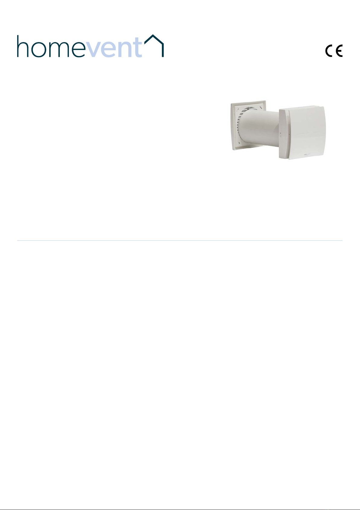
Installation &
Maintenance Manual
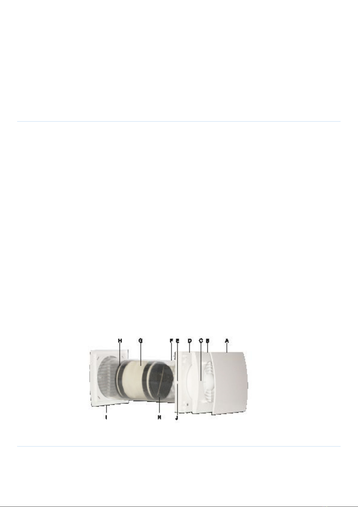
MORI HR NEXT
Alternate Flow Supply & Extract
Fan with Heat Retention
Read this manual carefully before using the product and keep it in a
safe place for reference.
This product was constructed up to standard and in compliance with regulations
relating to electrical equipment and must be installed by technically qualified
personnel. The manufacturer assumes no responsibility for damage to persons or
property resulting from failure to observe the regulations contained in this booklet.
PRECAUTIONS FOR INSTALLATION, USE & MAINTENANCE
• The device should not be used for applications other than those specified in this manual.
• Aer removing the product from its packaging, verify its condition. In case of doubt, contact a qualified technician. Do not leave packaging
within the reach of small children or people with disabilities.
• Do not touch the appliance with wet or damp hands/feet.
• This appliance can be used by children aged from 8 years and above and persons with reduced physical, sensory or mental capabilities or lack of
experience and knowledge if they have been given supervision or instruction concerning use of the appliance in a safe way and understand the
hazards involved. Children shall not play with the appliance. Cleaning and user maintenance shall not be made by children without supervision.
• Do not use the product in the presence of inflammable vapours, such as alcohol, insecticides, gasoline, etc.
• If any abnormalities in operation are detected, disconnect the device from the mains supply and contact a qualified technician immediately. Use
original spare parts only for repairs.
• The electrical system to which the device is connected must comply with regulations.
• Before connecting the product to the power supply or the power outlet, ensure that:
- the data plate (voltage and frequency) correspond to those of the electrical mains
- the electrical power supply/socket is adequate for maximum device power. If not, contact a qualified technician.
• The device should not be used as an activator for water heaters, stoves, etc., nor should it discharge into hot air/fume vent ducts deriving from
any type of combustion unit. It must expel air outside via its own special duct.
• Operating temperature: -20°C up to +50°C.
• The device is designed to extract clean air only, i.e. without grease, soot, chemical or corrosive agents, or flammable or explosive mixtures.
• Do not leave the device exposed to atmospheric agents (rain, sun, snow, etc.).
• Do not immerse the device or its parts in water or other liquids.
• Only turn off the power supply to the unit whenever a malfunction is detected or in the case of inspection, cleaning or maintenance. Prolonged
and/or repeated power interruption to the unit (any period more than 72 hours) can create a health and safety.
• For installation an omnipolar switch should be incorporated in the fixed wiring, in accordance with the wiring regulations, to provide a full
disconnection under overvoltage category III conditions (contact opening distance equal to or greater than 3mm).
• If the supply cord is damaged, it must be replaced by the manufacturer, its service agent or similarly qualified persons in order to avoid a hazard.
• Do not obstruct the fan or exhaust grille to ensure optimum air passage.
• Ensure adequate air return/discharge into/from the room in compliance with existing regulations in order to ensure proper device operation.
• If the environment in which the product is installed also houses a fuel-operating device (water heater, methane stove etc., that is not a “sealed
chamber” type), it is essential to ensure adequate air intake, to ensure good combustion and proper equipment operation.