Honeywell WP230A-M Mounting instructions

Honeywell
CONTENTS
Introduction....................................................................
2
Maintenance Schedule
.............................................................
2
Maintenance
....................................................................
2
Troubleshooting
................................................................. 4
Repair ........................................................................
7
Parts List.........................................................................
10
Ordering Information. .............................................................
14
WP240 Wiring Diagrams
............................................................
14
WP250
Refrigeration Drier Operation Check, .............................................. 16
Data Tables ....................................................................
17
Rev. 7-77
J.R.W.
Form Number 75-7131
Commercial Div

depe
iring
1
.Check the oil level (and oil pressure on 2
and larger),
3. Check the tank and
V
pressure
.
bserve
compressor operation to ascertain that the
pump does build up to
cut-out
pressure and does
shut
off.
2. Check intake filters,
3. Check tension and condition of the belts.
4, Check safety relief valves,
6.
Check drier operation
(
Every Year
1. Change the intake filters.
2. Change compressed air filters,
N
:
If the
compressor
is
installed
in
an
extremely
dirty
or
dusty
atmosphere,
the
filters
may
need
to be changed more frequently . The
three
month checks will indicate a
need
for more
frequent replacement.
uincy
units
of
1/4
to
3/4
are splash lubricated
P
units and larger are pressure
lubricated.
A
dipstick is provided on all units for
checking
the oil
level.
To check the oil level, stop the pump, remove the
dipstick, wipe it off,
and
replace
it. Then
remove
it again
and check the level of
oil,
If oil is needed; addit through
the dipstick hole, ny good grade nondetergent oil is
satisfactory. Consult Table I for correct oil viscosity.

Under most circumstances, the crankcase will not
need to be flushed. However, if flushing becomes neces-
sary, use a nonflammable solvent. Lubricate the motor
annually in accordance with the instructions on the
nameplate.
Table 1. Compressor Oil Requirements
DRAINING THE TANK
Drain the tank by opening the drain cock. This is
located in the middle of the tank at one end on the 30
gallon and larger units and at the bottom of the 20 gal-
lon tanks. Allow a few seconds to purge the tank. Units
having an automatic drain require only a visual check of
the bowl to confirm performance. The drain can be
operated manually by pushing the red button on it. The
frequency of draining depends upon climatic conditions,
however weekly draining is the minimum requirement.
In humid climates, daily draining may be necessary. If
this is the case, consider adding the AK3485 automatic
drain kit.
AIR INTAKE FILTER
The filters used on the 1/4 to 2 HP compressors are
specially selected for use on Honeywell air compressors.
To check the filter, remove it from the adaptor. Hold a
flashlight tight against the intake openings. The light
should be visible from the inside of the filter. In a brightly
lit area, shield some of the ambient light from the filter.
Replace the filter if the light is not visible.
The 3 HP and larger units use the
Quincy
Air Maze
filter silencer which can be checked in the same manner.
It is washable and can be cleaned in a nonflammable
solvent or warm soapy water.
The 1/4 to 2 HP compressors manufactured after
September 1974 have one-piece replaceable filters.
These should be visually checked for foreign material
build-up. A dirty filter causes excessive oil consumption
and should be replaced.
FILTER CARTRIDGE
The condition of the filter element may be checked
by noting the line pressure after the filter if a gauge is
3
installed at this point. Subtract this pressure from the
tank pressure while the system is operating. The differ-
ence should not exceed 15 psi (105
kPa).
When changing
the filter, refer to PP902A and I3 Service Data, Form
75-2558.
The filter separator drain on the refrigeration unit of
WP250 Compressors should be periodically checked. The
cinder bronze element is washable.
To change the filter in 3 to 20 HP units, refer to
Figure 1. Shut off air to the filter and bleed down the
housing by manually operating the drain trap, Remove
the wing nut and clamp ring from the housing. Then
remove the housing and automatic drain, Remove the
knurled nut at the bottom of the filter and replace the
filter. Reassemble, making certain that the “0” ring
seal on the bottom of the cover has not been disturbed.
Turn on the air slowly and check for leaks.
SAFETY RELIEF VALVES
Safety relief valves are factory set to approximately
15 psi (105
kPa)
higher than the rated pressure of the
compressor. Check each safety relief valve by pulling on
the ring to unseat it. Malfunctioning valves should be
replaced or repaired immediately. Safety relief valves are
located next to the pressure switch or on the tank.
WING NUT
Fig. 1.
75-7131

l1/Z” APPRX (13mm)
1
MOTOR
PULLEY
1938
Fig. 2.
BELT ADJUSTMENT
Hand pressure should depress the belt about
1/2
inch.
See Figure 2. The belt should be tight enough so that no
slipping occurs. A belt that is unnecessarily tight can
cause excessive wear.
Adjust belt tension by loosening the motor
hold-
down bolts, moving the motor until tension is correct.
Then retighten the bolts. Make certain that belts and
pulleys are aligned properly. If a belt becomes worn or
frayed, replace it.
PRESSURES
When making weekly maintenance checks, verify that
the tank pressure is in the 70 to 90 psi (480 to 620
kPa)
range. Also make certain that the PRV pressure for
each unit is at the proper setting.
COMPRESSOR OPERATION
As part of the weekly operational check, confirm that
the compressor does have an “off" period and is not
running continuously. Note that on WP240 Compressors,
the manual alternation system should be switched over
to confirm the start-up and off cycle of both pumps.
Every three months, the cut-in pressure, pump up
time, cut-out pressure, and off time should be measured
under normal operating conditions. It should be below
50 percent operation, that is, it should have more off
time than on time. It should operate approximately
from 70 to 90 psi (480 to 620
kPa)
on the 1/4 to 5HP
units and from 60 to 100 psi (415 to 690
kPa)
on the
7-l/2 to 20 HP units. Note that on the
WP240
units, the
pumps should be switched and rechecked (switching is
automatic on some units).
A good maintenance practice is to keep these figures
for practice. If possible, attach a card with the figures to
the device. Decreasing off periods with no change inthe
pressure range indicate an increase in air consumption,
Pump up times will increase also. This can be caused by
added devices or leaks. Increasing pump up time withno
change in the pressure range or off time indicates wear in
the compressor and may warrant closer observation, This
is usually followed by an increase in oil consumption.
If there is suspicion of wear, the dead ended pump
up time (pumping up the tank with the system shut off)
should be checked against the value given in the data
table. If it differs from the data table by more than 10
percent, then an analysis of the cause should be made
and the situation corrected. Refer to the
WP240
Wiring
Diagrams and the
WP250
Wiring Diagrams for operation
unique to these models.
TROUBLESHOOTING
ROTATION OF FLYWHEEL
MUST BE IN THE SAME
DIRECTION AS THE \
/--
OIL
PRESSURE
GAGE
WRONG
OIL
PRESSURE
Normal oil pressure for these compressors is from 10
to 20 psi (70 to 140 kPa). There should be no pressure
during the “Off” cycle. Check the oil level and clean the
oil intake filter before adjusting pressure. The oil pres-
sure is regulated by a spring loaded ball that is mounted
in the bearing carrier or in the crankcase near the bearing
carrier. See Figure 3, This is on the same side as the dip-
stick. The spring pressure is controlled by an adjusting
screw. Turning the screw inward will increase the pres-
sure.
Be sure to loosen the adjustment lock nut before
making any adjustment. Turn the adjustment screw
slowly until the oil gauge registers approximately 1.5 psi
(105 kPa). After the adjustment has been made, tighten
the adjustment screw lock nut.
75-7131

If it is impossible to get sufficient oil pressure, check
the oil pump and pressure gauge by unscrewing the
pressure gauge until oil seeps out around the threads
during operation of the compressor. This will indicate
that oil pressure is reaching the system and confirms
operation of the pressure gauge. The compressor requires
oil pressure to pump and to operate intake valve un-
loaders. Lack of pumping ability is a good indication of
loss of oil pressure. If oil appears at the threads of the
gauge and the oil pressure gauge indicates no pressure,
the gauge is probably faulty and should be replaced. If
no oil appears at the threads of the gauge, this is an
indication of possible oil pump failure.
If the oil pump must be replaced, refer to the “Oil
Pump Replacement” section for instructions on removal
and repair of the oil pump housing. In cases of low (not
zero) pressure, the cause may be excessive wear in the
pumping unit. Pump up time should be checked against
the table. Listen for unusual knocks which might indicate
worn bearings.
1/4 HP..
................. .OverYear
1/2 HP.
.................. .OverYear
3/4 HP.. .................. Over Year
1HP ......................
*Over Year
1-1/2 HP..
.................
*Over Year
2HP ....................... 280Days
3HP ....................... 190Days
5HP ....................... 115Days
7-1/2 HP.
................... 75Days
10 HP. ......................
55 Days
15 HP ....................... 40Days
20
HP.
......................
28 Days
2. Make certain the proper grade of oil is being used
AND THE COMPRESSOR IS NOT BEING OVER-
FILLED. Over filling always causes high oil con-
sumption Oil level should never be above the high
mark on the dipstick.
3. Check for leaks.
4, Check intake filter/piping and crankcase breather
valve for cleanliness and obstructions. Restricting
the intake air will cause higher oil consumption.
OIL LEAK
Most common oil leaks occur around screws and
gaskets. They generally can be corrected by tightening
the screw or replacing the gasket. If you are unable to
locate the source of the leak, clean the unit thoroughly
and sprinkle the areas suspected with baby powder.
Make certain not to get any baby powder into the intake.
Recheck the device after several hours and the leak
should be more easy to locate.
Excessive oil on the after cooler pipe or compressor
head usually indicates air leaks. Locate these with a soap
and water solution when the unit is operating. The un-
loaders should also be checked while the compressor is
in the “off” cycle because they are pressurized during
that time.
EXCESSIVE OIL CONSUMPTION
Oil consumption is a difficult problem to resolve and
the following steps should be taken before any repairs
begin.
1. Confirm the Complaint-Oil at the tank drain does
not necessarily indicate high oil consumption.
A 20 HP unit may consume a pint of oil in two
weeks and still be within specification, Since oil
is commonly available in quarts, the following is
the minimum number of days a quart should last
(assuming 50 percent or less operating cycle).
5. Check for excessive oil pressure or high percent
operation. If after performing the above, it is still
considered an oil consumer with no apparent ex-
ternal cause, then:
a. With the valve to the system closed, check
pump up and cycle pressures against the values
in the data table. Differences greater than 10
percent indicate worn parts.
b.
Remove valves (the l/2 HP unit does not have
removable valves so the head must be removed)
and examine piston top. Oil wetted is acceptable
but any accumulation of oil indicates a defective
pump
.
OISY PUMP
The most common rea
son for a noisy pump is a loose
flywheel or motor pulley.
Check these first; then check:
1.
Oil pressure-if low, check pump as described above.
Lack of oil pressure may have caused bearing
damage.
2. Valve assemblies-make certain they are tight.
3. Wrist pin or connecting rod bearings-stop pump
and remove belts. Rotate pump back and forth a
couple of inches, using the flywheel. If knock can
be heard, it is probably a bad wrist pin or
connect-
5
75-7131

ing rod bushings. Rod bushings can be inspected
by removing the side place and rod caps. Another
way to check is to remove the head and observe
the piston while rocking the flywheel. The piston
should follow the movement without play (except
at the top and bottom dead center where piston
will appear to hesitate). Inspect the cylinder and
head for carbon build up.
4. Bad main bearings-check for end play by attempt-
ing to move the flywheel in different directions.
Listen and feel for any play, End play on the
crank shaft can usually be eliminated by removing
one of the shims beneath the bearing housing
adjustment plate. A slight drag when turning by
hand is proper.
NOISY MOTOR
Most likely cause is a loose motor pulley, A low
pitched growl could be an indication of low voltage.
If the noise was slight, lubricate motor in accordance
with instructions on nameplate. If noise disappears, the
motor will probably be OK but should be watched more
carefully as its life has been shortened by the dry bearing.
To check bearings, stop the motor and remove the
belt and check for side play in the motor shaft. Also
turn motor by hand. Any side play or noise is an indica-
tion of bad bearings. Replace motor. End play (move-
ment of motor shaft in and out) is common in this type
of motor and not an indication of wear.
NOISE NOT LOCATABLE
The use of a large screwdriver or similar implement is
handy here. Place the pointed end against suspected
areas and the other against the ear. WATCH OUT FOR
THE SPINNING FLYWHEEL AND BELT.
In the 1/2 and 1/4 HP sizes a noise which cannot be
traced to the pump or motor will usually be the check
valve (the larger units do not have a check valve). The
check valve should be disassembled and inspected.
Replace if cleaning does not stop the noise.
Another noise which is not easily traceable is the belt
guard. This can be checked by applying hand pressure to
the outside surfaces at different points.
Intake filter gaskets should not be modified since
they are designed to minimize noise.
WON’T START
If there is no attempt to start, make certain power is
applied and fuses installed, With
W240
units, checkout
of electrical power application to the pump motor will
differ with the operation requirements of each system,
See wiring diagrams. If a voltage tester is available, check
for proper power at the motor terminals. If no power,
trace wiring back towards the source to locate the
problem.
CHECK FIRST AT THE PRESSURE SWITCH
If there is power at the motor terminals but the unit
is making no attempt to start, feel the motor. If hot,
built-in thermal protectors (up to 1 HP only) may be
disconnecting motor. Disconnect power and allow motor
to cool down. If motor now attempts to start, treat as
as described above. If cold, motor is defective and must
be replaced.
If it attempts to start, remove the belt and see if the
motor will start and run by itself. If the motor fails to
run, repair or replace motor. If the motor appears to run
properly with no load, it may have a defective capacitor
or centrifugal switch (single phase models only). With
the belts removed, try turning pump by hand. It should
run freely. If so, the motor is defective or voltages is
not within motor limits. Recheck both voltage and
motor operation and replace motor if voltage is proper.
GOES OUT ON ELECTRICAL OVERLOAD
If this occurs the first time at startup, the motor
wiring or voltage may be wrong. Recheck these and also
confirm that the oil has been added to the compressor.
Check for excessive tank pressure or faulty check valve.
Remove belt and check motor alone. Turn pump by
hand; it should turn
freely,
If the motor appears to run properly without the
pump, and the pump turns freely, reconnect the pump
and run with intake plugged (cover with hand). If the
motor and pump now run properly, a low voltage con-
dition probably exists. Take a voltage reading at the
motor terminals while the unit is pumping. Fractional
HP motors will usually “growl” with low voltage, a good
clue to the problem,
An oversized motor pully can also cause electrical
overload. Check the RPM and pully size (see Data Table).
WON’T PUMP AIR
This section is broken up into three categories as
follows:
1. Runs, but tank shows no build up
2. Builds up, but not completely or takes excessive
time
3. Pump slows, stalls, or goes out on overload
75-7131
6

RUNS, BUT TANK SHOWS NO BUILD UP
Cut off building air supply to eliminate possibility of
broken lines by closing supply valve on tank. If unit still
fails to build up, remove air intake filter. If still no
success, disconnect copper lines connected to intake
valves (3/4 HP and up). While the unit is running, no air
should be
coming
out of the copper line. If air is coming
out of the line, the unloader pilot is stuck or defective.
It should be removed, cleaned and inspected. The un-
loader pilot is at the other end of the copper line. See
Parts List for details of unloader and pilot.
If unit is not equipped with unloading valves (1/4 to
1/2 HP are not), remove discharge tube and check for
air flow. Block with hand to check ability to build up.
If poor or no discharge air, disassemble and inspect valves.
If discharge is good, look for air leak between pump and
tank valve (cracked discharge tube, tank, etc).
BUILDS UP, BUT NOT COMPLETELY, OR TAKES
EXCESSIVE TIME
Cut off system by closing tank valve and check pump
up time (see Data Table II). Remove intake and recheck.
Disconnect copper line at intake valves(3/4 HP and up).
If air is coming out of line (while unit is running), dis-
assemble and clean unloader pilot located at other end
of line. See Parts List for details.
Another reason for poor delivery, in multicyclinder
units, could be
a
valve unloader sticking. The valve un-
loaders can be checked by disconnecting the copper line
leading to them and removing the cover bolts. Tapping
with a blunt instrument such as the handle of a large
screwdriver or small hammer, will loosen the cover so it
may be lifted off. Carefully remove the diaphragm; this
will expose the piston cup which operates the unloader.
With the unit running, manually depress the piston.
There should be a distinct change in the intake sound
indicating the valve is
being
held open. Slowly depressing
the piston, you should first feel the resistance of the
return spring, then the
piston
contacting the intake
valve, then the sound
change
is you move the valve off
the seat. Use fingernails to remove this piston cup for
cleaning beneath, if necessary.
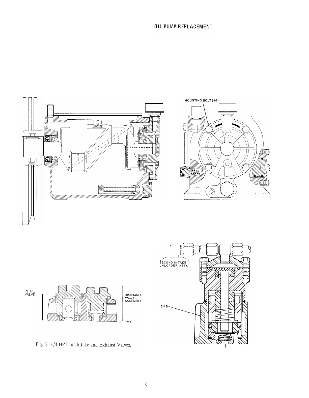
If the source of the trouble has still not been located,
remove and inspect intake and exhaust valves for dirt or
warpage. (NOTE: The head must be removed on the 1/2
HP unit to service valves as they are not removable.) The
piston top and cylinder walls can be inspected at this
time.
PUMP SLOWS, STALLS, OR GOES OUT ON OVER-
LOAD
This is probably the result of the pump seizing. Check
oil level (and pressure in 1 HP and
up).
Check tank pres-
sure, should be 90 psi or lower. (On
WP240
units, turn
off power to both motor-pump units.)
Remove belt and bleed down tank. Turn pump by
hand, it should turn freely. If it does, motor may be
defective. If it does not, it may be the pump or a
plugged aftercooler tube. Disconnect discharge tube and
turn pump by hand again. If still hard turning, problem
is internal to the pump. If it now turns freely, check
piping to tank for obstructions.
EXCESSIVE VIBRATION
Usually due to omission of vibration pads or an
uneven weight distribution on the pads. Check this by
shutting off unit and applying your weight to the dif-
ferent corners of the unit. Excessive rocking should be
shimmed out. In very uneven floors, adjustable levelers
may be needed.
Belt guards often produce a vibrating noise even
under normal operating conditions. Readjusting will
usually eliminate this.
In some cases, the normal operation of the com-
pressor is considered excessive noise or vibration. In
these cases a remote air intake, adjustable pads, and air
line vibration isolators may be required, Isolators are
stocked in the commercial warehouse.
PUMP REMOVAL AND REPLACEMENT
Shut off power, drain oil, and bleed down tank.
Remove belt guard, loosen motor mounts and remove
belt(s).
Remove aftercooler tube at pump end. If tube is type
which wraps around crankshaft, then remove both ends
and any hold down straps.
If flywheel is accessible, then remove at this time;
otherwise it can be removed afterward if necessary. The
1/2 HP unit is held on with a keyed shaft and setscrew
and will probably need a puller. All others use a split
hub and key and can be removed by removing hub bolts
and nuts and driving a wedge into split.
Remove pump intake filter and the unloader air
supply line
(3/4
HP and up). Remove pump hold down
bolts and remove pump. (CAUTION: If flywheel has not
7
75-7131

been removed, its weight may topple pump when the
hold down bolts are removed.)
When installing new pump, be sure flywheel is in line
with motor pulley before removing wedges and tightening.
NOTE: When removing discharge tube connector from
old pump, it is recommended that the male
coupling on the discharge tube be loosely
installed in the connection to prevent its
collapse during removal.
The oil pump is factory ground as an assembly, and
partial replacement is not possible. In the event that the
pump, or crank bearing which is part of the pump, is
deemed faulty, it should be replaced as a unit. The
assembly is held by four bolts (see Fig. 4, front view).
The replacement does not include an oil gauge. If needed,
it must be ordered separately. After reinstallation, the
oil pressure must be adjusted.
K?VKEE
ASSEMBLY
SlDE VIEW FRONT VIEW
3425
Fig, 4. Crankcase and Oil Pump.
t
INTAKE VALVE ASSY.
WP230
Fig. 6. Air Unloading of Intake Valves on 1HP Units.
75-7131

7483X
AIR UNLOADER
ASSEMBLY
-HEAD
WP230-n
Fig. 7. Air Unloading of Intake Valves on 3/4
HP
Units.
Disconnect power and loosen motor clamping bolts
and slide motor towards unit. If the compressor has a
totally enclosed belt guard, it will have to be removed.
Remove and replace belts. Motor should be held snug
against belts when retightening so that the belt(s) do not
have more than 1/2 inch (12 mm) total play. Make
certain alignment is correct, reinstall guard and turn on
power.
NOTE: Sometimes new belts stretch excessively after
being installed; recheck after one week. See
Data Table.
If motor is considered Af fective, disconnect power
and replace motor. When installing motor, reset belt
tension.
Many motors are dual voltage. Check motor
internal wiring against diagrams on motor or inside
of wiring cover plate for proper connections for
voltage being used.
II
INTAKE AND EXHAUST VALVES, UNLOADER
The intake valves, exhaust valves, and unloader
mechanisms can be disassembled for inspection, clean-
ing, or repair in all sizes except the 1/2 HP, The 1/2 HP
unit is a sealed assembly in the head. In the event the
valves are deemed defective in this unit, replace the head
assembly
(Quincy
Part No. 2400-X2P).
On the 1/4 HP unit, remove the two valve locking
nuts in the head and the valve parts can now be removed
for inspection. See Figure 5 for proper order of re-
assembly. The 1/4 and 1/2 HP units have check valve on
the pressure switch and an unloader.
The
3/4
HP unit and larger units have automatic
unloaders on intake valve(s). The unloader for the 1 HP
unit is shown in Figure 6. All other units
(3/4
HP and
up) use the unloader shown in Figure 7. Access to the
intake valves is gained by unscrewing the unloaders from
the head assembly. Exhaust valves can be removed by
unscrewing the hold down caps covering them. See the
Parts List for the replacement numbers for these units.
Fig. 8, Three-Way Valve Assembly (3/4 HP).
Fig. 9. Hydraulic Unloader Assembly.
9
75-7131

The unloader pilot is located on the crankcase and is
connected to the unloader by a copper line. The
3/4
HP
unit uses a pilot that is mechanically activated. All
others are operated by oil pressure (Fig. 9). The units
should be disassembled and cleaned if they are suspect.
See Parts List for repair kits, if required.
PRV STATION
Some 1/4 to 2 HP units use a Honeywell PP902
PRV. For detailed maintenance and repair information,
see Honeywell Sheet No. 75-2558.
The PRV station used on 3 HP units is a combination
of Pall-Trinity-Micro Corp. filter and Norgren regulator
and relief valve.
To perform any maintenance and repair work on the
PRV station, first shut off air supply from tank. Then,
bleed down system by manually operating the drain
(push red button on drain valve). Note that all valves
and dampers will return to their normal position.
The regulator and relief valve can now be removed
and replaced or repaired in place with the appropriate
repair kit (see Parts
List).
After repairing or replacing, slowly turn air back on
checking for leaks.
PARTS LIST
INTAKE FILTERS QUINCY AIR MAZE INTAKE FILTER
1/4 TO 2 HP
INTAKE FILTER
STANDARD OUTDOOR
5318
Quincy
Part Numbers
"5
HP No. 4363HX
QUINCY # 8839 WITH 8914 ADAPTER
5319
Fig. 10.
75-7131
Fig.
11.
10

INTAKE, EXHAUST VALVES AND UNLOADER
ASSEMBLY
DISCHARGE
VALVE
ASSEMBLY
’QUINCY
#2137
X
HEAD ASM QUINCY
#2100-X13P
Fig, 12.
WP230A,
WP240A
Intake and Exhaust Valves,
1/4
HP Units,
INTAKE ASSEMBLY DISCHARGE ASSEMBLY WP230
Fig. 13.
WP230B
Intake and Exhaust Valves on 1/2 HP
Units, (Sold only as Assembly-Quincy Part No.
2400-X2P.)
INTAKE ASSEMBLY DISCHARGE ASSEMBLY
5317
Fig. 14.
WP240B
Intake and Exhaust Valves, 1/2 HP
Unit.
UNLOADER
hYiBkF
(EXCEPT I HP)
QUINCY PT.
#7483X
INTAKE VALVE A
SSY. EXHAUST VALVE
ASSY.
1945 (3/4 &1-1/2 HP) (3/4
&
1-1/2
H P)
QUINCY
# 4610X
QUINCY # 1919 X
Fig. 15.
WP230
Unloader Assembly, 3/4 HP Units and
Up.
INTAKE VALVE ASSY. EXHAUST VALVE ASSY.
1979 (3/4 AND I-l/2 HP) (3/4 AND l-l/2 HP)
QUINCY PT.#
6540X
QUINCY PT.# 8133
Fig. 16.
WP240
Unloader Assembly, 1HP.
Fig. 17. Mechanical Unloader Pilot, 3/4 HP Unit Only.
Repair Kit: Quincy No. 3444,
Fig. 18. Hydraulic Unloader Assembly, Repair Kit:
Quincy No. 8063 (1, 2 and 3 HP Units), Quincy
No. 7697 (1/2 and 5 HP Units).
11
75-7131

UNLOADER
ASSEMBLY
3/4-2
HP
(EXCEPT I HP)
QUINCY PT
#
7483 x
INTAKE ASSEMBLY
QUINCY
PT.
#7277XU DISCHARGE ASSEMBLY
QUINCY PT #7271X WP230
UNLOADER
ASSEMBLY
3/4-20 HP
(EXCEPT IHP)
QUINCY PT
# 7483 X
INTAKE ASSEMBLY DISCHARGE ASSEMBLY WP230
QUINCY PT
#
6671XU QUINCY PT # 6670X
Fig. 19. WP230F, G;
bly, 2 and 3 HP Units. Fig. 20.
WP230H-M
(5 to 20
and 3 HP) Head Assembly.
240F and G(2
Typical
PTM
(Pall-Trinity-Micro)
Filter-PRV
Arrange-
ment--0n 3 HP and Larger Units (
Filter-PRV Station (For
1/4
to 2 HP
well Stations, See Form No. 75-2558)
BY CUSTOMER
TOP VIEW
WALL OUNTED
FRONT VIEW
Fig. 21.
all Mounted.
ELEMENT
SIDE
VIEW
75-7131

FRONT VIEW
Fig. 22. Tank Mounted.
3-20 HP Filter
-
PRV Parts List (Fig. 22)
e
MCC1001SU160Y
6 1Valve
l---f-b
6154
+-/
6155 I 4
9 1Cage, 160 psi
~~305917-00106
,q
5
-
10
Bracket, Tank 8350 8351 8352
- -
4
Notes:
1
-
Order from PTM
2.Order from Norgren
3
-
Obtain Locally
4
-
Order from
Quincy
5
-
Order from Honeywell
13 75-713 1

ORDERING INFORMATION (In United States)
When ordering parts, provide all information on
the name plate and detailed description of necessary
part.
Quincy Parts:
Order from local Quincy representative or:
Colt Industries
Quincy Compressor Division
Quincy, IL 62301
NOTE: State complete Quincy compressor number as
stamped on the nameplate of each compressor
when ordering parts or discussing servicing or
problems on a specific compressor. A list of
service depots is included with the instructions
packed with each compressor,
Honeywell Parts:
Local Honeywell office or:
Honeywell Inc.
1500 W.
Dundee
Road
Arlington Heights, IL 60004
State part number and
compressor
model
number.
WP240 WIRING DIAGRAMS
The two most common ways the
WP240
Air Com-
pressor can be used are:
1. Manual selection of first stage pump unit
with automatic second stage backup. See
Figures 10 and 11.
/Honeywell
MODEL [
WP250
Colt
Industries
Quincy
Compressor
Division Quincy, Illinois us A
ERlAL
DATE CODE
1-1
J
75-7131-d
Fig. 23.
PTM (Pall-Trinity-Micro) Parts:
Local distributor or:
Pall-Trinity-Micro Corporation
Cortland, NY 13045
State exact part number.
Norgren Parts:
Local distributor or:
*
SET P.S.2
5-10
PSI
(35-70kPa)
BELOW P.S.1
C.A.Norgren Company
Littletown, CO 80120
State exact part number,
2. Automatic alternations between pumps after
each pump cycle with automatic backup.
See Figures 12, 13 and 14.
208V
SINGLE PHASE POWER SUPPLY
-
COMP
#2
5320
Fig. 24. Manual Alternation Unit with Automatic Back=
up for Single Phase Units Only. Quincy Wiring
Package WP 1600.
75-7131
14

FUSES, FUSED DISCONNECT OR CIRCUIT BREAKER
li
IF SPECIFIED
t---------i
I
M2
r
110V
H
*
SET P.S.
2 5-10 PSI
(35-70
kPa) BELOW I
P.S.
1
1
‘I
COMP
#2
5322
5324
Fig. 25. Automatic Alternation with Automatic Back-
up. Quincy Wiring Package No. WP1501A.
FUSES, FUSED DISCONNECT OR CIRCUIT BREAKER
li
IF SPECIFIED 1
-A?+~-----
13,
L2
+&-----_.
L2
-
--
4
Ll
L
2
LI
--4 ----_
i
:~
3
Ml COMP
#I
5321
*SET
P.S.
2 5-10 PSI BELOW
P.
S.
1
5323
Fig. 26. Manual Alternation with Automatic Backup for Fig. 28. Automatic Alternation with Backup and Isolated
Three-Phase Units. Quincy Wiring Package No. Control. Quincy Wiring Package No.
1485A.
WP1582. 120 Volt Control Only.
Fig. 27. Automatic Alternation with Automatic Backup
for Single Phase Units Only.
60 HZ
-
ALTERNATOR
[
+.v 120 VAC, 10 AMP BRANCH
CIRCUIT FOR AUX. EQUIPT.
POWER SUPPLY
COMP #I
r---
--+.+--~~-7
15
75-7131

WP25
Refrigeration compressor motor has built-in thermal
and current overload protection but circuit should be
fused. To confirm that the drier is powered and operating,
observe the condensor fan either through the condensor
or from the rear. To confirm that the refrigeration com-
pressor is actually running, on models prior to Sept. 1974,
you will have to reach in from the rear and feel the
hermetic. On larger models you should feel a slight
vibration as well as warmth. A green light indicates proper
cooling. The light is wired to a thermal switch in the unit.
Drier must be wired to run continuously when the
compressor
is
in service and
should not cycle
on
If discharge outlet is not cold, but unit is properly
wired and running, the drier may have lost its refrigerant
charge. If not running, check electrical circuit to be sure
the unit is receiving the correct power supply (see name
plate).
Feel condensate discharge outlet ahead of trap and as
close to drier as possible. The outlet should be cool to
the touch, about 40 to 45 F, under all operational con-
ditions (no flow to full capacity flow of compressed air).
If drier has not been running, energize drier and check
for gradual decrease in temperature at condensate outlet.
Conduction of cold through metal will take about 15
minutes, under no flow condition, to reach 40 to 45 F
(4 to 7
C).
If moisture is detected downstream of the drier,
although drier discharge outlet is cold and trap is working
properly, drier may be operated at too low a pressure or
overloaded by excessive air flow (1-1/2 to 2 HP units
only). Check the compressor tank pressure and percent-
age of operation, The 1-1/2 HP should not be running
over 75 percent or the 2 HP not over 50 percent.
A burned out refrigeration drier unit can be replaced
with a new unit, or a refrigeration service man may find
and repair leaks and re-charge the unit if there is refrig-
erant loss.
75-7131

DATA TABLE SPECIFICATIONS FOR WP230A-M TANK MOUNTED AIR COMPRESSORS FOR HONEYWELL INC.
Tank Size
.
Gallons (Liters)
20 (76)
20(76) 30(114) 30(114) 60(228) 60(228) 60(228)
1
80(304) 120(456) 120(456) 120(456) 120(456)
Cut In Pressure psi (kPa)
Cut Out Pressure psi (kPa)
70 (480) 70(480) 70 (480) 70(480) 70(480) 70(480) 70(480) 70(480) 60(415) 60(415) 60(415) 60(415)
90 (620) 90(620) 90(620) 90 (620) 90(620) 90(620) 90 (620) 90(620) 100 (690)
100 (690) 100 (690)
1
100 (690)
Inlet Size NPT (Compr)
1/4
(6) l/2
(13) 3/4
(19)
l/2 (13)
3/4
(19)
l-l/4(31)
l-1/4
(31)
2
(50) 2
(50)
2
(50)
--
--.I
Note: Part Numbers listed are
Quincy
numbers.
aOrder
Replacement Elements from Honeywell Local Business Office
bO
to 60 psi (0 to 415
kPa)
on 7-l/2 to 20 HP Units
c60
to 100 psi (415 to 690
kPa)
on 7-l/2 to 20 HP Units

DATA SPECIFICATIONS FOR WP240 DUPLEX AIR COMPRESSORS
a
Honeywell No.
WP24OA WP240B WP24OC WP240D WP24OE WP240F WP240G
Quincy
Model No. FFHX2 FFHlO6 FFHlO8 FFH210 FFH216 FFH230 FFH240
aEach
WP240 model has two identical motor-pump units. Data specified is applicable to both units.
bUnIoader solenoid in aftercooler line.
cOrder Replacement Elements from Honeywell Local Branch Office.


SALES AND
SERVICE
-
ALABAMA GEORGIA
Birmingham, AL Atlanta, GA
(205) 323-2431 (404) 321-2495
MARYLAND NEW YORK
Baltimore, MD Albany, NY
(301) 828-0900 x247 (518) 456-7000
PENNSYLVANIA
Harrisburg, PA
(717) 564-8000
VIRGINIA
McLean (Washington D .C.), VA
(703) 827-3705
Richmond, VA
(804) 285 8211 or
1-800-522-3807 (Toll Free)
Mobile, AL
(205) 479-8572 HAWAII
Honolulu, HI
(808) 537-5514
IDAHO
Boise, ID
(208) 375-1618
ILLINOIS
Chicago North (Lincolnwood), IL
(312) 674-9770 x 354
MASSACHUSETTS
Boston (Newton), MA
(617) 969-0250
Buffalo, NY
(716) 835-2770 Philadelphia (Valley Forge), PA
(215) 666-8302
Long Island, NY Pittsburgh, PA
(212) 392-4300 (412) 928-4236
Plainview, NY
(516) 931-1500 Wilkes Barre, PA
(717) 654-2477
Rochester, NY
(716) 424-2700 RHODE ISLAND
Providence, RI
(401) 438-6000
ALASKA
Anchorage, AK
(907) 274-0551
ARIZONA
Phoenix, AZ
(602) 249-7155
Roanoke, VA
(703) 989-5201
MICHIGAN
Detroit (Farmington Hills), MI
(313) 478-1600
Grand Rapids, MI
(616) 247-4811
Saginaw, Ml
(517) 792-8707
Virginia Beach (Norfolk), VA
(804) 461-0265
Tuscon, AZ
(602) 795-4209 WASHINGTON
Seattle, WA
(206) 233-2030
Chicago South (Lansing), IL
(312) 568-4200 Syracuse, NY
(315) 451-4000
ARKANSAS
Little Rock, AR
(501) 372-0166
SOUTH CAROLINA
Columbia, SC
(803) 288-1825 or
(803) 779-3240
Elgin, IL
(312) 697-7880 MINNESOTA
Minneapolis (Edina), MN White Plaines, NY
(914) 948-7511 Spokane, WA
(509) 328-4250
(612) 830-3880 NORTH CAROLINA
CALIFORNIA
Irvine, CA
(714) 557-6431
Los Angeles, CA
(213) 726-6161
Sacramento, CA
(916) 485-0581
Lansing, IL
(312) 474-9300
Peoria, IL
(309) 692-0610 X 220
INDIANA
Fort Wayne, IN
(219) 492-9654
Duluth, MN
(218) 727-0401
Charlotte, NC
(704) 364-4770 Greenville, SC
(803) 288-7825 WEST VIRGINIA
Charleston, WV
(513) 948-4185
MlSSlSSlPPl Greensboro, NC
(919) 292-1556
SOUTH DAKOTA
Sioux Falls, SD
(605) 336-0986 Clarksburg, WV
(304) 623-6551
Jackson, MS
(601) 982-20900 or NORTH DAKOTA
(601) 833 7241 Fargo, ND
(701) 235-4221 TENNESSEE
Memphis, TN
(901) 345-6222
WISCONSIN
Appleton, WI
(414) 733-4491
Madison, WI
(608) 222-3400
Milwaukee, WI
(414) 771-6300
San Diego, CA
(714) 292-5311 IIndianapolis, IN
(317) 243-0831
X 281 or 248
MISSOURI
Kansas City, MO
(816) 358-4200
OHIO
Akron, OH
(216) 733-2244
San Francisco, CA
(415) 957-2674
Nashville, TN
(615) 385-3400 or
1-800-342-2314 (Toll Free)
St Louis, MO
(314) 576-2566 Canton, OH
(216) 454-6960
IOWA
Bettendorf, IA
3705 Utica Ridge Rd
Davenport, IA
(319) 359-3441
Des Moines, IA
(515) 288-3601
KANSAS
Witchita, KA
(316) 522-3431
KENTUCKY
Louisville, KY
(502) 459-5970
LOUISIANA
Baton Rouge, LA
(504) 924-8626
COLORADO
Denver (Engelwood), CO
(303) 779-6295 or
1-800-332-7031 (Toll Free)
CONNECTICUT
Hartford, CT
(203) 762-3100
DISTRICT OF COLUMBIA
Washington D.C. (McLean, VA)
(703) 827-3705
FLORIDA
Jacksonville, FL
(904) 396-6971
MONTANA
Missoula, MT
(406) 728-7442
Cincinnati, OH
(513) 948-4185
Cleveland, OH
(216) 361-7373 Dallas, TX
TEXAS
Austin, TX
(512) 478-1788 WYOMING
Casper, WY
(307) 265-9374 or
1-800-443-8446 (Toll Free)
NEBRASKA
Omaha, NB
(402) 331-3200
Columbus, OH (214) 387-5416
(614) 486-5971 X210 El Paso, TX
(915) 533-9924
NEW HAMPSHIRE Dayton, OH
Bedford, NH (513) 237-4035
(603) 625-6502 Ft Worth, TX
(214) 263-2311
Toledo, OH
NEW JERSEY (419) 473-972, X214
Mt Laurel, NJ
(609) 234-2224 Youngstown, OH
(216) 747-0072
Houston, TX
(713) 780-6603 or
1-800-392-2328 (Toll Free)
Lubbock, TX
(806) 762-5202
Miami, FL
(305) 592-8140 Parsippany, NJ
(201) 263-2225 OREGON
Portland, OR
(503) 235-8411
New Orleans, LA
(504) 833-7241
Orlando, FL
(305) 894-3131 Westfield, NJ
(201) 233-9200 OKLAHOMA
Oklahoma City, OK
San Antonio, TX
(512) 341-4691
Schreveport, LA
(318) 222-5325
MAINE
Portland, ME
Tampa, FL
(813) 870-3733 (405) 848-2811
NEW MEXICO
Albuquerque, NM Tulsa, OK UTAH
Salt Lake City, UT
West Palm Beach, FL
(305) 683 1990 (207) 775-3501 (505) 345-1656 (918) 437 5934 (801) 487-0681
CANADA
— Honeywell Limited – Honeywell Limiteé, 740 Ellesmere Road – Scarborough, Ont.
ALBERTA
Calgary
Edmonton
MANITOBA
Winnipeg ONTARIO
Hamilton
London
Ottawa
Sudbury
Toronto
Windsor
QUEBEC
Montreal
Quebec
SASKATCHEWAN
Regina
Saskatoon
NEWFOUNDLAND
St. John 's
BRlTlSH COLUMBIA
Vancouver NEW BRUNSWICK
Moncton NOVA SCOTIA
Halifax
INTERNATIONAL
-Hannover-Langenhagen
Mannheim
Munich
Nurnberg
Stuttgart
Kokura
Nagasaki
Nagoya
Nihama
Ft. Washington, Pa (USA)
Los Angeles, Calif. (USA)
Oita
Okayama
Osaka
Sapporo
Tokuyama
Tomakomai
Toyama
Yokkaichi
NEW ZEALAND †
AUCKLAND
Christchurch
Dunedin
Wellington
SWEDEN
STOCKHOLM
Goteborg
Malmo
Sundsvall
SWITZERLAND
ZURICH
Basel
Bern
Geneva
TAIWAN t
TAIPEI
UNITED KINGDOM
LONDON Bracknell
Belfast
Birmingham
Cardiff
Cheadle Hulme
Dublin (Rep Ireland)
East Kilbride (Scotland)
Maidenhead
Middlesbrough
Motherwell
Sheffield
VENEZUELA
CARACAS
Maracaibo
Valencia
SUBSIDIARIES AND AFFILIATES†
ARGENTINA
BUENOS AIRES
AUSTRALIA
WATERLOO, N.S.W.
Adelaide
Canberra
Darwin
Hobart
Melbourne
Perth
Queensland
Townsville
Wollongong
AUSTRIA
VIENNA
Graz
Innsbruck
Klagenfurt
Linz
BRAZIL
SAO PAULO
Rio de Janeiro
DENMARK
COPENHAGEN
Aarhus
FINLAND
ESPOO
Kuopio
Tampere
FRANCE
BOIS D’ARCY
Bordeaux
Lille
Lyon
Marseilles
Nantes
Strasbourg
HONG KONG NORWAY
BERGEN
Sandvika
Stavanger
Tromso
Trondheim
PUERTO RICO
San Juan
IRAN
TEHERAN
ITALY
MILAN
Bologna
Firenze KUWAIT
Padova
Rome
Torino
SINGAPORE †
GREECE
Athens
SOUTH AFRICA
JOHANNESBURG
Capetown
Durban
Port Elizabeth
Pretoria
JAPAN †
TOKYO
Chiba
Fukuoka
Fukuyama
Himeji
Hiroshima
Kashima
Kitakyushu
MEXICO
MEXICO CITY D.F.
Monterrey
BELGIUM
BRUSSELS
Gent
Liege/Grivegnee
Luxembourg
GERMANY
OFFENBACH/MAIN
Berlin
Bonn
Dusseldorf
Hamburg
SPAIN
MADRID
Barcelona
Gijon
NETHERLANDS
AMSTERDAM
Schiphol Centrum
HONEYWELL•Minneapolis,
Minnesota
55408•Scarborough,
Ontario•Subsidiaries
and Affiliates Around the World.•Printed in U.S.A.
This manual suits for next models
2
Table of contents
Other Honeywell Air Compressor manuals
Popular Air Compressor manuals by other brands

Sears
Sears Craftsman 919.167312 owner's manual

Coleman
Coleman Air Compressors Operator's manual

Iwata
Iwata Power Jet Series user manual

Black & Decker
Black & Decker BD 160/24 instruction manual

Sullivan-Palatek
Sullivan-Palatek D210PHKR Operation & service manual

L&W Compressors
L&W Compressors LW 320 B MC owner's manual

Porter-Cable
Porter-Cable CPF23400P instruction manual

AEROTECNICA COLTRI
AEROTECNICA COLTRI MCH-3/EM CNG Use and maintenance manual

Graco
Graco 24U176 Instructions - parts

DeVilbiss
DeVilbiss FA125-1 owner's manual

Sullair
Sullair LS-25S-257KW Operator's manual and parts list

EINHELL
EINHELL TC-AC 240/50/10/2 OF Original operating instructions