Honeywell BGGIN0070 Parts list manual

1
IMPORTANT INSTRUCTIONS
AND OPERATING MANUAL
Thank you for purchasing this product! If you have questions about the product such as
missing parts,damaged products,product assembling and operation etc.,please contact us
Via Amazon Message.
.
LP GAS GRILL
For both SKU BGGIN0070 and SKU BGGIN0071
Model: BGGIN0070 Model: BGGIN0071

2
TABLE OF CONTENTS
Safety Information ...................................................................................................................... 3
Package Contents ...................................................................................................................... 5
Hardware Contents .................................................................................................................... 5
Preparation ................................................................................................................................. 6
Assembly Instructions ................................................................................................................ 6
Operation Instructions ................................................................................................................. 13
Care and Maintenance ................................................................................................................. 17
Troubleshooting ........................................................................................................................... 20
Assembler/Installer:
This manual contains important information that is necessary for the proper
assembly and safe use of this appliance. Read and follow all warnings and instructions before
assembling and using this appliance.
Leave these instructions with the consumer .
Consumer/User: Follow all warnings and instructions when using this appliance.
Retain these instructions for future reference.
If you smell gas:
1. Cut off gas to the appliance.
3. Open lid.
4. If odor continues, keep
away from the appliance and
department.
1. Do not store or use gasoline
vapors colse to this or any other
appliance.
2. An LP (liquid propane) cylin-
der not connected for use shall
not be stored colse to this or
any other appliance.
3. This grill is only for outdoor
using and shall not be used in
a building, garage, under
overhangs or any other
enclosed area.
4. Do not leave a lit grill unat-
tended. Keep children and pets
away from the grill at all times.
WARNING
DANGER

3
mbustion of such fuels contain
chemicals, including Benzene, known to the State of California to cause cancer, birth defects or
other reproductive harm. This product contains chemicals, including lead and lead compounds,
known to the State of California to cause cancer, birth defects or other reproductive harm. Wash
hands after handling.
CALIFORNIA PROPOSITION 65
DANGER
• Do not use in an explosive atmosphere. Keep grill area clear and free from combustible
SAFETY INFORMATION
CAUTION
• Do not use gasoline, kerosene or alcohol for lighting.
• The LP gas cylinder used with this appliance must be:
of the U.S. Department of Transportation (D.O.T.) or the National Standard of Canada,
CAN/CSA-B339, Cylinders, Spheres and Tubes for Transportation of Dangerous Goods;
and Commission, as applicable; and
(c) Provided with a cylinder connection device compatible with the connector for outdoor
cooking appliances. This grill is not intended to be used in or installed on recreational
vehicles and/or boats.
•
increase, may open the relief valve and leak the gas.
• Always open grill lid slowly and carefully as heat and steam trapped within the grill can hurt
you severely.
Thank you for purchasing this product! If you have questions about the product such as
missing parts,damaged products,product assembling and operation etc.,please contact us
Via Amazon Message.

4
SAFETY INFORMATION
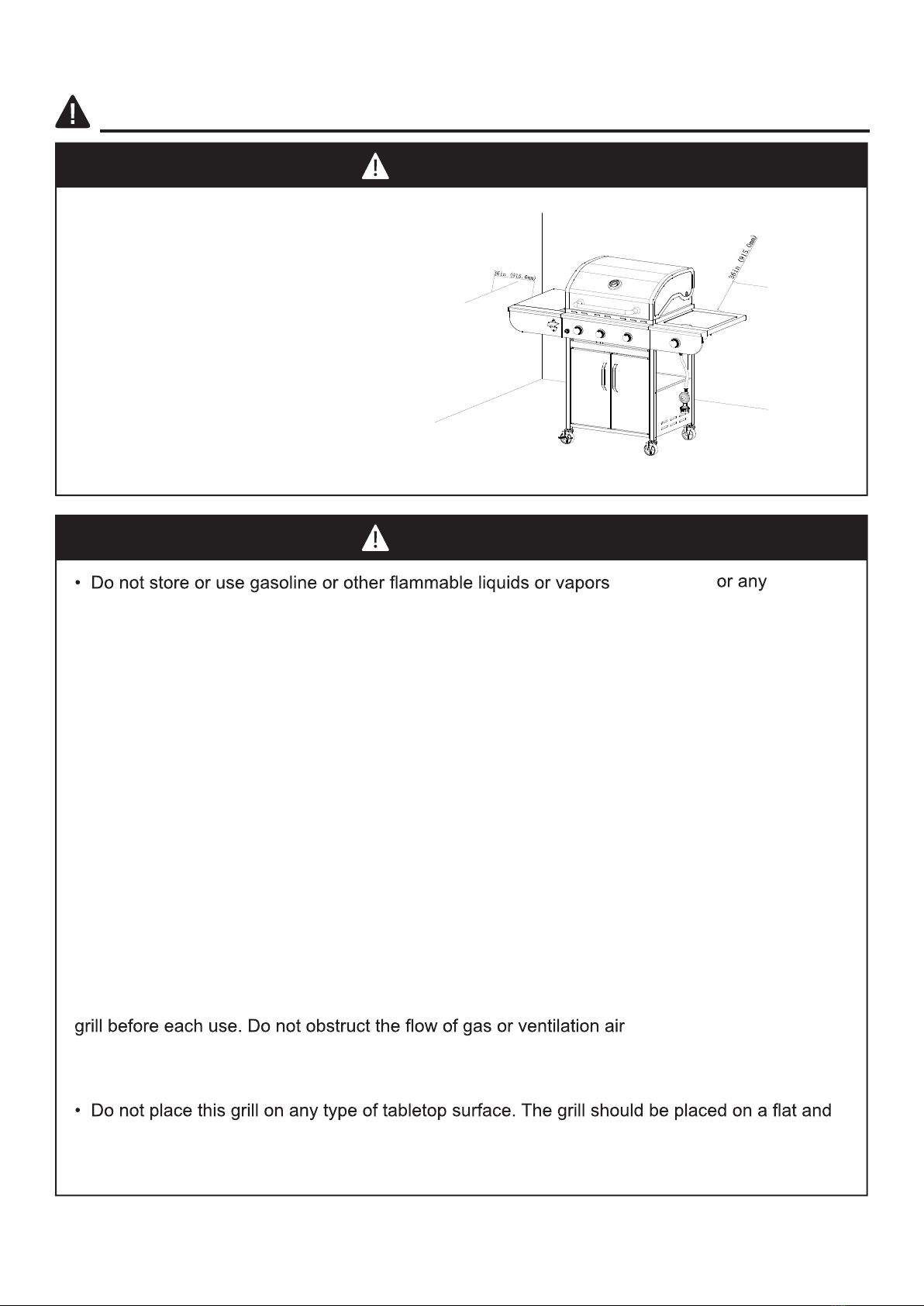
• Do not place the grill under overhead
combustible construction or awnings.
Minimum clearance from sides and
back of unit to combustible construction,
36 inches (915.0mm) from sides and
back.
NOTE: The installation must conform with
local codes or, in the absence of local
codes, with either the National Fuel Gas
Code, ANSI Z223.1/NFPA 54, Natural
Gas and Propane Installation Code, CSA
B149.1, or Propane Storage and
Handling Code, B149.2.
WARNING
CAUTION
other appliance.
• An LP cylinder not connected for use shall not be stored close to this or any other
appliance.
• This grill is for using with propane gas only (proane cylinder not included).
• Never attempt to attach this grill to the self-contained propane system of a boat, camper trailer,
motor home or house.
• Do not attempt to move the grill while it is lit or when it is hot. The casters should be locked
down when not moving the grill.
• Do not use the grill unless it is completely assembled and all parts are securely fastened and
tightened.
• Keep all combustible items and surfaces at least 36 inches (91.50 cm) away from the grill at all
times.
• Do not touch metal parts of grill until it has completely cooled (about 45 minutes) to avoid
burns, unless you are wearing protective gear (pot holders, gloves, BBQ mittens, etc…).
• Do not alter this grill in any manner.
• Clean and inspect the hose before each use. If there is obvious abrasion, wear, cuts, or
leaks, the hose must be replaced prior to operating the appliance. The replacement hose
• Move gas hoses as far away as possible from the hot surfaces and dripping hot grease.
• Keep the grill’s valve compartment, burners and circulating air passages clean. Inspect the
.
• The use of alcohol, prescription or non-prescription drugs may influence the operator’s ability
to properly assemble or safely operate the grill.
•Do not leave a lit grill unattended. Keep children and pets away from the grill at all times.
level surface.
• Do not use the grill in huge winds.
close to this
shall be in accordance with supplier’s standard.

PACKAGE CONTENTS
5
BGGIN0070 BGGIN0071 BGGIN0071
BGGIN0070

Assemble the bottom plate (10) and Cart frame (8) to left cart assembly (6) ,
Right cart assembly (11) usingM6x12mm bolts (AA)。
Assemble the locking caster (12) to the left cart asse mbly (6) ,Attach the
non-locking caster (14) to the right cart assembly (11) using wrench (KK)。
6
ASSEMBLY INSTRUCTIONS
1
PREPARATION
Beforebeginningassemblyofproduct,makesureallpartsarepresent.Comparepartswithpackage
contentslistonpreviouspageandhardwarecontentsabove.Ifanypartismissingordamaged,do
notattempttoassembletheproduct.Contactcustomerserviceforreplacementparts.
Estimated AssemblyTime:50minuteswith2people.
ToolsRequiredfor AssemblyandLeakTesting(notincluded):Phillipsscrewdriver, Spraybottle,
Pliers, AdjustableWrench
CAUTION
THIS UNIT IS HEAVY. Two people required for
safe assembly.
Two people required for safe assembly
. Some parts may contain sharp edges.
Wear protective
gloves if necessary. Read and follow all safety statements, warnings, assembly instructions and
use and care instructions before attempting to assemble and use.

FirstassembletheDoorpost(CC)tothe Bottomplate,Thenassemblemagnetbase(13)
totheBottomplateusingM5x10mm bolts(BB)
。
7
ASSEMBLY INSTRUCTIONS
3
4First assemble the Handle (4) and match holder (26) to the right door (15) using M4x5mm
bolts (EE) and washer (FF) ,
Then assemble the right door to the Bottom plate (10) and cart
frame (8) using door axle (DD)
。
Install the left door as above
Assemble the back panel (9) to the left cart assembly(6) and right cart assembly (11)
2
using M6x12mm bolts (AA)

8
6
7First Assemble the Bottle opener (7) to the left front panel (3) using M4x10mm bolts(JJ)
assemble the M6x12mm to the the left front panel and intstalled one piece of (BB) on the left
5Assemble the lid handle (28) and The Handle base (29) using M6x12mm bolts(AA) to the lid.
Assemble the Thermometer (27) to the lid. First remove the stronger (no need install back),
FirstAssemble the M6x12mm tothebody ,Reservedistance of5mm,matchscrewholeson
the(2) to(AA) whichhavebeeninstalledtohang(2) onthescrews,don’t tightenthescrews.
Then openthecoverandinstalledanothertwo(AA) insideofthe(1).Afterthat,tightenall(AA).
of the body.Reserve a distance of 5mm,Then match the screw holes on the (3)left front panel
to (BB) and (AA)which have been installed. Hang(3)left front panel on the installed screws,
don't tignten the screws. Then open the cover and intstalled another one (BB)inside of the body.
After that, tighten al screws.
Assemble the Lid & body assembly (1) to the cart left &right cart assembly using M6x35 mm
bolts (HH) and M6 nuts (II)
Attention:Stronger is for protection of the part (1) during transportation,no need to install back
after remove.
ASSEMBLE INSTURSTIONS

9
ASSEMBLY INSTRUCTIONS
FirstAssembletheM6x12mmbolts(AA)tothebody,Reserveadistanceof5mm。Thenfix
thesideburnertable(20)tothebodyusingM6x12mmbolts(AA)
8
9
FirstAssembletheM6x12mmbolt(AA)totherightfrontpanel(21),Keepadistanceof5mm
Thenassembletherigthfrontpanel(21)tothecontrolpanelandsideburnertableusingM5x10
mmbolts(BB)
FirstAligntothesidevalveandsideburner(24)thenassembleittothesideburnertableusing
M4x8mmbolt(GG)。
10Assemble the side valve and knob base (22) tothe right front panel using M4x8mm bolts (GG)
Incorrect
Incorrect
Correct

10
ASSEMBLY INSTRUCTIONS
Assemble the knob (23) to the side valve Assemble the ingition pin to the side burner
table using M4x8mm bolts (GG)
11
12
Remove the ignitor cap,insert AA battery(1.5V) into the ignitor body with the positive “+” end
facing out ,replace ignitor cap.
Assemble the side burner rack(19) to the side burner table.put the warming rack(16) ,cooking
grills(17),flame tamer (18) into the body.
13Attachthegreasebox(25)tothegreasetray
WARNING: IT IS VERY IMPORTANTTO CHECK
AND ENSURETHAT EACHAND EVERY BURNER
IS FULLY ENGAGED WITH THE ADJACENT VALVE
ORIFICE BEFORE COMPLETING STEP 10.
FAILURE TO DO SO MAY RESULT IN FIRE OR
EXPLOSION, POSSIBLY CAUSING SERIOUS
INJURY OR DEATH. REFER TO MAINTENANCE
SECTION INSTRUCTIONS TO PROPERLY CHECK THE
ENGAGEMENT.

ASSEMBLY INSTRUCTIONS
11
Finish
Model:BGGIN0070
Model:BGGIN0071

Open the left door assembly and the right
door assembly , insert the hose/regulator
assembly into the cart assembly through the
clearance above the cart right side panel
assembly . Place LP gas cylinder (sold
separately) into the nesting hole located in the
cart bottom shelf . Rotate the LP gas
cylinder until the hose/regulator coupling aligns
with the threaded valve of the cylinder. Hand-
tighten the hose/regulator coupling to the
threaded valve of the LP gas cylinder.
Tighten the tank screw clockwise in the
rear of the cart until the LP gas cylinder is
secured in place inside the nesting hole of the
cart bottom shelf .
Tank Screw
ASSEMBLY INSTRUCTIONS
LP Gas Cylinder
Tank Screw
Front View
Rear View
12

OPERATION INSTRUCTIONS
CHECKING FOR LEAKS
gs on the LP gas tank valve, gas hose
and regulator for leaks with a water and soap solution.
•Always perform leak test prior to lighting the grill.
•Do not smoke while testing for a leak.
•Always perform leak tests outdoors in a well-ventilated area.
•Do not use the grill until any and all leaks are corrected.
•If you are unable to correct a leak, disconnect the propane supply and call a gas appliance service
dealer.
PERFORM LEAK TEST
•Prepare leak test solution by 50/50 ratio of liquid dish soap and water.
Total solution required is approximately 2 - 3 ounces (70 - 90 ml).
Put leak test solution in a spray bottle.
•Ensure all control knobs are in the OFF position.
•Connect the gas hose to the gas supply.
•Open the LP gas tank valve.
•Spray leak test solution on all gas carrying connections an
of applied test solution indicates a gas leak. If leaks are detected or you smell or hear gas, shut off the
gas supply valve immediately and repair or replace the defective part. Do not use the grill until
all leaks are corrected.
WARNING
ALL INSTRUCTIONS AND SAFEGUARDS ON THIS PAGE MUST BE FOLLOWED TO
PREVENT FIRE, DAMAGE AND/OR INJURY.
CAUTION
Only use the regulator and hose assembly provided! If a replacement is necessary, please call
our customer service center. Do not use replacement parts that are not intended for this grill.
13

OPERATION INSTRUCTIONS
CONNECTING GAS CYLINDER
The propane gas supply cylinder to be used must be constructed and marked in accordance with the
Standard of Canada, CAN/CSA-B339, Cylinders, Spheres and Tubes for Transportation of Dangerous
Goods; and Commission, as applicable; and provided with a liste
Use only 20-pound cylinders (height: 18.11 inches, tank diameter: 9.84 inches, foot diameter: 8.03 inches)
equipped with a cylinder connection device compatible with the connection for outdoor cooking
appliances.
The cylinder must include a collar to protect the cylinder valve. The gas cylinder should not be dropped
or handled roughly!
If the appliance is not in use, the gas cylinder must be disconnected. Storage of an appliance indoors
is permissible ONLY if the cylinder is disconnected and removed from the appliance. Cylinders must
be stored outdoors out of the reach of children and can not be stored in a building, garage or any
other enclosed area. Your cylinder must never be stored where temperatures can reach over 125°F.
Place dust cap on cylinder valve outlet whenever the cylinder is not in use. Only install the type of
dust cap on the cylinder valve outlet that is provided with the cylinder valve. Other types of caps or
plugs may result in leakage of propane.
Before connection, be sure that there is no debris caught in the outlet of the gas cylinder, outlet of the
regulator valve or in the outlet of the burner and burner ports. Connect regulator valve and
the regulator valve when the grill is not in use.
the proper cylinder orientation to provide vapor withdrawal. NOTE: The cylinder must be fully upright
for the cylinder to have vapor withdrawal only.
CAUTION
a. Do not store a spare LP-gas cylinder under or near this appliance.
injury may occur.
14

OPERATION INSTRUCTIONS
NOTE: Other cylinders may be acceptable for use with this appliance If they are compatible with the app-
-liance nesting hole and retention means. Refer to Page11of the Assembly Instructions for corr-
ect cylinder to cylinder holder connection.
WARNING
ALL INSTRUCTIONS AND SAFEGUARDS ON THIS PAGE MUST BE FOLLOWED TO
PREVENT FIRE, DAMAGE AND/OR INJURY.
WARNING
In the connection process, make sure:
•the regulator inlet connector mates with the cylinder valve o
CONNECTING THE LP TANK
1. The knob on the LP tank must be closed. Make sure that the knob is turned clockwise to a
full stop. The cylinder supply system must be arranged for vapor withdrawal.
2. Check that the control knob on the control unit is turned off.
3. Remove the protective cap from the LP tank valve and coupling nut.
4. Hold the regulator in one hand and insert the nipple into the valve
outlet. Be sure the nipple is centered in the valve outlet. The coupling
nut connects to the large outside threads on the valve outlet. Use
care – do not cross thread the connection.
5. Hand-tighten the coupling nut clockwise until it comes to a full
stop. Firmly tighten by hand only. Do not use tools.
To Disconnect: Fully close the tank valve by turning clockwise.
Turn the coupling nut counterclockwise until the regulator assembly detaches.
15

OPERATION INSTRUCTIONS
Lighting The Grill
Remove all hangings or plastic straps, if present. Before you cook on your new gas grill, it is important
to clean your grill with heat. To do this, operate the grill for approximately 15 minutes with the lid closed
and the control knob in the highest position. This will clean the internal parts by burning off any residue
and odor from the manufacturing process.
WARNING
Do not lean over grill when lighting. Read instructions before lighting.
CAUTION
ion, immediately TURN OFF the
cylinder valve and then TURN OFF the control knob.
1. Check that the control knobs are in the OFF position.
2. Open valve at tank fully by turning counterclockwise.
3. Open lid during lighting.
4. Push igniter down 3 to 4 seconds while turning right side control knob to the high position. The
burner should ignite. If ignition does not take place within 5 seconds, immediately turn the control knob
to the OFF position. Wait 5 minutes and repeat step 4 above or refer to match lighting instructions
in the manual.
5. Repeat step 4 above to ignite all other burners.
If the burner still does not light, check that there is gas in the cylinder and follow the match lighting
instructions. Check the Troubleshooting Guide on page 28 for more information.
16

OPERATION INSTRUCTIONS
SHUTDOWN INSTRUCTIONS
1. Turn control knobs clockwise to the OFF position.
2. Close valve at tank fully by turning clockwise.
3. Close lid.
Turn off LP supply at cylinder when appliance is not in use.
CAUTION
Make sure all burners controls are off except for the burner being lit and the
burners that have been lit.
Main Burner Match Lighting
Side Burner Match Lighting
LIGHTING THE GRILL WITH A MATCH
1. Open the lid.
2. Insert a match in the end of the match holder that is installed on the right door assembly.
3. Light the match.
4. Immediately place the lit match through the spaces in the grill gates near the ports of the burner
between the heat tents as shown. Make sure the lit match is close to the burner ports.
5. Press in the control knob that operates the burner and rotate counter-clockwise to High
position and burner should light immediately.
6. Repeat 2–5 steps to light the remaining burners.
7. Adjust burners to desired cooking settings.
17

18
CARE AND MAINTENANCE
Cooking Grates
The best time to ‘burn-off’ the cooking grates is after every use (approx. 15 minutes). The grill is
already hot from cooking thus requiring less fuel to obtain necessary temperature for ‘burn-off’.
To ‘burn off’ or heat clean your grill, turn the burners to highest position and run for 15 minutes
with the lid closed. Then turn off the burners and use a wire brush to clean excess food residue
from the grates.
d should be handled with care
not to chip.
CAUTION
Ensure the grill is cool before cleaning and conducting maintenance and with the gas supply
turned off at the LP-Gas Cylinder.
Recommended Cleaning Supplies
Mild liquid dish soap, warm water, nylon cleaning pad, wire brush
DO NOT use cleaners that contain acid, mineral spirits or any abrasive substance.
Outside Surfaces
It is recommended to use only mild dish soap and hot water to clean grill and grill parts.
Rinse with warm water.
Inside Bottom Pan of Grill Body
Remove residue using a brush, scraper and/or cleaning pad. Wash with mild dish soap and warm
water. Rinse with warm water. Avoid water splashing into venturi tubes of burners.
Heat Tents
Clean residue with wire brush and wash with mild dish soap and
warm water. Rinse with warm water.
Grease Cup
Empty the grease cup and clean with mild dish soap and
warm water on a regular basis.
Checking The Flame
should be a blue-yellow color and be between 1- 2 inches high.

Figure 2
CARE AND MAINTENANCE
Burner Assembly
Removing The Burner Assembly
1. Make sure all control knobs are in the OFF
position, gas supply valve is closed, and the
gas hose is disconnected from the gas supply.
2. Remove the ignitor cap, then remove the
AA battery (1.5V) (K) out of the ignitor body.
Replace ignitor cap.
3. Open lid and remove warming rack, cooking
grates, heat tents, clip for burner, ignition
chain and main burner.
Warming Rack
Cooking
Grates
Heat Tents
4. Remove hinge pin as illustrated in Figure 1.
6. Detach ignition wire from electrode in Figure 2.
Figure 1
19

CARE AND MAINTENANCE
View the correct position
Bottom View Wrong
Wrong
Correct
WARNING
may result, possibly
causing serious bodily injury or death.
Other Care and Maintenance
It is recommended that inspection and service on this appliance
service person.
It is recommended that you always check that the outdoor cooking appliance area is clear and free
nd liquids before lighting.
ustion and ventilation air are not
obstructed.
It is recommended that you regularly check that the ventilation openings of the grill cabinet
are free and clear from debris.
It is recommended that you regularly check and clean the burner/venturi tubes for insects and insect
Cleaning the Burner Assembly
– Make sure the grill is cool
1. Turn gas off at the control knobs and LP gas cylinder.
2. Disconnect LP gas cylinder from regulator and hose.
3. Remove warming rack, cooking grates and heat tents.
4. Detach burner by removing the cotter pins at the back of the burners to detach them from the brackets.
5. Detach ignition wire from electrode by hand only. DO NOT use pliers or any other tool as it may damage
the electrode or wire.
6. Lift burner slowly.
7. Ensure all burner ports are clear of clogs. Use of a pin or paper clip works well.
8. Ensure burner is free of any damage. If damage is found, replace it with new burner.
9. Ensure the end of the burner and primary air screen are clear from insect nests, dirt or debris.
Re-installing the Burner
urner inlet (venturi).
osition.
ox vent holes as illustrated below.
Reattach each burner with the hinge pin and reattach the ignition wire to electrode.
20
This manual suits for next models
1
Table of contents
Other Honeywell Grill manuals
Popular Grill manuals by other brands

Napoleon
Napoleon TravelQ 285X manual

Kenmore
Kenmore 119.16312800 Use & care guide

Bodum
Bodum FYRKAT 11450 Instructions for use

Broil King
Broil King SOVEREIGN 20 Assembly manual & parts list

Linea 2000
Linea 2000 DOMO DO9049BQ Instruction booklet

KitchenAid
KitchenAid 720-0893 Installation Instructions and Use & Care Guide