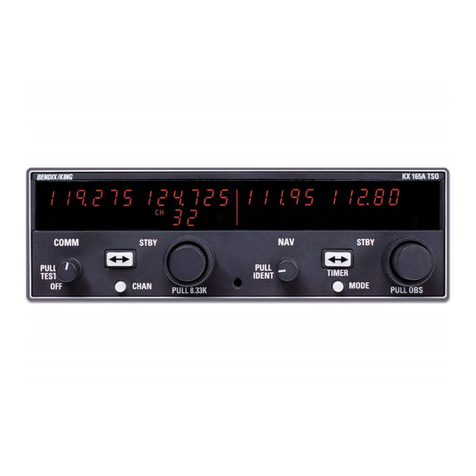
Honeywell Bendix/King KX 165A User manual

MAINTENANCE MANUAL
KX 165A
NAV/COMM TRANSCEIVER
MANUAL NUMBER 006-15610-0000
REVISION 0 JUNE, 2000

WARNING
Prior the export of this document, review for export license requirement is needed.
COPYRIGHT NOTICE
©2000 Honeywell International Inc.
Reproduction of this publication or any portion thereof by any means without the express written
permission of Honeywell is prohibited. For further information contact the manager, Technical
Publications, Honeywell, One Technology Center, 23500 West 105th Street Olathe KS 66061
telephone: (913) 782-0400.

BENDIX/KING KX 165A
Rev 0, Jun/2000 15610M00.RCD Page i
SECTION IV
THEORY OF OPERATION
4.1 GENERAL . . . . . . . . . . . . . . . . . . . . . . . . . . . . . . . . . . . . . . . . . . . . . . . . . . . . . . . . . . . . . 4-1
4.1.1 KX 165A FEATURES. . . . . . . . . . . . . . . . . . . . . . . . . . . . . . . . . . . . . . . . . . . . . . 4-1
4.2 BLOCK DIAGRAM THEORY OF OPERATION . . . . . . . . . . . . . . . . . . . . . . . . . . . . . . . . . 4-2
4.2.1 COM RECEIVER . . . . . . . . . . . . . . . . . . . . . . . . . . . . . . . . . . . . . . . . . . . . . . . . . 4-3
4.2.2 TRANSMITTER . . . . . . . . . . . . . . . . . . . . . . . . . . . . . . . . . . . . . . . . . . . . . . . . . . 4-9
4.2.3 VOR/LOC RECEIVER . . . . . . . . . . . . . . . . . . . . . . . . . . . . . . . . . . . . . . . . . . . . 4-13
4.2.4 GLIDESLOPE RECEIVER . . . . . . . . . . . . . . . . . . . . . . . . . . . . . . . . . . . . . . . . 4-17
4.2.5 CENTRAL PROCESSING UNIT (CPU) . . . . . . . . . . . . . . . . . . . . . . . . . . . . . . 4-21
4.2.6 POWER SUPPLY . . . . . . . . . . . . . . . . . . . . . . . . . . . . . . . . . . . . . . . . . . . . . . . 4-23
4.2.7 FRONT PANEL AND DISPLAY . . . . . . . . . . . . . . . . . . . . . . . . . . . . . . . . . . . . 4-23
4.2.8 VOR/LOC Converter Board . . . . . . . . . . . . . . . . . . . . . . . . . . . . . . . . . . . . . . . 4-27
4.3 DETAILED CIRCUIT THEORY . . . . . . . . . . . . . . . . . . . . . . . . . . . . . . . . . . . . . . . . . . . . 4-29
4.3.1 COM RECEIVER . . . . . . . . . . . . . . . . . . . . . . . . . . . . . . . . . . . . . . . . . . . . . . . . 4-29
4.3.2 TRANSMITTER . . . . . . . . . . . . . . . . . . . . . . . . . . . . . . . . . . . . . . . . . . . . . . . . . 4-33
4.3.3 NAV (VOR/LOC) RECEIVER . . . . . . . . . . . . . . . . . . . . . . . . . . . . . . . . . . . . . 4-34
4.3.4 GLIDESLOPE RECEIVER Fig 6-29 . . . . . . . . . . . . . . . . . . . . . . . . . . . . . . . . . 4-38
4.3.5 CPU FUNCTION . . . . . . . . . . . . . . . . . . . . . . . . . . . . . . . . . . . . . . . . . . . . . . . . 4-41
4.3.6 POWER SUPPLY . . . . . . . . . . . . . . . . . . . . . . . . . . . . . . . . . . . . . . . . . . . . . . . 4-43
4.3.7 FRONT PANEL AND DISPLAY MODULE . . . . . . . . . . . . . . . . . . . . . . . . . . . . 4-43
4.3.8 VOR/LOC Converter I/O Board . . . . . . . . . . . . . . . . . . . . . . . . . . . . . . . . . . . . . 4-44
SECTION V
MAINTENANCE
5.1 GENERAL INFORMATION . . . . . . . . . . . . . . . . . . . . . . . . . . . . . . . . . . . . . . . . . . . . . . . . 5-1
5.1.1 STANDARD TEST SIGNAL DESCRIPTION . . . . . . . . . . . . . . . . . . . . . . . . . . . 5-1
5.2 TEST AND ALIGNMENT . . . . . . . . . . . . . . . . . . . . . . . . . . . . . . . . . . . . . . . . . . . . . . . . . . 5-2
5.2.1 TEST EQUIPMENT . . . . . . . . . . . . . . . . . . . . . . . . . . . . . . . . . . . . . . . . . . . . . . . 5-2
5.2.2 UNIT LEVEL ALIGNMENT . . . . . . . . . . . . . . . . . . . . . . . . . . . . . . . . . . . . . . . . . 5-8
5.2.3 FINAL TEST PROCEDURE . . . . . . . . . . . . . . . . . . . . . . . . . . . . . . . . . . . . . . . 5-23
5.3 OVERHAUL . . . . . . . . . . . . . . . . . . . . . . . . . . . . . . . . . . . . . . . . . . . . . . . . . . . . . . . . . . . 5-39
5.3.1 VISUAL INSPECTION . . . . . . . . . . . . . . . . . . . . . . . . . . . . . . . . . . . . . . . . . . . 5-39
5.3.2 CLEANING . . . . . . . . . . . . . . . . . . . . . . . . . . . . . . . . . . . . . . . . . . . . . . . . . . . . 5-41
5.3.3 REPAIR . . . . . . . . . . . . . . . . . . . . . . . . . . . . . . . . . . . . . . . . . . . . . . . . . . . . . . . 5-41
5.3.4 KX 165A DISASSEMBLY . . . . . . . . . . . . . . . . . . . . . . . . . . . . . . . . . . . . . . . . . 5-41
5.4 SOFTWARE UPDATES . . . . . . . . . . . . . . . . . . . . . . . . . . . . . . . . . . . . . . . . . . . . . . . . . . 5-45
SECTION VI
ILLUSTRATED PARTS LISTS
6.1 INTRODUCTION . . . . . . . . . . . . . . . . . . . . . . . . . . . . . . . . . . . . . . . . . . . . . . . . . . . . . . . .6-1
6.2 BILL OF MATERIAL DESCRIPTION . . . . . . . . . . . . . . . . . . . . . . . . . . . . . . . . . . . . . . . . . 6-1
6.3 SOFTWARE DOCUMENTATION . . . . . . . . . . . . . . . . . . . . . . . . . . . . . . . . . . . . . . . . . . . 6-4
APPENDIX S
HARDWARE/SOFTWARE CONFIGURATIONS . . . . . . . . . . . . . . . . . . . . . . . . . . . . . . . . . . . .S-1

BENDIX/KING KX 165A
Page ii 15610M00.RCD Rev 0, Jun/2000
LIST OF FIGURES
FIGURE 4-1 KX 165A Block Diagram . . . . . . . . . . . . . . . . . . . . . . . . . . . . . . . . . . . . . . . . . . . 4-2
FIGURE 4-2 KX155A NAV/COM Receiver - Main Board Audio Circuitry . . . . . . . . . . . . . . . . . 4-5
FIGURE 4-3 Transmitter Block Diagram . . . . . . . . . . . . . . . . . . . . . . . . . . . . . . . . . . . . . . . . . 4-11
FIGURE 4-4 VOR Signal Generation . . . . . . . . . . . . . . . . . . . . . . . . . . . . . . . . . . . . . . . . . . . 4-15
FIGURE 4-5 Localizer Signal Generation . . . . . . . . . . . . . . . . . . . . . . . . . . . . . . . . . . . . . . . . 4-16
FIGURE 4-6 Glideslope . . . . . . . . . . . . . . . . . . . . . . . . . . . . . . . . . . . . . . . . . . . . . . . . . . . . .4-18
FIGURE 4-7 200-09447-000 KX 165A Glideslope Receiver Block Diagram . . . . . . . . . . . . . 4-19
FIGURE 4-8 CPU Block Diagram . . . . . . . . . . . . . . . . . . . . . . . . . . . . . . . . . . . . . . . . . . . . . . 4-22
FIGURE 4-9 Front Panel and Display Diagram . . . . . . . . . . . . . . . . . . . . . . . . . . . . . . . . . . . 4-24
FIGURE 4-10 Power Supply Block Diagram . . . . . . . . . . . . . . . . . . . . . . . . . . . . . . . . . . . . . 4-25
FIGURE 4-11 VOR/LOC Converter Board Block Diagram . . . . . . . . . . . . . . . . . . . . . . . . . . . 4-27
FIGURE 5-1 TYPICAL TEST EQUIPMENT SETUP . . . . . . . . . . . . . . . . . . . . . . . . . . . . . . . . . 5-4
FIGURE 5-2 BENCH TEST HARNESS . . . . . . . . . . . . . . . . . . . . . . . . . . . . . . . . . . . . . . . . . . 5-5
FIGURE 5-2 Bench Test Harness (Sheet 2 of 2) . . . . . . . . . . . . . . . . . . . . . . . . . . . . . . . . . . . 5-7
FIGURE 5-3 audio injection circuit . . . . . . . . . . . . . . . . . . . . . . . . . . . . . . . . . . . . . . . . . . . . . 5-38
FIGURE 5-4 linear detector . . . . . . . . . . . . . . . . . . . . . . . . . . . . . . . . . . . . . . . . . . . . . . . . . . 5-38
FIGURE 5-5 Elliptic Filter Tuning Injection Circuit . . . . . . . . . . . . . . . . . . . . . . . . . . . . . . . . . 5-39
FIGURE 5-6 Waveform notes. . . . . . . . . . . . . . . . . . . . . . . . . . . . . . . . . . . . . . . . . . . . . . . . . 5-51
FIGURE 5-7 RCVR BD CLOCK WAVEFORM AT P3001-3 . . . . . . . . . . . . . . . . . . . . . . . . . 5-52
FIGURE 5-8 RCVR BD DATA WAVEFORM AT P3001-5 . . . . . . . . . . . . . . . . . . . . . . . . . . 5-52
FIGURE 5-9 RCVR BD DATA WAVEFORM AT P3001-4 . . . . . . . . . . . . . . . . . . . . . . . . . . . 5-53
FIGURE 5-10 RCVR BD ENABLE WAVEFORM AT ENABLE DECODER . . . . . . . . . . . . . . 5-53
FIGURE 5-11 RCVR BD WAVEFORM AT TP 31 (STD COMM INPUT) . . . . . . . . . . . . . . . . 5-54
FIGURE 5-12 RCVR BD WAVEFORM AT TP 31 (-30 dBm INPUT) . . . . . . . . . . . . . . . . . . . 5-54
FIGURE 5-13 RCVR BD WAVEFORM AT U11 PIN 1 . . . . . . . . . . . . . . . . . . . . . . . . . . . . . . 5-55
FIGURE 5-14 RCVR BD WAVEFORM AT U11 PIN 8 . . . . . . . . . . . . . . . . . . . . . . . . . . . . . . 5-55
FIGURE 5-15 RCVR BD WAVEFORM AT U11 PIN 5 . . . . . . . . . . . . . . . . . . . . . . . . . . . . . . 5-56
FIGURE 5-16 RCVR BD WAVEFORM AT U12 PIN 1 . . . . . . . . . . . . . . . . . . . . . . . . . . . . . . 5-56
FIGURE 5-17 RCVR BD WAVEFORM AT U12 PIN 4 . . . . . . . . . . . . . . . . . . . . . . . . . . . . . . 5-57
FIGURE 5-18 RCVR BD WAVEFORM AT COLLECTOR OF Q15 . . . . . . . . . . . . . . . . . . . . 5-57
FIGURE 5-19 RCVR BD WAVEFORM AT U15 PIN 16 . . . . . . . . . . . . . . . . . . . . . . . . . . . . . 5-58
FIGURE 5-20 RCVR BD WAVEFORM AT THE COLLECTOR OF Q23 . . . . . . . . . . . . . . . . 5-58
FIGURE 5-21 RCVR BD WAVEFORM AT U15 PIN 12 TP5 . . . . . . . . . . . . . . . . . . . . . . . . . 5-59
FIGURE 5-22 RCVR BD WAVEFORM AT U15 PIN 6 . . . . . . . . . . . . . . . . . . . . . . . . . . . . . . 5-59
FIGURE 5-23 RCVR BD WAVEFORM AT U15 PIN 9 . . . . . . . . . . . . . . . . . . . . . . . . . . . . . . 5-60
FIGURE 5-24 RCVR BD WAVEFORM JUNCTION OF Q16 AND R172 . . . . . . . . . . . . . . . . 5-60
FIGURE 5-25 RCVR BD WAVEFORM AT U8 PIN 7 . . . . . . . . . . . . . . . . . . . . . . . . . . . . . . . 5-61
FIGURE 5-26 RCVR BD WAVEFORM AT U8 PIN 1 . . . . . . . . . . . . . . . . . . . . . . . . . . . . . . . 5-61
FIGURE 5-27 RCVR BD WAVEFORM AT TP2 . . . . . . . . . . . . . . . . . . . . . . . . . . . . . . . . . . . 5-62
FIGURE 5-28 RCVR BD WAVEFORM AT U13 PIN 14( NO RF APPLIED) . . . . . . . . . . . . . 5-62
FIGURE 5-29 RCVR BD WAVEFORM AT U13 PIN 14 . . . . . . . . . . . . . . . . . . . . . . . . . . . . . 5-63
FIGURE 5-30 RCVR BD WAVEFORM AT TP30 . . . . . . . . . . . . . . . . . . . . . . . . . . . . . . . . . . 5-63
FIGURE 5-31 RCVR BD WAVEFORM AT U23 PIN 12 (TP9) . . . . . . . . . . . . . . . . . . . . . . . . 5-64
FIGURE 5-32 RCVR BD WAVEFORM AT U23 PIN 12 (TP9) . . . . . . . . . . . . . . . . . . . . . . . . 5-64
FIGURE 5-33 RCVR BD WAVEFORM AT P3001 PIN 24 . . . . . . . . . . . . . . . . . . . . . . . . . . . 5-65
FIGURE 5-34 RCVR BD WAVEFORM AT U18 PIN 1 . . . . . . . . . . . . . . . . . . . . . . . . . . . . . . 5-65
FIGURE 5-35 RCVR BD WAVEFORM AT U18 PIN 8 . . . . . . . . . . . . . . . . . . . . . . . . . . . . . . 5-66
FIGURE 5-36 RCVR BD WAVEFORM AT U18 PIN 5 . . . . . . . . . . . . . . . . . . . . . . . . . . . . . . 5-66

BENDIX/KING KX 165A
Rev 0, Jun/2000 15610M00.RCD Page iii
FIGURE 5-37 RCVR BD WAVEFORM AT U21 PIN 1 . . . . . . . . . . . . . . . . . . . . . . . . . . . . . . 5-67
FIGURE 5-38 RCVR BD WAVEFORM AT U21 PIN 4 . . . . . . . . . . . . . . . . . . . . . . . . . . . . . . 5-67
FIGURE 5-39 RCVR BD WAVEFORM AT COLLECTOR OF Q30 . . . . . . . . . . . . . . . . . . . . 5-68
FIGURE 5-40 RCVR BD WAVEFORM AT U13 PIN 14 W/NO RF AT 25 KHZ . . . . . . . . . . . 5-68
FIGURE 5-41 RCVR BD WAVEFORM AT U13 PIN 14 W/NO RF AT 8.33 KHZ . . . . . . . . . 5-69
FIGURE 5-42 RCVR BD WAVEFORM AT U13 PIN 14 W/4 KHZ, 80% MOD AT 8.33 KHZ 5-69
FIGURE 5-43 RCVR BD WAVEFORM AT U13 PIN 1 W/4 KHZ, 80% MOD AT 8.33 KHZ . . 5-70
FIGURE 5-44 MAIN BOARD WAVEFORM AT Y1 AND R49 . . . . . . . . . . . . . . . . . . . . . . . . . 5-71
FIGURE 5-45 MAIN BOARD WAVEFORM AT U21 PIN 1 . . . . . . . . . . . . . . . . . . . . . . . . . . . 5-71
FIGURE 5-46 MAIN BOARD WAVEFORM AT U21 PIN 3 . . . . . . . . . . . . . . . . . . . . . . . . . . . 5-72
FIGURE 5-47 MAIN BOARD WAVEFORM AT U21 PIN 11 . . . . . . . . . . . . . . . . . . . . . . . . . . 5-72
FIGURE 5-48 MAIN BOARD WAVEFORM AT U1 PIN 2 . . . . . . . . . . . . . . . . . . . . . . . . . . . . 5-73
FIGURE 5-49 MAIN BOARD WAVEFORM AT U2 PIN 20 . . . . . . . . . . . . . . . . . . . . . . . . . . . 5-73
FIGURE 5-50 MAIN BOARD WAVEFORM AT U2 PIN 22 . . . . . . . . . . . . . . . . . . . . . . . . . . . 5-74
FIGURE 5-51 MAIN BOARD WAVEFORM AT U2 PIN 27 . . . . . . . . . . . . . . . . . . . . . . . . . . . 5-74
FIGURE 5-52 MAIN BOARD WAVEFORM AT U34 PIN 8 . . . . . . . . . . . . . . . . . . . . . . . . . . . 5-75
FIGURE 5-53 MAIN BOARD WAVEFORM AT U34 PIN 7 . . . . . . . . . . . . . . . . . . . . . . . . . . . 5-75
FIGURE 5-54 MAIN BOARD WAVEFORM AT U35 PIN 8 . . . . . . . . . . . . . . . . . . . . . . . . . . . 5-76
FIGURE 5-55 MAIN BOARD WAVEFORM AT J4 PIN 4 . . . . . . . . . . . . . . . . . . . . . . . . . . . . 5-76
FIGURE 5-56 MAIN BOARD WAVEFORM AT J4 PIN 8 . . . . . . . . . . . . . . . . . . . . . . . . . . . . 5-77
FIGURE 5-57 MAIN BOARD WAVEFORM AT J4 PIN 2. . . . . . . . . . . . . . . . . . . . . . . . . . . . . 5-77
FIGURE 5-58 MAIN BOARD WAVEFORM AT J11 PIN 6 . . . . . . . . . . . . . . . . . . . . . . . . . . . 5-78
FIGURE 5-59 MAIN BOARD WAVEFORM AT J11 PIN 16. . . . . . . . . . . . . . . . . . . . . . . . . . . 5-78
FIGURE 5-60 MAIN BOARD WAVEFORM AT J11 PIN 20 . . . . . . . . . . . . . . . . . . . . . . . . . . 5-79
FIGURE 5-61 MAIN BOARD WAVEFORM AT J11 PIN 22. . . . . . . . . . . . . . . . . . . . . . . . . . . 5-79
FIGURE 5-62 MAIN BOARD WAVEFORM AT U29 PIN 7 . . . . . . . . . . . . . . . . . . . . . . . . . . 5-80
FIGURE 5-63 MAIN BOARD WAVEFORM AT U29 PIN 8 . . . . . . . . . . . . . . . . . . . . . . . . . . . 5-80
FIGURE 5-64 MAIN BOARD WAVEFORM AT J1001 PIN 24 . . . . . . . . . . . . . . . . . . . . . . . . 5-81
FIGURE 5-65 MAIN BOARD WAVEFORM AT U25 PIN 12 . . . . . . . . . . . . . . . . . . . . . . . . . . 5-81
FIGURE 5-66 MAIN BOARD WAVEFORM AT U24 PIN 10 . . . . . . . . . . . . . . . . . . . . . . . . . . 5-82
FIGURE 5-67 MAIN BOARD WAVEFORM AT U23 PIN 8 . . . . . . . . . . . . . . . . . . . . . . . . . . . 5-82
FIGURE 5-68 MAIN BOARD WAVEFORM AT U23 PIN 14 . . . . . . . . . . . . . . . . . . . . . . . . . . 5-83
FIGURE 5-69 MAIN BOARD WAVEFORM AT U15 PIN 8 VOR SIGNAL . . . . . . . . . . . . . . . 5-83
FIGURE 5-70 MAIN BOARD WAVEFORM AT U15 PIN 14 . . . . . . . . . . . . . . . . . . . . . . . . . . 5-84
FIGURE 5-71 MAIN BOARD WAVEFORM AT U15 PIN 7 . . . . . . . . . . . . . . . . . . . . . . . . . . . 5-84
FIGURE 5-72 MAIN BOARD WAVEFORM AT U4 PIN 14 . . . . . . . . . . . . . . . . . . . . . . . . . . . 5-85
FIGURE 5-73 MAIN BOARD WAVEFORM AT U5 PIN 14 . . . . . . . . . . . . . . . . . . . . . . . . . . . 5-85
FIGURE 5-74 MAIN BOARD WAVEFORM AT U17 PIN 1, 1KHZ 30% MOD. . . . . . . . . . . . . 5-86
FIGURE 5-75 MAIN BOARD WAVEFORM AT U17 PIN 7 . . . . . . . . . . . . . . . . . . . . . . . . . . . 5-86
FIGURE 5-76 MAIN BOARD WAVEFORM AT U29 PIN 14 . . . . . . . . . . . . . . . . . . . . . . . . . . 5-87
FIGURE 5-77 MAIN BOARD WAVEFORM AT U29 PIN 14 . . . . . . . . . . . . . . . . . . . . . . . . . . 5-87
FIGURE 5-78 MAIN BOARD WAVEFORM AT VOR/LOC COMPOSITE OUT, P1001 PIN H 5-88
FIGURE 5-79 MAIN BOARD WAVEFORM AT DRAIN OF Q45 . . . . . . . . . . . . . . . . . . . . . . . 5-88
FIGURE 5-80 MAIN BOARD WAVEFORM AT Q45 SOURCE . . . . . . . . . . . . . . . . . . . . . . . 5-89
FIGURE 5-81 MAIN BOARD WAVEFORM AT U36 PIN 1 . . . . . . . . . . . . . . . . . . . . . . . . . . . 5-89
FIGURE 5-82 MAIN BOARD WAVEFORM AT U36 PIN 4 . . . . . . . . . . . . . . . . . . . . . . . . . . . 5-90
FIGURE 5-83 MAIN BOARD WAVEFORM AT U36 PIN 5 . . . . . . . . . . . . . . . . . . . . . . . . . . . 5-90
FIGURE 5-84 MAIN BOARD WAVEFORM AT E3 DURING TRANSMIT . . . . . . . . . . . . . . . . 5-91
FIGURE 5-85 MAIN BOARD WAVEFORM AT E5 DURING TRANSMIT . . . . . . . . . . . . . . . . 5-91
FIGURE 5-86 MAIN BOARD WAVEFORM AT U35 PIN 8 DURING TRANSMIT . . . . . . . . . 5-92
FIGURE 5-87 MAIN BOARD WAVEFORM AT U35 PIN 8 DURING RECEPTION . . . . . . . . 5-92

BENDIX/KING KX 165A
Page iv 15610M00.RCD Rev 0, Jun/2000
FIGURE 5-88 MAIN BOARD WAVEFORM AT J4 PIN 8 DURING TRANSMIT . . . . . . . . . . . 5-93
FIGURE 5-89 MAIN BOARD WAVEFORM AT J4 PIN 1 DURING RECEPTION . . . . . . . . . . 5-93
FIGURE 5-90 MAIN BOARD WAVEFORM AT Q38 EMITTER DURING TRANSMIT . . . . . . 5-94
FIGURE 5-91 MAIN BOARD WAVEFORM AT Q38 EMITTER DURING RECEPTION . . . . . 5-94
FIGURE 5-92 MAIN BOARD WAVEFORM AT J4 PIN 2 DURING TRANSMIT . . . . . . . . . . . 5-95
FIGURE 5-93 MAIN BOARD WAVEFORM AT J4 PIN 2 DURING RECEPTION . . . . . . . . . . 5-95
FIGURE 5-94 MAIN BOARD WAVEFORM AT U28 PIN 4 DURING TRANSMIT . . . . . . . . . 5-96
FIGURE 5-95 GLIDESLOPE WAVEFORM AT THE BASE OF Q4 . . . . . . . . . . . . . . . . . . . . 5-96
FIGURE 5-96 GLIDESLOPE BOARD WAVEFORM AT TP4 . . . . . . . . . . . . . . . . . . . . . . . . 5-97
FIGURE 5-97 GLIDESLOPE WAVEFORM AT J14 PIN 2 . . . . . . . . . . . . . . . . . . . . . . . . . . . 5-97
FIGURE 5-98 GLIDESLOPE BOARD WAVEFORM AT U8 PIN 2 . . . . . . . . . . . . . . . . . . . . 5-98
FIGURE 5-99 GLIDESLOPE BOARD WAVEFORM AT THE JUNCTION OF R89 AND R91 5-98
FIGURE 5-100 CONVERTER BD WAVEFORM AT TP9 . . . . . . . . . . . . . . . . . . . . . . . . . . . . 5-99
FIGURE 5-101 CONVERTER BD WAVEFORM AT TP9 . . . . . . . . . . . . . . . . . . . . . . . . . . . . 5-99
FIGURE 5-102 CONVERTER BD WAVEFORM AT TP9 . . . . . . . . . . . . . . . . . . . . . . . . . . . 5-100
FIGURE 5-103 CONVERTER BD WAVEFORM AT TP9 . . . . . . . . . . . . . . . . . . . . . . . . . . . 5-100
FIGURE 6-1 Sample Parts List . . . . . . . . . . . . . . . . . . . . . . . . . . . . . . . . . . . . . . . . . . . . . . . . . 6-7
FIGURE 6-2 Final Assembly . . . . . . . . . . . . . . . . . . . . . . . . . . . . . . . . . . . . . . . . . . . . . . . . . . 6-13
FIGURE 6-2 Final Assembly . . . . . . . . . . . . . . . . . . . . . . . . . . . . . . . . . . . . . . . . . . . . . . . . . . 6-15
FIGURE 6-3 Bezel Assembly . . . . . . . . . . . . . . . . . . . . . . . . . . . . . . . . . . . . . . . . . . . . . . . . . 6-19
FIGURE 6-4 Bezel . . . . . . . . . . . . . . . . . . . . . . . . . . . . . . . . . . . . . . . . . . . . . . . . . . . . . . . . . 6-23
FIGURE 6-5 Front Panel Assembly . . . . . . . . . . . . . . . . . . . . . . . . . . . . . . . . . . . . . . . . . . . . 6-29
FIGURE 6-5 Front Panel Assembly . . . . . . . . . . . . . . . . . . . . . . . . . . . . . . . . . . . . . . . . . . . . 6-31
FIGURE 6-5 Front Panel Assembly . . . . . . . . . . . . . . . . . . . . . . . . . . . . . . . . . . . . . . . . . . . . 6-33
FIGURE 6-6 Front Panel Schematic . . . . . . . . . . . . . . . . . . . . . . . . . . . . . . . . . . . . . . . . . . . . 6-35
FIGURE 6-7 KX 165A Main Board Assembly . . . . . . . . . . . . . . . . . . . . . . . . . . . . . . . . . . . . 6-57
FIGURE 6-7 KX 165A Main Board Assembly . . . . . . . . . . . . . . . . . . . . . . . . . . . . . . . . . . . . 6-59
FIGURE 6-7 KX 165A Main Board Assembly . . . . . . . . . . . . . . . . . . . . . . . . . . . . . . . . . . . . . 6-61
FIGURE 6-7 KX 165A Main Board Assembly . . . . . . . . . . . . . . . . . . . . . . . . . . . . . . . . . . . . . 6-63
FIGURE 6-8 KX 165A Main Board Schematic . . . . . . . . . . . . . . . . . . . . . . . . . . . . . . . . . . . . 6-65
FIGURE 6-8 KX 165A Main Board Schematic . . . . . . . . . . . . . . . . . . . . . . . . . . . . . . . . . . . . 6-67
FIGURE 6-8 KX 165A Main Board Schematic . . . . . . . . . . . . . . . . . . . . . . . . . . . . . . . . . . . . 6-69
FIGURE 6-8 KX 165A Main Board Schematic . . . . . . . . . . . . . . . . . . . . . . . . . . . . . . . . . . . . 6-71
FIGURE 6-8 KX 165A Main Board Schematic . . . . . . . . . . . . . . . . . . . . . . . . . . . . . . . . . . . . 6-73
FIGURE 6-8 KX 165A Main Board Schematic . . . . . . . . . . . . . . . . . . . . . . . . . . . . . . . . . . . . 6-75
FIGURE 6-8 KX 165A Main Board Schematic . . . . . . . . . . . . . . . . . . . . . . . . . . . . . . . . . . . . 6-77
FIGURE 6-8 KX 165A Main Board Schematic . . . . . . . . . . . . . . . . . . . . . . . . . . . . . . . . . . . . 6-79
FIGURE 6-8 KX 165A Main Board Schematic . . . . . . . . . . . . . . . . . . . . . . . . . . . . . . . . . . . . 6-81
FIGURE 6-8 KX 165A Main Board Schematic . . . . . . . . . . . . . . . . . . . . . . . . . . . . . . . . . . . . 6-83
FIGURE 6-8 KX 165A Main Board Schematic . . . . . . . . . . . . . . . . . . . . . . . . . . . . . . . . . . . . 6-85
FIGURE 6-9 TX Audio Adapter . . . . . . . . . . . . . . . . . . . . . . . . . . . . . . . . . . . . . . . . . . . . . . . . 6-89
FIGURE 6-10 TX Audio Adapter Schematic . . . . . . . . . . . . . . . . . . . . . . . . . . . . . . . . . . . . . . 6-91
FIGURE 6-11 Base Assembly . . . . . . . . . . . . . . . . . . . . . . . . . . . . . . . . . . . . . . . . . . . . . . . . 6-95
FIGURE 6-12 Transmitter Board . . . . . . . . . . . . . . . . . . . . . . . . . . . . . . . . . . . . . . . . . . . . . 6-103
FIGURE 6-13 Transmitter Schematic . . . . . . . . . . . . . . . . . . . . . . . . . . . . . . . . . . . . . . . . . . 6-107
FIGURE 6-14 RF Pwr Transistor Assembly . . . . . . . . . . . . . . . . . . . . . . . . . . . . . . . . . . . . . 6-111
FIGURE 6-15 Transmitter Filter Board . . . . . . . . . . . . . . . . . . . . . . . . . . . . . . . . . . . . . . . . . 6-115
FIGURE 6-16 Transmitter Filter Board Schematic . . . . . . . . . . . . . . . . . . . . . . . . . . . . . . . . 6-117
FIGURE 6-17 Directional Coupler . . . . . . . . . . . . . . . . . . . . . . . . . . . . . . . . . . . . . . . . . . . . . 6-121
FIGURE 6-18 Directional Coupler Schematic . . . . . . . . . . . . . . . . . . . . . . . . . . . . . . . . . . . . 6-125
FIGURE 6-19 COM/VOR Receiver Board . . . . . . . . . . . . . . . . . . . . . . . . . . . . . . . . . . . . . . 6-141

BENDIX/KING KX 165A
Rev 0, Jun/2000 15610M00.RCD Page v
FIGURE 6-20 COM/VOR Receiver Board . . . . . . . . . . . . . . . . . . . . . . . . . . . . . . . . . . . . . . 6-149
FIGURE 6-21 COM/VOR Receiver Board Schematic . . . . . . . . . . . . . . . . . . . . . . . . . . . . . 6-159
FIGURE 6-22 IF Filter Board . . . . . . . . . . . . . . . . . . . . . . . . . . . . . . . . . . . . . . . . . . . . . . . . 6-171
FIGURE 6-23 IF Filter Board Schematic . . . . . . . . . . . . . . . . . . . . . . . . . . . . . . . . . . . . . . . . 6-173
FIGURE 6-24 Top Cover Assembly. . . . . . . . . . . . . . . . . . . . . . . . . . . . . . . . . . . . . . . . . . . . 6-177
FIGURE 6-25 VOR/LOC Converter Board . . . . . . . . . . . . . . . . . . . . . . . . . . . . . . . . . . . . . . 6-183
FIGURE 6-26 VOR/LOC Converter Board Schematic . . . . . . . . . . . . . . . . . . . . . . . . . . . . . 6-185
FIGURE 6-27 Glideslope Assembly. . . . . . . . . . . . . . . . . . . . . . . . . . . . . . . . . . . . . . . . . . . . 6-191
FIGURE 6-28 Glideslope Board . . . . . . . . . . . . . . . . . . . . . . . . . . . . . . . . . . . . . . . . . . . . . . 6-199
FIGURE 6-29 Glideslope Board Schematic . . . . . . . . . . . . . . . . . . . . . . . . . . . . . . . . . . . . . 6-201
LIST OF TABLES
TABLE 4-1 Component Designators . . . . . . . . . . . . . . . . . . . . . . . . . . . . . . . . . . . . . . . . . . . . 4-29
TABLE 4-2 GS/LOC FREQUENCY PAIRS VS. GS VCO FREQUENCY . . . . . . . . . . . . . . . . 4-37
TABLE 5-1 Maximum Load Driving Capacity . . . . . . . . . . . . . . . . . . . . . . . . . . . . . . . . . . . . . . 5-2
TABLE 5-2 Pages accessed by Mode button . . . . . . . . . . . . . . . . . . . . . . . . . . . . . . . . . . . . . . 5-8
TABLE 5-3 Alignment Data . . . . . . . . . . . . . . . . . . . . . . . . . . . . . . . . . . . . . . . . . . . . . . . . . . . 5-20
TABLE 5-5 KX 155A Mainboard Voltage Measurements . . . . . . . . . . . . . . . . . . . . . . . . . . . 5-46
TABLE 5-6 KX 155A Nav/Com Receiver Test Voltages . . . . . . . . . . . . . . . . . . . . . . . . . . . . . 5-47
TABLE 5-7 KX 155A Glideslope Test voltages (200-09060-0000 Board) . . . . . . . . . . . . . . . 5-50

BENDIX/KING KX 165A
Page vi 15610M00.RCD Rev 0, Jun/2000
THIS PAGE RESERVED

BENDIX/KING KX 165A
Rev 0, Jun/2000 15610M00.RCD Page 4-1
SECTION IV
THEORY OF OPERATION
4.1 GENERAL
This manual covers KX 165A configurations.
4.1.1 KX 165A FEATURES
The KX 165A is a single unit, panel mounted communication transceiver/navigation receiver with
glideslope receiver and VOR/LOC Converter. The functional capabilities are:
A. A microprocessor controlled communication transceiver which operates from
118.0000 MHz to 136.9917 MHz in 8.33 kHz increments providing 2280 channels or
118.00 to 136.975 MHz in 25 kHz increments providing 760 channels. 32 program-
mable memories.
B. A microprocessor controlled navigation receiver for VOR/LOC signals from
108.00MHz to 117.95MHz in 50kHz increments providing 200 channels.
C. A microprocessor controlled glideslope receiver operating from 329.15 MHz to
335.00 MHz in 150kHz increments for 40 glideslope channels.
D. A microprocessor controlled VOR/LOC converter capable of calculating and display-
ing bearing VOR radial digitally.
E. A microprocessor controlled VOR/LOC converter I/O board for use with indicators
that do not contain an internal converter.
F. DME Channeling
1. Provides data to interface with KN 62/A/64 DME or the KDI 572/574 or KPI
553A indicator which will in turn control the KN 63 DME or the KDM 706
DME.
2. Provide data to interface with KA 120 Adapter which will in turn channel 2
x 5 or slip code DME’s.
G. Digital Display of:
1. Communication “USE” and “STANDBY” frequencies.
2. Navigation “USE and “STANDBY” frequencies.
3. VOR Radial information displayed in navigation “STANDBY” window.
4. Internal course deviation indicator for VOR and localizer.
5. Elapsed timer: countdown and elapsed time.
H. Navigation and Communication frequency information is stored in a non-volatile
memory. Information is stored when the radio is turned off and will re-channel to the
same frequencies when turned on.
I. Front panel lighting of bezel and knobs.

BENDIX/KING KX 165A
Page 4-2 15610M00.RCD Rev 0, Jun/2000
4.2 BLOCK DIAGRAM THEORY OF OPERATION
Refer to Figure 4-1 for the following block diagram explanation. The KX 165A Navcom transceiver
includes a VHF communication receiver and transmitter, VOR Navigation receiver, glideslope re-
ceiver, VOR/LOC converter I/O, front panel with display, power supply, and central processing unit
with various interface circuits. The CPU controls the functions of the unit, and includes memory,
I/O, and several other functions. Each major function block diagram is described in subsequent
sections.
Figure 4-1 KX 165A Block Diagram

BENDIX/KING KX 165A
Rev 0, Jun/2000 15610M00.RCD Page 4-3
4.2.1 COM RECEIVER
Refer to figure 4-2. The front end of the Com receiver employs a dual-gate FETRF amplifier em-
bedded in a 4-pole tracking preselector. This RF amplifier FET also provides RF AGC action. A
doubly-balanced mixer converts the RF to a first IF at 21.4 MHz and is followed by a bipolar IF
amplifier. In radios which use 25 kHz bandwidths exclusively, the IF amplifier is followed by six
poles of crystal filtering. The IF amplifier is followed by an IF filter board in radios which are both
25 kHz and 8.33 kHz channel capable. This IF filter board switches the IF between a six pole 25
kHz (wide) crystal filter and an 8.33 kHz (narrow) eight pole filter. Selecting wide or narrow chan-
nel tuning determines which filter is used. The filtered 21.4 MHz output is amplified by another IF
amplifier transistor and passed to the inputs of an AM Receiver IC.
This IC amplifies the first IF signal, mixes it down to 450 kHz, passes the signal through an exter-
nal ceramic filter before it is further amplified in the receiver IC and detected. The detected signal
is used to develop IF AGC voltage and the detected signal is also output from the IC to drive audio
filters and amplifiers. RF AGC voltage is derived from the IF AGC voltage. A high-side-injection
first LO signal is derived from a synthesizer circuit which employs a dual-modulus Synthesizer IC,
an active integrator, a loop filter and a VCO. Amplification of the VCO output is accomplished with
a MMIC. In transmit the synthesizer locks up on the desired transmit frequency and a discrete
bipolar amplifier is used to amplify the MMIC output to provide a drive signal to the transmitter.
The 20.95MHz synthesizer reference frequency is generated by a crystal oscillator on 25kHz
units, and by a TCXO on radios which are 25/8.33kHz capable. This reference frequency also
serves as the second LO injection signal. The detected audio signal from the AM IC is lowpass
filtered and amplified. A compressor circuit provides a relatively constant audio output level re-
gardless of the percent of modulation of the incoming signal. Squelch action is controlled by both
an audio noise detector squelch and a carrier squelch signal derived off the RF AGC. Squelching
is accomplished in the audio path on the RECEIVER BOARD as well as by another squelch gate
on the Main Board. On the Main Board, the audio signal passes through the Com volume control
to the audio amplifier.

BENDIX/KING KX 165A
Page 4-4 15610M00.RCD Rev 0, Jun/2000
THIS PAGE RESERVED

BENDIX/KING KX 165A
Rev 0, Jun/2000 15610M00.RCD Page 4-5
Figure 4-2 KX155A NAV/COM Receiver - Main Board Audio Circuitry

BENDIX/KING KX 165A
Rev 0, Jun/2000 15610M00.RCD Page 4-7
Sheet 1 of 2
Figure 4-2 KX155A NAV/COM Receiver - Main Board Audio Circuitry
Sheet 2

BENDIX/KING KX 165A
Rev 0, Jun/2000 15610M00.RCD Page 4-9
4.2.2 TRANSMITTER
The transmitter produces an amplitude modulated (AM) signal within the COM BAND frequency
range of 118 to 137 MHz. The output power of the signal at the COM ANT is 10 watts minimum.
Refer to figure 4-3 for the following descriptionof the transmitter.
The audio from the microphone is amplified and passed through a mic gain control which estab-
lishes the audio level used to modulate the transmitter. The mic audio signal is limited before it
passes through the response amplifier which drives the modulator/power control stage that ampli-
tude modulates the transmitter.
A buffered RF signal derived from the frequency synthesizer drives the transmitter chain. The
chain consists of the predriver, driver, final amplifier, LPF and Directional Coupler. The directional
coupler is used to sample the RF power. The sampled RF power is detected and buffered, then
routed to the modulator/power control stage to maintain the transmitter power output. The output
of the modulator/power control stage modulates the gate of the final amplifier and also drives a
low level modulator which modulates the predriver.
The T/R switch is embedded within the LPF. In transmit, the receiver is isolated by a PIN diode.
In receive, the PIN diode conducts the received signal to the RECEIVER BOARD.

BENDIX/KING KX 165A
Page 4-10 15610M00.RCD Rev 0, Jun/2000
THIS PAGE RESERVED

BENDIX/KING KX 165A
Rev 0, Jun/2000 15610M00.RCD Page 4-11
Figure 4-3 Transmitter Block Diagram

BENDIX/KING KX 165A
Rev 0, Jun/2000 15610M00.RCD Page 4-13
4.2.3 VOR/LOC RECEIVER
4.2.3.1 Principles of VOR system
4.2.3.1.1 General
The basic function of VOR is to provide a means to determine an aircraft’s position with reference
to a VOR ground station and also to follow a certain path toward or away from the station. This is
accomplished by indicating whether the aircraft is on a selected VOR station radial or by deter-
mining which radial the aircraft is on. A means to differentiate between radials and identify them
is therefore necessary. For this purpose, advantage is taken of the fact that the phase difference
between two signals can be accurately determined. The phase difference between two signals
which are generated by the VOR station is varied as the direction relative to the station changes
so that a particularradialis represented by aparticular phase difference. Refer to Figure 4-4.One
non-directional reference signal is generated with a phase that at any instant is the same in all
directions. A second signal is generated with a phase that at any instant is different in different
directions. The phase of the variable phase signal is the same as the phase of the reference sig-
nal only at the 0°radial (North). As the angle measured from the 0°radial increases, the phase
of the variable phase signal lags the phase of the reference signal by the number of degrees of
the angle from 0°. The reference and variable phase signals, which are 30Hz voltages, are carried
by RF to make radio transmission and reception possible. The VOR receiving equipment must
separate the 30Hz reference and variable phase signals from the RF carrier and compare the
phase of the two signals. The phase difference is indicated on a course indicator or RMI.
4.2.3.1.2 VOR generation
The VOR electromagnetic field is composed of the radiation from two ground based antennas ra-
diating at the same carrier frequency. The first is a non-directional antenna radiating an amplitude
modulated carrier. The frequency of the modulating signal varies from 9480Hz to 10440Hz back
to 9480Hz 30 times per second. That is, a 9960Hz subcarrier amplitude modulates the RF carrier
and is frequency modulated by 30Hz.
The second antenna appears electrically as a horizontal dipole which rotates at the rate of 30 rev-
olutions per second. The dipole produces a figure 8 field pattern. The RF voltages within the two
lobes are 180°out of phase. The RF within one of the lobes is exactly in phase with the RF radi-
ated from the non-directional field. The rotating figure 8 pattern reinforces the non-directional pat-
tern on the side. See Figure 4-4. This resultsin a cardioid field pattern which rotates at the rate
of 30 revolutions per second; the rate at which the dipole antenna rotates.
The signal received by aircraft within radio range of the VOR station is an RF carrier with ampli-
tude varying at the rate of 30Hz because of the rotation of the cardioid pattern. The carrier is also
amplitude modulated at the station by the 9960Hz signal which is, in turn, frequency modulated
on a sub-carrier so that it may be separated from the 30Hz variable phase signal.
4.2.3.2 Principles of localizer system
The localizer facility provides a visual display of the aircraft’s position relative to a straight line of
the runway. The ground basedlocalizer antenna system generates two patterns. Refer toFigure
4-5. One pattern is directed toward the right side of the runway, the second tothe left.The two
patterns have the same carrier frequency but different audio modulating signals. The pattern to
the left of the runway (in normal approach) is 90Hz, amplitude modulated, while the pattern to the
right is 150Hz, amplitude modulated.
The ratio of the levels of the 90Hz to 150Hz audio, after demodulation, is dependent only upon the
position of the aircraft within the patterns. The patterns are adjusted so they are of equal strength
on a vertical plane extending out from the runway centerline. When the aircraft is on this plane,
the 90Hz and 150Hz voltages are equal.

BENDIX/KING KX 165A
Page 4-14 15610M00.RCD Rev 0, Jun/2000
4.2.3.3 NAV (VOR/LOC) Receiver
Refer to figure 4-2 for the Nav receiver description. In order to satisfy the requirements for immu-
nity from interference caused by FM Broadcast stations, the front end of the Nav receiver employs
a high-dynamic-range RF amplifier embedded in a 5-pole-band-switched preselector. The prese-
lector also includes pin diodes to provide RF AGC action. A high-level-doubly-balanced mixer
converts the incoming signal to a 20.5 MHz first IF frequency. Eight poles of crystal filtering follow
the mixer. The filtered 20.5 MHz signal is amplified by a first IF amplifier transistor then is applied
to the input of an AM Receiver IC. This IC amplifies the first IF signal, mixes it down to 450 kHz,
passes the signal through an external ceramic filter and JFET amplifier, then further amplifies the
signal at 450 kHz and finally detects the signal. The detected signal is used to develop IF AGC
voltage and the detected signal is also output from the IC to drive audio filters and amplifiers. RF
AGC voltage is derived from the IF AGC voltage. The low-side-injection first LO signal is derived
from a synthesizer circuit which employs a dual-modulus Synthesizer IC, an active integrator, a
loop filter and a VCO. Amplification of the VCO output is accomplished with both a MMIC and a
discrete bipolar amplifier. The synthesizer reference frequency of 20.95 MHz is taken from the
Com section of the RECEIVER BOARD. This reference frequency also serves as the second LO
injection signal. The detected signal is applied to a buffer-amplifier without any audio filtering to
provide the VOR/LOC composite signal to the Main Board. On the Main Board the Nav composite
signal then splits into three paths: 1) 30 Hz reference, 2) anti-alias filters, and 3) Nav audio.
For the 30 Hz reference, the Nav composite passes through a 9960 Hz bandpass filter and a lim-
iter stage before going to the phase locked loop (PLL) FM demodulator. The PLL extracts the 30
Hz reference modulation from the composite signal so it can be passed to the microprocessor.
The anti-alias filters are low pass filters that filter the composite signal before it is passed to the
microprocessor for signal processing used in the converter function.
The Nav composite signal also passes through a low pass filter to strip off the 9960 Hz sub-carrier
leaving the 30 Hz “variable”signal. The resultant audio signal passes through a bandpass filter
that establishes the frequency response of the signal. The signal passes through a front panel
selectable ident filter before being routed to amplifier stages, volume control, and finally the audio
amplifier.

BENDIX/KING KX 165A
Rev 0, Jun/2000 15610M00.RCD Page 4-15
Figure 4-4 VOR Signal Generation
Table of contents
Other Honeywell Transceiver manuals

Honeywell
Honeywell Bendix/King KY 196B User manual

Honeywell
Honeywell BENDIX/KING KY 96A User manual

Honeywell
Honeywell Ademco 5883 Assembly instructions

Honeywell
Honeywell Bendix KingSilver Crown Plus KX 155A User manual

Honeywell
Honeywell ADEMCO 5883H Assembly instructions

Honeywell
Honeywell ADEMCO 6152RF User manual

Honeywell
Honeywell XK516D1 User manual

Honeywell
Honeywell ADEMCO 6150RF Assembly instructions

Honeywell
Honeywell 7845CV2 User manual