Beifeng Telecom BF-998 User manual

1
Acknowledgement
Thank your for buying BEIFENG series professional radio communications
products!
Since 1989, BEIFENG has been always engaging in research and
exploration of radio communications technologies for dozens of years to lead
intelligent technologies in the industry. We still make every effort to research and
design products according to modern complicated communications environment,
and are well positioned to customize special communications solutions adapting
to your industrial properties. Excellent performance and outstanding
communications strength allow our products being your ideal options for getting
the big picture and also intelligent scheduling and command delivery, no matter
what field you are in.
Applicable model
UHF Professional FM Mobile Transceiver BF-998
Need-to-Know
Security: it is important that a user fully understands general risks of using
a two-way radio.
uThe government decree forbids use of a radio transmitter without authorization
within the territorial jurisdiction.
uApply for frequency point to local radio management committee before using a
mobile transceiver. Illegal operation may be subject to fine or arrestment.
uRepair is only done by a specialist.
Announcement
Procurement and use of this device is a behavior setting and using radio station that should be
approved legally for establishing a station and authorized with a radio station license. During use,
operate this device in accordance with items permitted in the radio station license. Setting and
using radio stations without authorization and interfering with radio services, not to work as
licensed and other behaviors in violation of regulations in the radio administration act will be
administratively punished by the radio administration authority. Anyone who seriourly violate
radio usage would even offend against article 288 of "Criminal Law" or article 28 of "Public
Security Punishment" that would be sentenced to fixed-term imprisonment of not more than three
years, criminal detention or public surveillance and also be subject to fine, or subject to fine alone
or be punished with "administrative detention" by a public security bureau..

2
Precautions
Please follow following precautions to prevent fire, personal injury or damage
to the machine:
●The recommended usage rate for the mobile transceiver is 1 minute for TX and 4
minutes for RX. Long and continuous TX will result in heating of the rear panel. Do not allow
the rear panel of the two-way radio to contact surface of a plastic object.
●Do not expose the mobile transceiver to direct sunlight for a long time or place it near a
heating source.
●Do not place the mobile transceiver in an extremely dusty, moist or splash place, or on
an unstable surface.
●If unusual odor or smoke is found, immediately power the mobile transceiver off. Then
contact your local BEIGENG vendor.
●In no circumstances can the product be modified without authorization. The company
is not liable for any adverse consequence resulting from unauthorized modification.
Note: Do not operate the mobile transceiver while driving that may result in
serious consequences.
If you want to use this product for secondary development, please contact BEIFENG
or local BEIFENG vendor.
Warnings:
uPlease turn the two-way radio off in a combustible or explosive environment, including
a place rich in combustible gas or dusty area such as filling station and gas station;
uIf your mobile transceiver is installed in the trunk or other places, please do not place
the fuel tank in the trunk.
uThe transmission of radio signal may bring about harm. Do not allow your body touch
or get close to the antenna when the mobile transceiver transmits radio signal, to
avoid effect on transmission of radio signal or any personal injury from radio wave.

3
Table of Contents
Unpack and Inspection......................................................................................................... 4
Supplied accessories .................................................................................................... 4
Attachment Installation of Mobile Transceiver Accessories................................................... 5
Installation of Mobile Transceiver................................................................................... 5
Installation of Antenna................................................................................................... 6
Connection of Power Cord ............................................................................................ 7
Installation of Base Station............................................................................................ 7
Replacement of Fuse.................................................................................................... 8
About the Product ................................................................................................................ 9
Front Panel ................................................................................................................... 9
Rear Panel...................................................................................................................10
Schematic Diagram of Hand Microphone .....................................................................11
Basic Operations.................................................................................................................11
LCD Display.................................................................................................................11
Power On/Off ...............................................................................................................12
Adjust Volume..............................................................................................................12
Select a Channel..........................................................................................................12
Make a Call..................................................................................................................12
RX................................................................................................................................12
Operations..........................................................................................................................13
General Inquiries.................................................................................................................16
Maintenance .......................................................................................................................16
Servicing and Cleaning .......................................................................................................17
Simple Trouble shooting......................................................................................................17
QT Standard Frequency Table.............................................................................................18
DQT Standard Code Table...................................................................................................19
Technical Indicators.............................................................................................................19
Declaration..........................................................................................................................20
开

4
Unpack and Inspection
Unpack and Inspection
Note: Following unpacking notes are only for local BEIFENG vendors,
authorized BEIFENG agents or factories. Please take the two-way radio out of the
package carefully. It is recommended to check accessories according to the
following checklist before discarding its package. If any item is missed or
damaged, please immediately contact your local BEIFENG vendor.
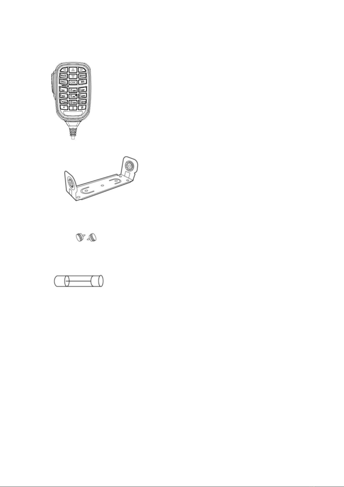
Supplied accessories
Items
Accessory No.
Quantity
Power cord BF-PC981 1
Hand microphone BF-M100 1
Support BF-ZJ001 1
Screw BF-CZLS001 2
Power fuse BF-PF801 1
Operating Manual 1
Warranty 1
Certificate 1
Power cord
Hand microphone
5
Support
Screw
Power fuse
Operating Manual
Note: Do not use non-BEIFENG genuine standard parts.
Attachment Installation of Mobile Transceiver
Accessories
Installation of Mobile Transceiver
Select a safe and convenient place inside your car to minimize impact on
passengers and yourself when your car is moving. Try to select a well-ventilated
place where avoid direct sunshine.
Use supplied self-tapping screws to fix the mixing support to your car. To
prevent injury of passengers, please use the safety support and screws provided
by the company to firmly attach the two-way radio.
Table of contents
Other Beifeng Telecom Transceiver manuals


Popular Transceiver manuals by other brands

Kenwood
Kenwood ProTalk TK-3201 instruction manual

City Theatrical
City Theatrical SHoW DMX SHoW Baby user manual

Standart Horizont
Standart Horizont HX407 owner's manual

B&G
B&G V90S quick start guide

VictelGlobal
VictelGlobal ALK300 series Operation manual

Cactus
Cactus Wireless Flash Transceiver V6 user manual


