Hopkins GR05UW User manual

E.C. HOPKINS LTD
GR05UW 5” ANGLE GRINDER
OPERATORS MANUAL
AND
PARTS LIST
E.C. HOPKINS LTD
UNIT 82, KETTLES WOOD DRIVE, WOODGATE BUSINESS PARK,
WOODGATE VALLEY, BIRMINGHAM B32 3DB
TEL NO. +44 (0)121 506 6095 FAX NO. +44 (0)121 421 8286
www.echopkins.co.uk www.underwatertools.co.uk
enquiries@echopkins-bham.co.uk
Version 1 (250118)


Contents
Page
Specifications 1
Intended Use 2
Maintenance Warning 2
Disc Information & Safety Instructions 3
General Safety 4
Safety Precautions 4~6
Kickback Warning 6
Maintenance (Before & After Use) 7
Operation 7
Disassembly 8
Assembly 8
Illustrated Parts Drawing 9
Parts List 10
Trouble Shooting 11
Warranty 12
EC Declaration of Conformity 13
Accessories 14~16

SPECIFICATION
Speed Max. 9450rpm @ 40lpm EHTMA Category ‘E’
7100rpm @ 30lpm EHTMA Category ‘D’
4750rpm @ 20lpm EHTMA Category ’C’
Wheel Internal Dia. 22.23mm (7/8”)
Wheel Outer Dia. 125mm (5”)
Spindle Thread Size M14
Flow Range 20 ~ 40lpm (5 ~ 11 US gpm)
Maximum Flow 40lpm (11 US gpm)
Hydraulic Oil ISO 32 Mineral Oil
Oil In Handle 15W/40
Pressure Relief 155 Bar (2250 psi)
System Type Open Centre (OC)
Ports -8 SAE O-ring
Hose Whips 1mtr Long
Connection 1/2” BSP Flat Face Couplers
Length 321mm
Width 65mm
Height 130mm
Weight 3 Kgs (without hoses)
Vibration TBCm/s2
Noise TBC
1

INTENDED USE
The GR05UW Angle Grinder is a portable manual lightweight tool designed to be
operated with both hands.
It is intended for grinding, sanding, cutting and cleaning of metal and stone materials.
This Grinder should only be operated by competent, trained operators.
WARNING
SERIOUS INJURY OR DEATH COULD RESULT FROM
THE IMPROPER REPAIR OR SERVICE OF THIS TOOL
IF IN DOUBT ASK
TECHNICAL HELPLINE +44 (0)121 506 6095
e-mail:- enquiries@echopkins-bham.co.uk
2

Always be sure to comply with all the accident prevention regulations when using
grinding discs and cut-off wheels. The appropriate industrial safety pictograms are
found on all discs and wheels.
Wear Safety
Goggles or
Glasses
Use hearing
Protection
Wear Safety
Gloves
Wear Safety
Goggles or
Glasses
Observe
safety
Instructions
Do Not use
for side
Grinding
Do Not use
If Broken
General Safety Guidelines
Check cut-off / grinding wheel etc
for damage before use.
Ensure tool speed does not exceed
maximum rated speed of cut-off /
grinding wheel etc.
Disconnect power source before
changing wheels or when tool is not
is in use for extended periods.
Ensure work piece is secure.
Always wear appropriate personal
protective equipment (PPE).
Never breech any restrictions to use
i.e.
Do not use if broken.
Do not use cutting disc for grinding.
Grinding Wheel Use
Cut-off Wheel Use
Mop Wheel Use
Proper Tool Mounting
Depressed Grinding
Wheels
Wheels with 4mm to 10mm
thickness
Flat and Depressed
Cut-Off Wheels
Wheels with 1mm to 4mm
thickness
3
Discs Information and Safety Instructions

GENERAL SAFETY !
The risk of serious injury or even death to yourself or others is a reality when tools and
machinery are not operated or maintained correctly.
All operators of this Angle Grinder must read this manual and fully familiarise themselves
with its operation before use.
Ensure the hydraulic power source is compatible for use with this Angle Grinder (e.g. flow
and pressure).
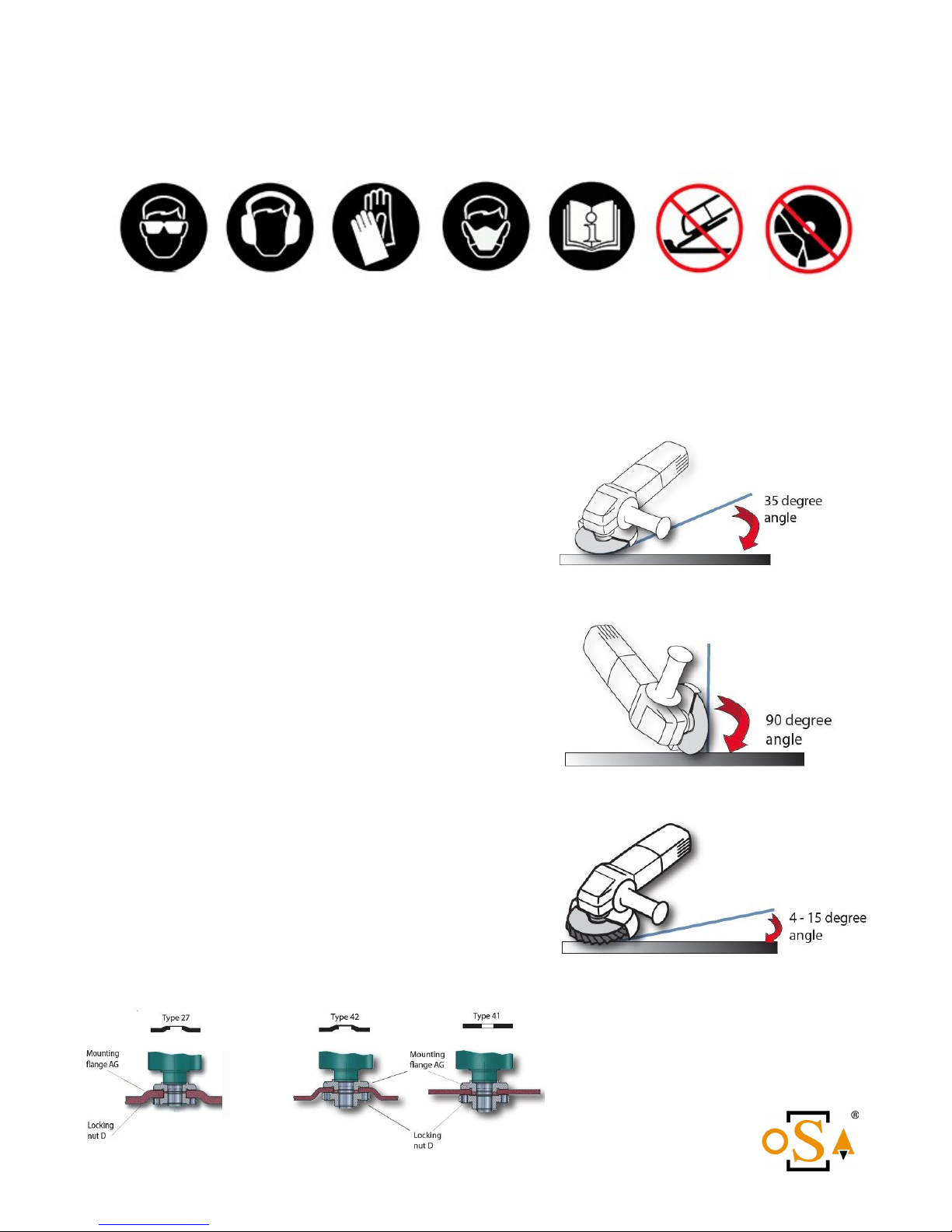
Ensure any abrasive wheel being fitted to this tool is compatible and is within the
maximum speed.
Only persons who have attended a recognised Abrasive Wheel Course (or equivalent)
and holds a valid certificate should fit abrasive wheels.
Do Not use non-reinforced cutting wheels with this Angle Grinder.
Do Not modify or fit non-approved parts without the manufacturers written consent. Any
warranty will become void and could result in injury or even death.
Do Not reverse the oil flow through the grinder as this will make the wheel rotate in
the wrong direction.
Never operate this tool when under the influence of drugs, alcohol, on medication,
tired or feeling unwell as your judgement becomes impaired and could lead to serious
injury or death, not just to yourself but others around you.
You have a duty, not just to protect yourself but also a duty of care to others.
Safety Precautions
PPE (Personal Protective Equipment). Always wear approved fire retardant protective
garments covering arms and legs if appropriate, protective helmet, suitable eye
protection, ear defenders, suitable respiratory mask (in dusty conditions), safety boots,
protective gloves.
Do not operate this tool with loose clothing and tie back long hair. As any loose
items becoming entangled may cause serious injury.
Small jets of pressurized hydraulic oil can penetrate the skin. Never check for leaks
using your hands. Should oil penetrate the skin or be inadvertently swallowed seek
medical advice immediately. Do not induce vomiting.
Hydraulic oil along with other lubricants and greases can cause eczema. Should oils
etc. come into contact with bare skin wash off immediately with warm soapy water.
Inspect the abrasive wheel for damage, cracks, excessive or uneven wear. Discard
any wheel that has any defects or has been dropped.
4

Safety Precautions (continued)
Do not forcibly fit an abrasive wheel as this will pre-stress the wheel and may lead to
premature failure.
Disconnect from the power source when changing the wheel or working on the
grinder. When a new wheel has been fitted run the Grinder for about 15 seconds to
ensure the wheel runs true and there is no abnormal vibration.
Never operate the tool without the wheel guard.
Before commencing grinding carry out a risk assessment and any procedures put in
place are followed.
Ensure any persons cannot wander in front or to the sides of the operator whilst
grinding. To avoid the risk of injury to others cordon off the area.
Make sure the working floor area is clean so as to avoid any slipping or tripping
hazards.
This Grinder will produce sparks. Remove all flammable liquids and combustible
materials from the vicinity.
Do not use in an explosive environment.
Hold the Angle Grinder firmly with both hands at all times whilst operating.
Do not overreach, ensure you keep your balance and sure footing at all times.
Make sure that the work piece is secured and cannot move whilst grinding or cutting.
Ensure the wheel guard is positioned correctly (with the closed side towards the
operator) and keep all parts of the body away from the rotating wheel.
Do not start the grinder with the wheel in contact with a surface. Always introduce the
free spinning wheel to the work piece to be ground or cut.
Do not use a cutting wheel to grind with. Side loading the thin wheel will cause the
wheel to shatter which may result in injury or death.
When cutting do not twist or force the wheel to cut, this will cause the wheel to
shatter. Guide the wheel in a straight line applying gentle pressure and let the cutting
wheel do the work.
Never walk around with the Grinder running.
Be sure to check the area for buried utility cables or pipes. Do not operate where you
cannot be sure of their presence. It could result in serious injury or death.
5

Safety Precautions (continued)
Do not use toothed wood cutting wheels. This type of wheel will increase the risk of
kickback which could result in serious injury.
Do not use worn down wheels from larger tools. They will not be compatible with this
Grinder.
Do not use reducing bushes to enable the fitting of wheels with a larger hub size.
Replace illegible, damaged or missing safety labels. Keep this manual clean and
readily available so it can be referred to by all operators.
KICKBACK WARNING
Be aware of ‘Kickback’ during operation. This happens when a grinding or cutting wheel is
misaligned, binds or is pinched in the work piece. The Grinder reacts violently lifting out of
the work piece back towards the operator and could result in serious injury especially if
the wheel shatters.
Kickback occurs due to operator error, and injury can be avoided by taking proper
precautions and following the procedures listed.
Grip the Grinder firmly by the side handle and around the trigger / handle. Always
use both hands when operating be prepared for the unexpected when using.
Position your body away from the line of any kickback should it occur.
When using a cutting wheel always cut in a straight line. Do not twist the wheel or try
to cut round corners, this puts a side load on the wheel and it will either jam or shat-
ter causing ‘kickback’.
Do not force the wheel to cut. Only apply light pressure and let the wheel do the
work.
Do not start the Grinder with the wheel in contact with the work piece. Introduce a
free spinning wheel slowly to the work piece.
Complacency can be a killer. The attitude of ‘I’ve been using an angle grinder
for years I know what I’m doing it’s never happened to me’ could be your un-
doing. Stay alert, Stay alive.
6

Maintenance
Before use:-
1. Check hose whips for damage or exposed wire braid and replace as necessary.
2. Check the tightness of all fasteners.
3. Check the trigger safety catch and trigger moves freely.
4. Remove oil filler plug (1) and make sure the grinder body has the correct amount of lubricating
oil (15W/40). Correct oil level is achieved when the grinder is held horizontal with the spindle
pointing down. Oil should then be level with bottom of the filler hole.
5. Check the condition of the disc and replace as necessary.
After use:-
1. Ensure any faults with the grinder are reported and do not use it until rectified.
2. Wash the grinder off with clean water and work a light oil to the moving parts e.g. valve spool,
trigger and safety catch.
3. Store away in a clean environment.
Operation
1. Make sure that the power pack has a maximum output flow of 40 Litres Per Minute and that the
maximum system pressure is no more than 155 Bar (2250 psi).
2. Ensure the hydraulic circuit is of the open centre (OC) type.
3. Wipe the flat face couplings with a clean cloth.
4. Connect the return hose first to the power pack and then the pressure hose. When
disconnecting, uncouple the pressure hose first and the return hose last so as to minimize any
pressure being trapped in the grinder. If the couplings will not connect due to pressure within
the grinder, slowly loosen off one of the couplings allowing some oil to leak out. Re-tighten the
coupling and connect to the power pack.
5. Start the power pack and move the ‘ON/OFF’ lever to the ‘ON’ position.
6. Hold the grinder with both hands i.e. one hand grasping the side handle and the other hand
around the trigger.
7. Operate the trigger and ensure the disc rotation is correct (CW if viewed from above) and that
there are no leaks.
8. Do not start the grinder with the disc in contact with the work surface.
Note:- For operator comfort and better control over the Grinder when used in awkward
places, the Grinder head can be rotated in relation to the trigger by loosening the
cap screw (8) and rotating the head to the desired position then retighten the cap screw.
WARNING:- Disconnect the Grinder from the power source before carrying out
this procedure.
7

Disassembly
1. Undo the 2 hose whips and allow them to drain into a suitable container.
2. Remove the grinding disc, support flange (16) and disc guard (50).
3. Undo the 4 screws (12) and pull the bearing housing (15) from the grinder body (19). Note,
some oil will spill from the body when it is removed.
4. Hold the gear (9) in a vice with soft jaws and undo the hex screw (2). Remove washer (3),
pull the gear off the bearing shaft (18) and remove the key (4).
5. Remove the circlip (10) and tap the bearing shaft out through the bearings (14) and shaft seal
(13).
6. Remove cap screw (8) and pull the grinder body (19) away from the handle (20).
7. Undo the cap screw (40) and remove the trigger (44).
8. The valve spool (36) needs to be drawn out of the body from the trigger side. Using a 5mm
hexagon key push on the button head screw (33) to compress the valve spring so the valve spool
extends beyond the valve body. Clamp the valve spool with a pair of grips and undo screw (33).
Remove the valve spring washer (32) and valve spring (34) and withdraw the valve spool out
through the trigger side of the valve block (35).
9. Remove the eight button head screws (22) and the grinder should separate into three
sections (valve block (35), gear housing (31) & handle c/w handle housing (20 & 27).
10. Remove the two gears (30 & 38). Clamp the handle housing (27) in a vice and
unscrew the handle (20).
11. Remove circlip (42) and take out the seal housing (24). Split the two halves of the housing to
remove the shaft seal (25).
12. Hold the gear (5) in a vice with soft jaws and undo the hex screw (2). Pull the gear off the
shaft and remove the key (4).
13. Slide the drive shaft (21) out from the handle.
14. To remove bearings (7,14 & 41) it is best to warm up the housings first then tap them out
using a suitable drift. Fit new bearings whilst the housings are still warm.
16. Remove all seals and discard.
Assembly
1. Assembly is the reverse procedure of the above.
2. With new bearings fitted replace all the seals.
3. When doing up the eight button head screws (22), tighten them in an opposite sequence in
stages making sure the shaft still rotates freely.
4. Fit new O-rings (55) onto the tail hoses. The tail hose with the female coupling (knurled sleeve)
connects to the ‘P’ port and the hose with the male coupling connects to the ‘T’ port.
5. With the assembled grinder horizontal, bearing shaft pointing downwards pour 15W/40 oil in
through the filler hole (1) until it’s level with the bottom of the threaded hole. Re-fit the filler
plug.
6. Finally run the Angle Grinder and check for any oil leaks.
Remember, a badly maintained or repaired tool
could lead to serious injury.
8

GR05UW PARTS ILLUSTRATION
9

10

Troubleshooting
Below are various types of faults that may be encountered. Should a fault persist please call our
technical helpline +44 (0)121 506 6095 for assistance.
11
PROBLEM PROBABLE CAUSE REMEDY
Grinder runs slow
Incorrect hydraulic flow
Excessive back pressure
Hydraulic oil viscosity too thick
Flow test power pack
Check return line for restrictions
Raise oil temperature
Change oil to a thinner viscosity
Grinder gets hot Incorrect hydraulic flow
Oil Cooler not working
Oil Cooler matrix blocked
Hydraulic Pump is worn
Flow test power pack
Check cooler electrics
Clean matrix with compressed
air
Replace pump
Leaking oil around
Bearing shaft
Shaft seal worn Fit new seal
Grinder runs in
reverse
Pressure and return hoses on the
wrong way
Check system for correct flow
path and rectify
Oil leaking from valve
spool
Seals worn Remove valve spool and
replace seals
Grinder not working Power pack not switched on
Coupling blocked
Mechanical failure
Switch power pack on
Check couplings and remove
blockage
Disassemble grinder and check
for damage

WARRANTY
This product is guaranteed (subject to normal wear and tear) against defective parts and faulty
workmanship for a period of 12 months from date of purchase.
It does not cover:-
Parts already covered by original equipment manufacturers own warranties already in place.
Failure of parts due to lack of maintenance and services.
Any failure due to non-genuine parts fitted.
Rubber products.
Product subjected to misuse/abuse or being neglected in any way.
Being modified in any way without prior written consent of E.C. Hopkins Ltd.
In case of disagreement between parties as to whether it is warranty or not, the failed part will be
returned to the supplier for inspection at the customers cost. The findings by that supplier as to why
the part failed will be binding.
With an ongoing design and development program E.C. Hopkins Ltd reserve the right to alter the
design or specification of any product without prior notice.
12

EC DECLARATION OF CONFORMITY
IM.J. Newman
of Newcat Plant Services Ltd Unit 1, Beta Block, Orchard Trading Estate,
Toddington, Cheltenham, Glos. GL54 5EB
Declare that:
Equipment HYDRAULIC ANGLE GRINDER
Model GR05UW
Serial Numbers 001
In accordance with the following directives:
2006/42/EC Machinery Directive.
Has been designed and manufactured to the following specifications:
BS EN ISO 12100:2010 Safety of Machinery: Basic Concepts, General Principles for design
BS EN ISO 4413:2010 Safety Requirements for Fluid Power Systems Hydraulics
I hereby declare that the equipment named above has been tested and found to
comply with the relevant sections of the above referenced specifications. The unit
complies with all essential requirements of the Directives. The technical document is
kept by: M.J. Newman, Newcat Plant Services Ltd, Unit 1, Beta Block, Orchard Trading
Estate, Toddington, Cheltenham, Gloucestershire GL54 5EB
Signed:
Name: M. J. Newman
Position: Design & Technical Director. Date:
13

Descripon
Applicaon
Materials
Part Number
Size
Max Rang
5” Diameter Bonded Abrasive Grinding Disc for Stone
Depressed Centre High Performance, minimal vibraon & long life
Grinding Masonry, Stone, Concrete
Stone, Brick, Concrete, Ceramics
GW578DCM
125mm x 6.4mm
12’200rpm
Descripon
Applicaon
Materials
Part Number
Size
Max Rang
5” Diameter Bonded Abrasive Grinding Disc for Metal
Depressed Centre High Performance, minimal vibraon & long life
Grinding Pipe, Structural, Solid or Plate
Steel, Stainless Steel
GW578DCS
125mm x 6.4mm
12’200rpm
Descripon
Applicaon
Materials
Part Number
Size
Max Rang
5” Diameter Bonded Abrasive Cung Disc for Metal
Depressed Centre High performance, minimal vibraon & long life
Cung Pipe, Structural, Solid and Plate
Steel, Stainless Steel
CW578DCS
125mm x 2.5mm
12’200rpm
Descripon
Applicaon
Materials
Part Number
Size
Max Rang
5” All-Grind Diamond Grit Grinding Disc
Durable, Long Life with the ability to grind a wide range of materials
General Grinding / Various Materials
All Purpose, Concrete, Stone, Steel & Alloys, Composite, PVC, Wood
AG125-22
125mm
12’250rpm
Descripon
Applicaon
Materials
Part Number
Size
Max Rang
5” All-Cut Diamond Grit Cung Disc
Durable, Long Life with the ability to cut a wide range of materials
General Cung / Various Materials
All Purpose, Concrete, Stone, Steel & Alloys, Composite, PVC, Wood
AC125-22
125mm x 2.5mm
12’250rpm
GR05 ACCESSORIES
14
All Hydraulic Tools, parts, accessories and allied equipment are subject to design improvements, specicaon and price changes at any
me without noce and with no obligaon to units already sold. Weights, dimensions and operang specicaons listed herein are sub-
ject to change without noce. Where specicaons are crical to your applicaons, please consult us.

GR05 ACCESSORIES
15
All Hydraulic Tools, parts, accessories and allied equipment are subject to design improvements, specicaon and price changes at any
me without noce and with no obligaon to units already sold. Weights, dimensions and operang specicaons listed herein are sub-
ject to change without noce. Where specicaons are crical to your applicaons, please consult us.
Descripon
Applicaon
Materials
Part Number
Size
Max Rang
5” Diamond Grinding Cup DS300 B
Cup Grinding Wheel with 18 segments
High Stock Removal Performance
Concrete, Stone, Construcon Material
325362
125mm x 5mm
12’200rpm
Descripon
Applicaon
Materials
Part Number
Size
Max Rang
5” Diamond Cung Disc DT 600 U
Fast Cung Performance, Long Life
Cung
Concrete, Stone, Brick, Construcon Materials
322631
125mm x 2.4mm
12’200rpm
Descripon
Applicaon
Materials
Part Number
Size
Max Rang
Cup Wire Brush 100mm Crimped Steel Bristles
General purpose cup wire brush
Surface preparaon, Rust removal, Cleaning
Various, Inc. Steel, Stainless Steel & Glass Fibre
CWB100-CB14
100mm x M14 Threaded Bore
8’500rpm
Descripon
Applicaon
Materials
Part Number
Size
Max Rang
Cup Wire Brush 100mm Twisted Knot Steel Bristles
Hard wearing cup brush with good material removal
De-burring, De-scaling, Marine growth removal, Paint removal
Various, Inc. Steel, Stainless Steel & Glass Fibre
CWB100-TK14
100mm x M14 Threaded Bore
8’500rpm
Descripon
Applicaon
Materials
Part Number
Sizes
Max Rang
Bevel Wire Brush 100mm Twisted Knot Steel Bristles
Hard wearing bevel brush with good material removal
De-burring, De-scaling, Marine growth removal, Paint removal
Various, Inc. Steel, Stainless Steel & Glass Fibre
BWB100-TK14
100mm x M14 Threaded Bore
12’500rpm

GR05 ACCESSORIES
16
All Hydraulic Tools, parts, accessories and allied equipment are subject to design improvements, specicaon and price changes at any
me without noce and with no obligaon to units already sold. Weights, dimensions and operang specicaons listed herein are sub-
ject to change without noce. Where specicaons are crical to your applicaons, please consult us.
Descripon
Applicaon
Materials
Part Number
Size
Max Rang
5” Rapid Strip Disc DPC, Extra Coarse, Harder Density
Synthec bres and coarse silicon carbide grains
Light Marine Growth, Rust & Paint removal. Surface Preparaon
Various, Inc. Steel, Stainless Steel & Glass Fibre
RSD30655
125mm DPC
12’000rpm
Descripon
Applicaon
Materials
Part Number
Sizes
Grit
Max Rang
5” Conical Fibre Discs (40/80/120 Grit) DPC
Zirconium, excellent material removal and long life
Ideal for edge grinding, surface preparaon & cleaning, De-rusng
Steel, Stainless Steel
CFD02315 CFD02318 CFD02326
125 125 125
40-Grit 80-Grit 120-Grit
12’250rpm
Descripon
Applicaon
Materials
Part Number
Size
Max Rang
4” Swirl-O
Stainless Steel housing with 21 cuers
De-Scaling, Marine Growth Removal, Paint Removal
Various, Inc. Steel, Stainless Steel & Glass Fibre
50400MM
100mm x M14 Threaded Bore
6000rpm

.C. HOPKINS LTD
UNIT 82, KETTLES WOOD DRIVE
WOODGATE BUSINESS PARK,
BIRMINGHAM B32 3DB
TEL NO. +44 (0)121 506 6095 FAX NO. +44 (0)121 421 8286
www.echopkins.co.uk www.underwatertools.co.uk
enquiries@echopkins-bham.co.uk
Table of contents