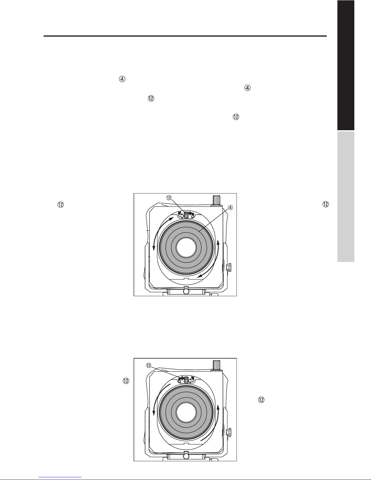
Horseman TS-PRO User manual

取扱説明書
Instruction Manual
ホースマン TS プロ
HORSEMAN TS-PRO

2
仕様
使用上のご注意
その他の注意
各部の名称/フロントユニット
フロントユニットのセット
●レンズの取付け
●レンズ位置の調整
●レンズパネルの取外し
●ベースユニットの取付け方
●カメラマウントの取付け方
カメラの取付け
●カメラの取付け方
カメラに19mmロッドが無い場合
カメラに19mmロッドが有る場合
TS-PROの操作/フロントユニット
●ピント合わせ
アオリ操作/フロントユニット
●ティルト(前後)
●ティルト(左右)
●シフト(前後)
●シフト(左右)
各部の名称/ベースユニット
ベースユニットの組み立て
●ハンドグリップの取付け方
●延長ロッドの取付け方
SPECIFICATIONS
CAUTIONS IN USE
CAUTIONS
NOMENCLATURES / FRONT UNIT
ASSEMBLING FRONT UNIT
Attaching Lens ●
Adjustment of Lens Position ●
Removing Lens Panel ●
Attaching Base Unit ●
Attaching Camera Mount ●
ATTACHING CAMERA
Attaching Camera Body ●
In case the user does not have his 19mm Rods
In case the user has his 19mm Rods
OPERATING TS-PRO
Focusing Operation ●
CAMERA MOVEMENTS
Tilt ●
Tilt (L/R) ●
Vertical Shift ●
Lateral Shift ●
NOMENCLATURES / BASE UNIT
ASSEMBLING BASE UNIT
Attaching Hand Grip ●
Attaching Extension Rods●
この度はホースマン TS プロをお買い上げ頂き、ありがとうございます。
ご使用の前に必ずこの取扱説明書をよくお読みください。
お読みになったら大切に保管して下さいます様お願い申し上げます。
Thank you for your purchase of the HORSEMAN TS-PRO.
Before operating the HORSEMAN TS-PRO, we suggest reading this Instruction Manual
carefully.
--------------------------------------
------------------------------------
---------------------------------------------
-----------------
-----------------------
-----------------
---------------
------------------------------
-------------
----------------------
------------------------
-----------------
----
--------------
------------------------
----------------------------------------------
---------------------------------------
----------------------------------
----------------------------------
3
3
12
10
11
11
4
5
5
5
6
6
7
7
8
9
9
9
9
TS-PRO / FRONT UNIT TS-PRO / BASE UNIT
フロントユニット / FRONT UNIT
フロントユニット / BASE UNIT
------------------------------------------------------
----------------------------------------
-------------------------------------------
------------------
-------------
-------------------
---------------
----------------------------
------------------------
-------------------
-------------
-------------
-----
-----
------------------------------
----------------------------
----------------------------
------------------------------
------------------------------

3
型 式
Type
カメラのレンズマウントに装着
し、ティルト、シフトの各アオリを
可能とする付属装置
35mm
ティルト: 前20°後15°
/左右各15°
シフト: 左右各30mm
/上下各15mm
JIS 1/4インチ/3ヶ所 (3/8インチ可)
交換式
交換式
フロントユニット:
H220 × W170 × D60mm
ベースユニット(ロッド付き):
H150 × W170 × D140mm
35mm
Tilt : 20°forwards / 15°Backwards
/ 15°each (L/R)
Shift : 30mm each (L/R)
15mm each (U/D)
1/4 inch, 3 places (3/8 inch)
Interchangeable
Interchangeable
仕 様 SPECIFICATIONS
Auxiliary equipment allowing tilt and
shift movements when attached to
the lens mount of a camera.
※各可動部の操作の前には、必ずロックを解除
してください。ロックが効いている状態で無
理な操作を行うと、駆動機構やロック機構に
悪影響を与えることがあります。
※この取扱説明書に述べた各モジュールの分解
組立は、簡単な設計になっていますが、それ以
上の分解再組立は精度保持上高度の技術を必
要としますので、分解はしないでください。
1. Be sure to release the appropriate lock
before operating each camera movement.
Forced operation in the locked position may
damage the driving and locking mechanisms.
2. Assembling or disassembling the TS-PRO is
relatively easy, but refrain from disassembling
beyond the limits of each module as described
in the instructions.
使用上のご注意 CAUTIONS IN USE
アオリ機構
Camera Movements
重量
Weight
Front Unit
H220 × W170 × D60mm
Base Unit (w / Rods)
H150 × W170 × D140mm
フロントユニット:1.2kg
ベースユニット:1.1kg
Front Unit : 1.2kg
Base Unit : 1.1kg
三脚ネジ穴
Tripod Socket
カメラマウント
Camera Mount
レンズパネル
Lens Panel
トラック繰出量
Track Extension
外形寸法
Dimensions
TS-PRO / FRONT UNIT TS-PRO / BASE UNIT

4
シフト(上下)ノブ
フロントフレーム
蛇腹
レンズパネル
ティルト(前後)ロックノブ
アーム
シフト(左右)ロックノブ
ティルト(左右)ロック解除レバー
フォーカシングノブ
ロッド取り付け口
ロッド固定レバー(フロントユニット)
レンズ位置調整ロックノブ
シフト(上下)スケール
シフト(左右)スケール
フォーカシングロックレバー
カメラマウント
①
②
③
④
⑤
⑥
⑦
⑧
⑨
⑩
⑪
⑫
⑬
⑭
⑮
⑯
①
②
③
④
⑤
⑥
⑦
⑧
⑨
⑩
⑪
⑫
⑬
⑭
⑮
⑯
Knob for Vertical Shift
Front Frame
Bellows
Lens Panel
Lock Knob for Tilt
Struts
Lock Knob for Lateral Shift
Lock Release Lever for Tilt
Focusing Knob
Lod Slot
Rod Locking Lever
Lens Position Adjustment Locking Knob
Vertical Shift Scale
Lateral Shift Scale
Focusing Lock Lever
Camera Mount Adapter
各 部 の 名 称 / フロントユ ニット
NOMENCLATURES / FRONT UNIT
TS-PRO / FRONT UNIT TS-PRO / BASE UNIT

5
フロントユ ニット の セット
ASSEMBLING FRONT UNIT
● Attaching Lens●レンズの取付け
●レンズ位置の調整
レンズパネルを回転することでレンズの絞り指
標を見やすい位置に調整します。
レンズを取付けたパネル をTS-PROに対して
時計回りに回転させてネジ込みます。
※この時レンズ位置調整ロックノブ が締め付
けられていることをご確認ください。(緩んでい
ると取付けることができません)
1. Rotate clockwise toward the TS-PRO and
screw in the Panel with a lens mounted.
【NOTE】 When rotating and screwing in the
panel, check if the Lens Position Adjustment
Locking Knob are securely fastened. (If they
are loose, the lens cannot be mounted.)
● Adjustment of Lens Position
Adjust the lens to a position where the
diaphragm index of the lens is clearly visible.
●レンズパネルの取外し
レンズ位置調整ロックノブ
を締め、レンズパネル自体を
時計と反対方向に回転させて
取外します。
Be sure to tighten Lens
Position Adjustment Locking
Knob before taking off
Lens Panel by turning it anti-
clockwise.
● Removing Lens Panel
❶
❷
❷
❶Loosen three Lens Position
Adjustment Locking Knob
by half-turning knob.
*If Lens Position Adjustment
Lock are securely fastened
at this time, Lens Panel will
become loose, resulting in
unstable mounting of the
lens. When adjusting the
lens position, be sure to
loosen the Locking Knob.
(Do not loosen the Locking
Knob too much.)
❶レンズ位置調整ロックノ
ブを半回転ほど緩めま
す。
※この時レンズ位置調整
ロックノブが締め付けら
れているとレンズパネル
自体が緩み、レンズが不安
定になります。位置調整時
は必ず調整ノブを緩めて
行ってください。(注)緩め
過ぎにご注意ください。
❷Shift the diaphragm index to a position
where it is easy to see, and then re-fasten the
Lens Position Adjustment Locking Knob.
❷絞り指標を見やすい位置まで回転させ、レン
ズ位置調整ロックノブを再度締め付けます。
TS-PRO / FRONT UNIT TS-PRO / BASE UNIT

6
●ベースユニットの取り付け方
カメラ側に19mmロッドが無い場合、TS-PROの
ベースユニットを使用します。ベースユニット
の詳細はP10〜11をご覧ください。
❶ベースユニットのロッドス
トップネジ を左右共に外
します。
❷ロッド をフロントユニッ
トのロッド取付け口 に差
込みます。
❸位置を決め、フロントユ
ニットのロット固定レバー
を締付けてストップネ
ジも元通りに取付けます。
❶Unscrew Stopper .
❷Insert Rod through Rod
Slot .
❸Tighten Rod Rocking
Lever once the
position of Front Unit is
determined. Put Stopper
back on.
※カメラ側に19mmロッドが装備されている場
合は、そのロッドを使用します。
*In case the user's rods are being used with
camera, put Front Unit onto the rods.
❶
❷
❸
ご使用になるカメラ用のカメ
ラマウント をTS-PROのフ
ロントユニットに時計回りに
ネジ込んで取付けます。
●カメラマウントの取り付け
Attach Camera Mount
Adaptaer to the camera
body by rotating Camera
Mount Adaptaer clockwise.
Assemling Base Unit, see page 10-11.
●Attaching Camera Mount
●Connecting Front and Base Units
TS-PRO / FRONT UNIT TS-PRO / BASE UNIT
T S - P R O の セット/ フロントユ ニット
ASSEMBLING TS-PRO / FRONT UNIT

7
●カメラの取り付け ●Attaching Camera Body
ベースユニットをフロントユニットに取付けて
からカメラをセットします。(P10-11参照)
Connect Front and Base units first as per page
10-11.
Put Front Unit through his Rods and follow the
above 1 through 3 procedures.
[カメラ側に19mmロッドが無い場合]
[In case the user does not have his 19mm Rods]
[In case the user has his 19mm Rods][カメラ側に19mmロッドが有る場合]
フロントユニットのロッド取付け口 にカメラ
のロッドを差込んで位置を決め、ロッド固定レ
バー を締付けます。
カメラのレンズマウント部をカメラマウント
に取付けます。
❶
❸
❷
❶カメラの三脚ネジ穴を、
ベースユニットのカメラ
取付けネジ に合わせて、
カメラ固定ノブ を締付
けます。
❷カメラのレンズマウント
部をフロントユニットの
カメラマウントに取付
けます。
❸カメラ取付け台固定ノブ
を緩めて、カメラ取付け
台の高さを調整します。
❶Mount the camera body
by using Camera Mounting
Screw .
❷Attach Lens Mount to the
camera body.
❸Adjust the height of camera
body and tighten Height
Adjustment Locking Knobs
to secure it.
カメラの取付け / フロントユニット
ATTACHING CAMERA / FRONT UNIT
TS-PRO / FRONT UNIT TS-PRO / BASE UNIT

8
ピント合わせは、フロントユ
ニットのロッド固定レバー
を緩め、フロントユニットを
ロッド上で前後に移動させて
調整します。
ピントの微調整はフォーカシ
ングノブ を使います。
Focusing can be obtained
by thrusting the entire Front
Unit back and forth. Tighten
Rod Locking Lever once
the position is determined.
Focusing Knobs may be
used for fine focusing.
●ピント合わせ
※マイクロフォーサーズカメラをご使用の場合 ※For Micro Four Thirds camera user;
使用するレンズによってはカメラとフロントユ
ニットの距離を縮めないと無限でピントが出な
い場合があります。
Please be aware that shorter distance
between the lens and the camera mounts
may be required for focusing at infinity
with using the Micro Four Thirds camera.
● Focusing Operation
ハンドグリップは取外し、ト
ラック繰り出しを最大までカ
メラに近づけてご使用くださ
い。
※ベースユニットの詳細は
P10-11 をご覧ください。
It is advisable to remove
Hand Grip when used with
Micro Four Thirds camera as it
may interfere the focusing at
infinity or far subject.
* For assembling Base Unit,
see page 10 ~ 11.
TS-PRO / FRONT UNIT TS-PRO / BASE UNIT
T S - P R O の 操 作 / フロントユ ニット
OPERATING TS-PRO / FRONT UNIT

9
ティルト(前後)ロックノ
ブをゆるめ、手でフロン
トフレーム をティルト
させ、必要な角度が得られ
たところでロックします。
ティルト(前後)
ティルト(左右)
シフト ( 左右 )
Loosen the Lock Knob for Tilt ,
tilt the Front Frame and lock
it in position when the desired
angle is set.
Lateral Shift
Tilt
Tilt (L/R)
Vertical Shift シフト(上下)
Push down on the Lock Release
Lever for Tilt , and the lens
standard can be now tilted left
or right 15°each way. When
the lens standard has been
tilted to the position desired,
remove your finger pressure,
and the lens standard will hold
in position. At zero position, the
lens standard is click stopped.
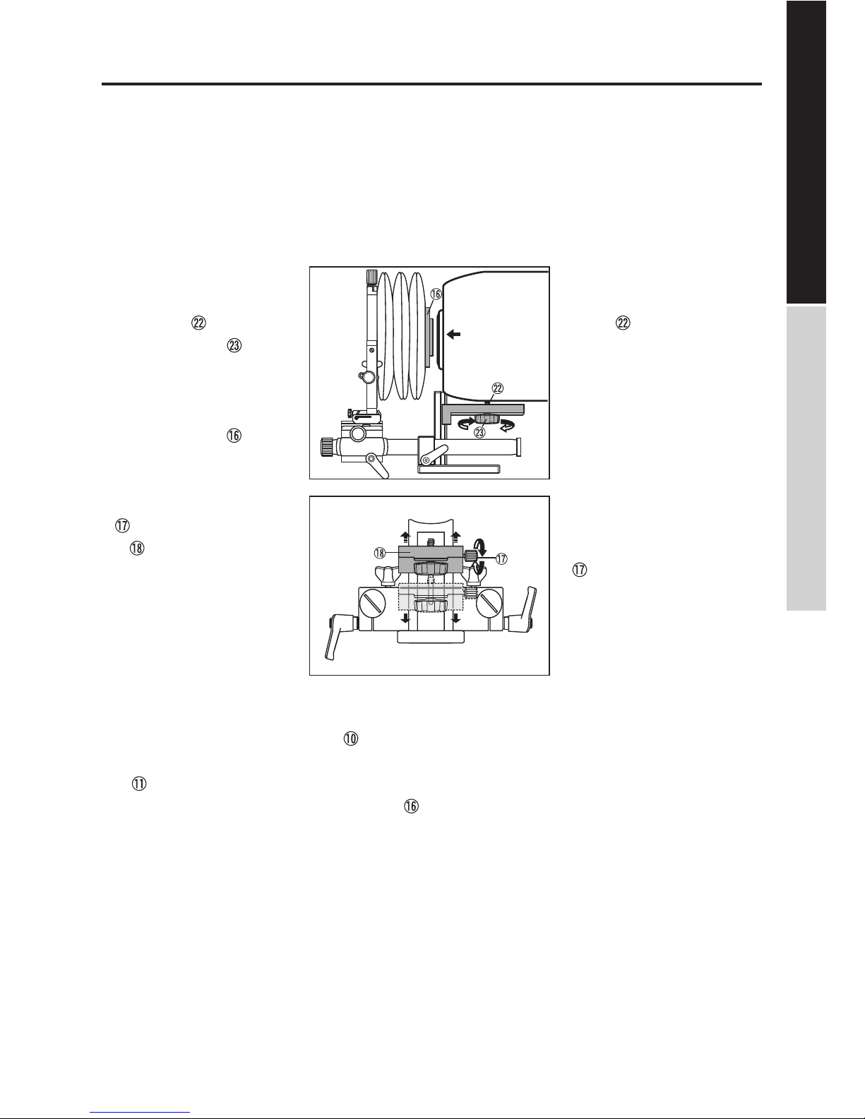
Loosen the Lock Knob for Lateral
Shift which is prepared at the
center of the lower part of the lens
standard. Thrust the lens standard
to left or right laterally. Stop and
tighten the Shift Locking knob
when the lens standard has been
crossed to the position desired.
Movement distances are shown
in mm on Lateral Shift Scale .
The lens mount goes up and
down when Knob for Vertical
Shift is rotated.
Movement distances are shown
in mm on Vertical Shift Scale .
ティルト(左右)ロック解
除レバー を押し下げた
まま、レンズスタンダード
部をティルトし、必要な角
度が得られたとこ
ろでロックレバー
を離します。
シフト(左右)ロックノブ
を緩め、レンズスタン
ダードを左右に動かしま
す。必要な移動量が得られ
たらロックします。
移動量はシフト
(左右)スケール
上にmmで示され
ます。
シフト(上下)ノブ を回
すとレンズマウントが上
下します。
移動量はシフト
(上下)スケール
上にmmで示
されます。
アオリ操作 / フロントユニット
CAMERA MOVEMENTS / FRONT UNIT
TS-PRO / FRONT UNIT TS-PRO / BASE UNIT

10
TS-PRO / FRONT UNIT TS-PRO / BASE UNIT
各 部 の 名 称 / ベース ユ ニット
カメラ取付け台固定ノブ
カメラ取付け台
グリップ取り付けネジ
ロッドストップネジ
ロッド固定レバー(ベースユニット)
カメラ取り付けネジ
カメラ固定ノブ
ハンドグリップ
ハンドグリップバー
19mmロッド
19mm延長ロッド(付属)
三脚ネジ穴
Height Adjustment Locking Knobs
Camera Mounting Plate
Hand Grip Mounting Screws
Stopper Screw
Front Unit Retaining Lever
Camera Mounting Screw
Camera Mounting Knob
Hand Grip
Hand Grip Support Arm
Rod
Extension Rod
Tripod Screw Socket
⑰
⑱
⑲
⑳
⑰
⑱
⑲
⑳
NOMENCLATURES / BASE UNIT

11
ベース ユ ニット の セット
ASSEMBLING BASE UNIT
●ハンドグリップの取り付け方 ●Mounting Hand Grip
❶ベースユニットのハンドグ
リップ取付けネジ を2つ
取外します。
❶Remove two Hand Grip
Mounting Screws .
❷ハンドグリップバー の取
付け穴とベースユニットの
穴の位置を合わせ、グリッ
プ取付けネジを入れて締付
けます。
❷Place Hand Grip Support
Arm on Base Unit
and screw in Hand Grip
Mounting Screws.
ハンドグリップ はハンド
グリップバー から取り外
し、反対側に取付けることが
できます。
Hand Grips may be
attached upside down as
required.
●延長ロッドの取り付け方 ●Attaching Extension Rod
❶ロッド からストップネ
ジを外して延長ロッド
をネジ込みます。
❷延長ロッド の反対側に
❶で取り外したストップ
ネジを取付けます。
❶Unscrew Stopper and
add the optional Extension
Rod.
❷Put the removed Stopper
on the other end of
Extension Rod .
付属の延長ロッド を継ぎ
足し、長くすることができ
ます。
The optional Extension Rod
can be attached for extra
extension.
❶
❷
TS-PRO / FRONT UNIT TS-PRO / BASE UNIT

その他のご注意
CAUTIONS / FRONT UNIT & BASE UNIT
●キヤノン EOS マウントおよびニコン F マウ
ンをご使用になる場合、これらは凹み式のた
め、鏡筒後部の口径が大きいレンズはレンズ
マウントに装着できない場合があります。
●使用するレンズによってはアオリ操作に制限
が生じる場合があります。
●レンズの絞りはカメラの露出計と連動しませ
ん。露出測定は絞り込み測光となります。
●デジタル一眼レフカメラ用の AF レンズの場
合、絞りは開放となります。
●カメラ内蔵の TTL 露出計はアオリを使用した
場合正しく測光しないことがあります。
●カメラマウントによりアオリ操作時ケラレが
生じる事があります。
●アオリ操作、あるいは長焦点レンズの使用
時、ミラー切れを生ずることがあります。
●アオリを使った撮影の場合は、事前にケラレ
が無いことをモニタやファインダ上で確認さ
れることをお薦めします。
● Please be aware that the excessive diameter
of rear section of lens to be mounted on
Canon EOS or Nikon F mount may not fit into
Lens Mount.
● The movements may be restricted due to the
image circle of the lens to be used.
● Exposure needs to be set manually on
aperture priority.
● The built in through-the-lens of digital single
lens reflex camera may not work when the
movements are applied.
● Image may be vignetted by single lens reflex
camera mount opening and/or built-in mirror
when movements are being used.
● Excessive use of movements or use of long
focal length lens may cause built in mirror
vignetting.
● Test monitoring is recommended to make
sure there is no vignetting on the image
when using the movements.
株式会社ケンコープロフェショナルイメージング
〒164-0001 東京都中野区中野5-68-10 KT中野ビル
TEL.03-6840-3622 FAX.03-6840-3861
5-68-10 Nakano, Nakano-ku, Tokyo 164-0001, Japan
E-mail . [email protected]
www.kenko-pi.co.jp
● "HORSEMAN"" ホースマン " は株式会社ケンコー プロ
フェショナル イメージングの登録商標です。
●この取扱説明書は 2015 年 5 月現在のものです。
●この取扱説明書に記載の製品に関する外観・仕様など
は予告無しに変更する場合があります。
● "HORSEMAN" is a registered tredemark of Kenko
Professional Imaging, Tokyo, Japan.
● Specications are subject to change without notice.
Other manuals for TS-PRO
1
Table of contents
Other Horseman Camera Accessories manuals
Popular Camera Accessories manuals by other brands

Moog Videolarm
Moog Videolarm SView PFD7C12N-3 Installation and operation instructions

PROAIM
PROAIM SL-ALPN-01 Assembly manual

Turbo Energy
Turbo Energy Lithium Series manual

PROAIM
PROAIM Kite-22 Ultimate Package Setup and operation manual

Vinten
Vinten HS-105P Operation, installation & maintenance instructions

Zacuto
Zacuto Sony FS7 Recoil Kit manual