Hotpoint 76769 Operating and installation instructions

Indesit Company UK Ltd
© 2012 Reg. Office: Peterborough PE2 9JB Registered in London: 106725
Service
Information
HOTPOINT
LUCE
WINE CELLARS
Models Comm.
Covered Code
WL24HP 76770
WL36HP 76769
Energy Band A Models
WL24AHP 78417
WL36AHP 78416
5407680 Issue 1 Dec. 2012
SM003423 ~ C00290011

2 of 15
Service Manual UK
Indesit
Company
English
Health & Safety Information
Applicable to Servicing Refrigeration Products Containing R134a
General
1. This manual is not intended as a comprehensive repair/maintenance guide to the appliance.
2. It should only be used by suitably qualified persons having technical competence, applicable
product knowledge, suitable tools and test equipment.
3. Servicing of electrical appliances must be undertaken with the appliance disconnected.
(unplugged from the electrical supply).
4. Servicing must be preceded by earth continuity and insulation checks.
5. Personal safety precautions must be taken to protect against accidents caused by sharp edges
on metal and plastic parts.
6. After servicing, the appliance must be rechecked for electrical safety.
Refrigerant R134a - Safe Handling - Transporting & Storage
1. Work areas should be well ventilated and any immediate heat sources turned off.
2. Do not smoke where there is a possibility of refrigerant in the atmosphere. Customer/s should
also be advised.
3. Cylinders must not have heat applied, or stand close to a heat source, and should be stored out
of direct sunlight.
4. Should a sudden release of refrigerant occur, open windows or outside doors in the immediate
vicinity, then evacuate for a few minutes.
5. It is illegal to intentionally vent R134a refrigerant to atmosphere. Follow the company procedure
on collection and reclamation.
6. If a leak is identified the appliance must be repaired immediately if possible.
7. Where it is not possible to repair the appliance immediately the customer should be advised:
Appliance should be turned off and the refrigerant recovered.
8. Returned compressors must be sealed to prevent the escape of oil and refrigerant. Refer to the
Environmental responsibilities for service engineers in your Health and Safety booklet.
9. Cylinders (R134a) being transported must be in an upright position on the floor of the vehicle
and prevented from movement.
10. A green compressed gas label Part No. C00247959 (8100062) should be displayed on the rear
of the vehicle.
INDEX
Health & Safety . . . . . . . . . . . . . . . . . . . . . . . . . . . . . . . . . . . . . . . . . . . . . . . . . . . . . . . 2
Specifications . . . . . . . . . . . . . . . . . . . . . . . . . . . . . . . . . . . . . . . . . . . . . . . . . . . . . 3 - 4
Dimensional Diagrams. . . . . . . . . . . . . . . . . . . . . . . . . . . . . . . . . . . . . . . . . . . . . . . . . 5
Product Description / Control Panel. . . . . . . . . . . . . . . . . . . . . . . . . . . . . . . . . . . . . . 6
Introduction & Use . . . . . . . . . . . . . . . . . . . . . . . . . . . . . . . . . . . . . . . . . . . . . . . . . . . . 7
Ideal Wine Temperatures . . . . . . . . . . . . . . . . . . . . . . . . . . . . . . . . . . . . . . . . . . . . . . . 8
Stocking the Wine Bottles . . . . . . . . . . . . . . . . . . . . . . . . . . . . . . . . . . . . . . . . . . . . . . 9
Dismantling Procedure . . . . . . . . . . . . . . . . . . . . . . . . . . . . . . . . . . . . . . . . . . . .10 - 11
Wiring Diagrams . . . . . . . . . . . . . . . . . . . . . . . . . . . . . . . . . . . . . . . . . . . . . . . . . .12 - 13
Wiring Connection Tables . . . . . . . . . . . . . . . . . . . . . . . . . . . . . . . . . . . . . . . . . . . . . 14

3 of 15
Indesit Company
Service Manual UK English
SPECIFICATIONS (A Band Models Overleaf)
Introduction Dates WL24HP - December 2011
WL36HP - August 2012
Commercial Code WL24HP - 76770 WL36HP - 76769
Colour Grey / Stainless Grey / Stainless
Dimensions See the page 5
Country of Origin Italy Italy
Weight (kg)
Gross 36.0 kg 39.5 kg
Net 30.5 kg 35.0 kg
Capacities - Litres
Gross 67 litres 101 litres
Net 66 litres 99 litres
Conservation Period 0.3 hours 0.3 hours
Noise Level - dB 45 dB 45 dB
Climate Class N/ST (16°C to 38°C) N/ST (16°C to 38°C)
Operating Voltage 220/240 V 220/240 V
Frequency 50 Hz 50 Hz
Energy Consumption - 2011 Regulations
kWh/year 306.0 270
kWh/24 Hours 0.84 0.74
Energy Band E D
Absorbed Power (W) 100 Watts 100 Watts
Internal Temperature 0°C to +18°C 0°C to +18°C
(Electronically controlled) Set by the user Set by the user
Compressor (:) Danfoss Danfoss
Type TL35G TL35G
Run TBC TBC
Start TBC TBC
Capacitor Fitted to Compressor (where applicable).
Refrigerant R134a (Grams) 45 gram 50 gram
Doors - Reversible No No

4 of 15
Service Manual UK
Indesit
Company
English
SPECIFICATIONS - A BAND MODELS
Introduction Dates WL24AHP - October 2012
WL36AHP - October 2012
Commercial Code WL24AHP - 78417 WL36AHP - 78416
Colour Grey / Stainless Grey / Stainless
Dimensions See the following page
Country of Origin Italy Italy
Weight (kg)
Gross 36.0 kg 58.0 kg
Net 30.5 kg 52.5 kg
Capacities - Litres
Gross 66 litres 101 litres
Net 64 litres 99 litres
Noise Level - dB 33 dB 33 dB
Climate Class N/ST (16°C to 38°C) N/ST (16°C to 38°C)
Operating Voltage 220/240 V 220/240 V
Frequency 50 Hz 50 Hz
Energy Consumption - 2011 Regulations
kWh/year 329.0 328.5
kWh/24 Hours 0.90 0.90
Energy Band A A
Absorbed Power (W) 100 Watts 100 Watts
Internal Temperature 0°C to +18°C 0°C to +18°C
(Electronically controlled) Set by the user Set by the user
Compressor (:) Danfoss Danfoss
Type DLX4KK.1 DLX4KK.1
Run TBC TBC
Start TBC TBC
Capacitor 2uf 2uf
Refrigerant R134a (Grams) Refer to Rating Plate Refer to Rating Plate
Doors - Reversible No No

5 of 15
Indesit Company
Service Manual UK English
DIMENSIONAL DIAGRAMS
WL24HP
WL36HP
Where the wine cellar is to be installed as a built under appliance, it should be enclosed in a
cabinet with a supported base that is raised from the floor.
Whether built-in or built-under it should always be installed in a well ventilated, non-humid cabinet
away from any heat source.
Cabinetry Aperture Required WL24 WL36
Height 450 mm 681 mm
Width 560 mm 561 mm
Depth 550 mm 545 mm
Ventilation space:
at least 50 mm
Dimensions
of the
compartment
Furniture
side area
Dimensions
of the cellar
550
Ventilation space:
at least 50 mm
560
588
715
680
550 Furniture
side area 560 min.
680 min.
560
min.
Dimensions
of the
compartment
Dimensions
of the cellar

6 of 15
Service Manual UK
Indesit
Company
English
PRODUCT DESCRIPTION
CONTROL PANEL
CONTROL
PANEL
DOOR
SHELVESBOTTLE AGEING
COMPARTMENT
DATA PLATE
ON LIGHT
CURRENT
TEMPERATURE
POWER
CONNECTION
LIGHT
LIGHT
REDUCE
TEMPERATURE
INCREASE
TEMPERATURE
ON/OFF
BUTTON
DISPLAY

7 of 15
Indesit Company
Service Manual UK English
INTRODUCTION & USE
These products are not specifically for cooling wine. They are as the name implies; Wine Cellars,
designed for storing wine in optimal conditions.
The temperature is factory set at 15°C, although this is adjustable and can be set according to
individual preferences.
Before the time comes to serve the wine, simply remove the chosen bottle/s from the cabinet and
prepare as necessary. This may be allowing it to stand for awhile where the temperature is suitable
or perhaps chilling in the fridge.
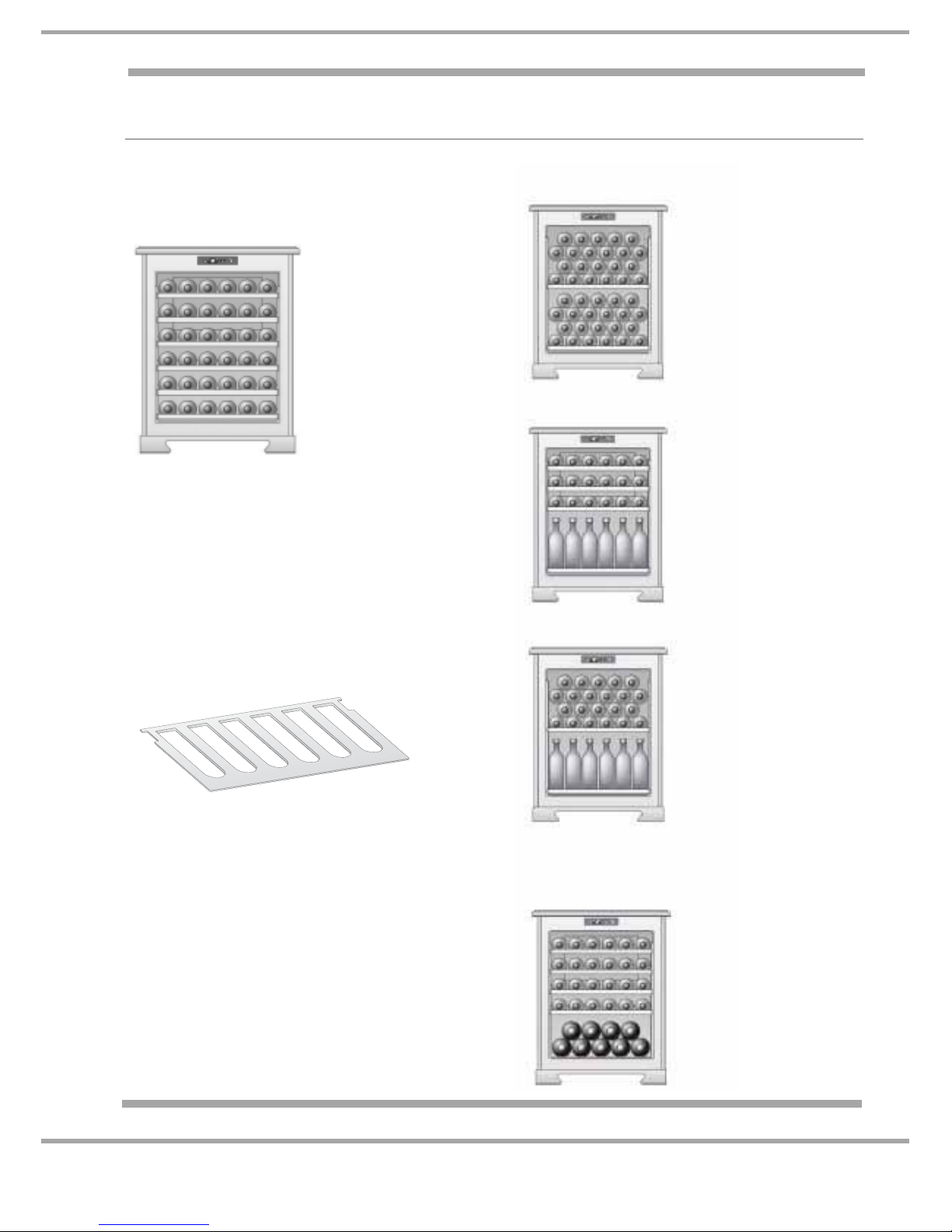
• Bottle storage WL24 of up to 46 bottles - WL36 up to 28 bottles.
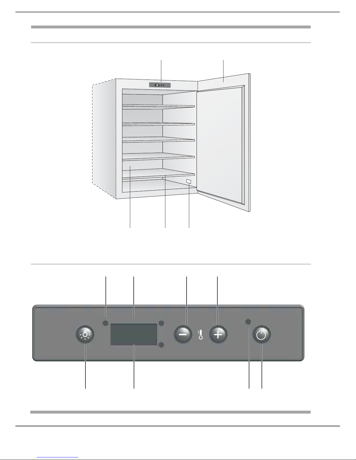
• WL36, 5 wooden support shelves - WL24, 3 wooden support shelves.
• Digital Display - adjustable from +0°C to +18°C.
• Temperature sensing – replaceable thermistor.
• Internal fan to ensure more even temperatures throughout.
• Rear mounted air circulating fan to disperse heat from the condenser.
• Internal fluorescent light.
• Anti-condensation feature - Ventilation fan.
• Internal liner - black - to reduce light transmission / reflection, preserving the wine.
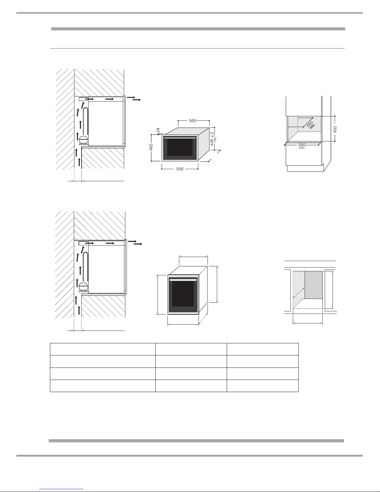
• Can be built-in or built-under a work top.
The main function of the wine cellar is to ensure that the wines are preserved in optimal condition.
When new, the selected temperature was factory pre-set at 15°C, a temperature that is considered
optimal for most wines.
Wine has a complex nature and good wine especially benefits from a long slow process to best
express its attributes, so very specific conditions are necessary.
Most wines being stored can be preserved at the same temperature, but, depending on their
different characteristics, should be served and tasted at very different temperatures.
Just as for wine producers, the actual storage temperature is not the primary concern, rather that the
temperature remains constant through time.
Temperature Display and Manual Adjustment
When the appliance is first plugged in and switched on, the display will indicate the set temperature
(15°C) momentarily. It will then show the internal temperature where there is a variance. This will
gradually change until the set temperature is reached.
• Press the + button on the Control Panel for one second; the display temperature will begin to
flash.
• Press the - or + buttons until the desired temperature is displayed.
• Wait 5 seconds for the display to stop flashing so that the temperature is set.
• Wait until the wine cellar display reaches the set temperature, and then place the bottles as
required.
• The displayed temperature can differ +/- 2°C from the set temperature. This is not critical it is
more important that the interior temperature is constant.
Thermometer Part No. C00149274 (8058) is available as a spare part to monitor temperatures over
time.
Note: User Handbook discrepancy
Models WL24 & WL36 do not have the Ageing Compartment described in some User Instruction
books.

8 of 15
Service Manual UK
Indesit
Company
English
TABLE OF IDEAL WINE TEMPERATURES FOR SERVING
This table indicates the approximate temperatures at which wine should be served. Should one of
your wines need to be served at a temperature that is greater than the temperature inside your wine
cellar, we suggest that you leave it out for the time that is necessary before you serve it.
Amarone della Valpolicella 17°C Dry and Sweet Sparkling Wines 6°C
Barbareso 17°C Verdicchio di Matelica e dei Castelli di Jesi 8°C
Barolo 17°C White Wines from Trentino Alto Adige 11°C
Beaujolais 13°C Franciacorta White Wines 11°C
White liquored Bordeaux 6°C Dry aromatic White Wines 10°C
Dry White Bordeaux 8°C Dry, young and fruity White Wines 8°C
Red Bordeaux 17°C White Wines from Friuli Venezia Giulia 11°C
White Bourgogne 11°C Rodano Wines 15°C
Red Bourgogne 18°C Dry White Wines from the Loire 10°C
Brunello 17°C Liquored Wines from the Loire 7°C
Champagne 6°C Red Wines from the Loire 14°C
Chianti Classico 16°C Liquored Passito Wines 8-18°C
Languedoc-Roussillon 13°C Rosé Wines, New Wines 12°C
Passito di Pantelleria 6°C Light Red Wines with mild tannic 14°C
Rosé Provence 12°C Red, rather tannic Wines with medium
structure 16°C

9 of 15
Indesit Company
Service Manual UK English
STOCKING THE WINE BOTTLES - WL36 illustrated below
For WL26 refer to user handbook
Standard 36-Bottle Stock
The 36-bottle stock (for standard, mixed and
Renana bottles) is recommended for wines
that need to be visible and easily removed.
Position each bottle into the slots on the 5
wooden shelves. 6 bottles can be places on
the bottom of the wine cellar.
The wooden shelves have a special
blocking system so that the bottles do not
accidentally fall and break.
We suggest that the Renana bottles are
placed onto the lower shelf and the bottom of
the wine cellar because they have been
specially designed to hold larger bottles.
The wooden shelf can safely hold up to 22
bottles.
Champagne Bottle Stock
Champagne bottles are larger than standard
bottles. They must be placed onto the base of the
wine cellar, which can hold up to 5.
If you want to stock more than 5 Champagne
bottles in the wine cellar, remove the 5th shelf and
stock the bottles in two rows (placing bottles in the
second row between those on the bottom row).
This will hold up to 9 bottles.
44 Bottles
(100% lying down)
1 shelf
SERVICE
42 Bottles
(50% lying down,
50% standing)
3 shelves
MAXIMUM STOCK
46 Bottles
(48% lying down,
52% standing)
1 shelf
CHAMPAGNE
4 rows
4 rows
}
}
PRESENTATION
Some Stocking Configurations
STANDARD
36 Bottles
(100% lying down)
5 shelves

10 of 15
Service Manual UK
Indesit
Company
English
DISMANTLING PROCEDURE
Important Notes for Guidance:
Before commencing any work refer to the Safety Notes at the beginning of this manual.
A. Remove Wine Cellar from Cabinetry
1. Open the door.
2. Remove 3 screws located in the grey trim at each side, and then close the door.
3. Pull the appliance from the cabinetry a little way, and tape the door closed.
4. Remove the appliance from the cabinetry after disconnection from the electrical supply.
5. Ensure that the door does not support the weight of the appliance if it is removed from the
cabinetry. See Important Notes 1, 2, and 3 overleaf.
B. Top Cover
1. Remove the wine cellar from the cabinetry as in A above.
2. Remove the 4 white plug buttons (2 at each side of the top cover).
3. Use a magnetic screwdriver to locate and remove the screws below.
4. Remove the 2 screws at the rear of the cover.
5. Cut the tape above the ventilator motor and remove the cover.
6. Double sided tape holds the front end of the cover above the display PCB; raising the cover at the
rear will break the bond.
C. Terminal Block
1. Remove the wine cellar from the cabinetry as in A above.
2. Remove the 2 screws securing the terminal block to the cabinet.
3. To open the lid, insert the blade of a small screwdriver under the edge of the lid (left hand side),
raise the screwdriver handle or twist the blade, to open. Press firmly to close.
D. Display Module PCB
1. Remove the top cover as in B above.
2. Remove the tape from each end of the flat metal bracket supporting the PCB and release the
screws.
3. Remove the Rokut rivets securing the PCB.
E. Power Module PCB
1. Remove the top cover as in B above.
2. Remove all connections from the PCB.
3. Remove the 2 screws securing the PCB bracket to the outer cabinet.
4. Depress the 4 plastic post tabs to release the board.
FSensor
1. Remove wooden shelves.
2. Remove the 2 screws from the sensor cover - located internally, on the right hand side at the rear.
3. Remove the 2 screws from the evaporator cover plate.
4. Remove the 4 screws securing the evaporator support brackets to the rear wall.
5. Remove the top cover as in B above.
6. Remove the 2 screws securing the condenser at the right hand side close to the choke / ballast
unit.
continued.....

11 of 15
Indesit Company
Service Manual UK English
G. 12 Volt internal Fan Motor
1. Remove the 2 screws from the evaporator cover plate.
2. Disconnect the fan motor (small male female connector close to the evaporator).
3. Insert the chisel knife between the cover plate and the edge of the fan motor air grille moulding
to ease away from the plate and release the fan motor.
H. Changing the Lamp (Tube)
1. Remove the top two wooden shelves.
2. Remove the Rokut rivets securing the plastic cover over the tube - this can be fiddly, and it is
sometimes better to remove the light assembly.
3. Twist the tube until the pins at the ends are in line vertically, the tube can now be pulled from the
lamp holders at each end.
J. Interior Light Assembly
1. Remove the 6 screws on the outer edge.
2. This will allow the housing to drop, which makes it easier to work on.
3. On reassembly, ensure that the cables are pushed back through the poly-styrene fully before
attempting to refit the light unit.
K. Door Assembly - double glazed
1. Remove the wine cellar from the cabinetry as in A.
2. Remove the top cover as in B.
3. Whilst supporting the door, remove the 4 screws securing the top hinge to the cabinet. Ease the
door and hinge outward; lift the door from the bottom hinge pin.
L. Removing the Wooden Shelves
Follow the instructions below to remove the wooden shelves:
1. Hold the front part of the shelf with one hand.
2. Slowly remove the shelf by pulling it toward you. Pull out the shelf by 1/3 of the way if you need
to remove or replace bottles.
3. Remove or replace the bottles you need and push the shelf back, making sure it locks into place.
4. Make sure the shelf is in place by trying to pull it out once again. If it moves, push it back in again
until it is securely in place.
To completely remove the shelf, follow step 1 and 2 and remove all bottles that on the shelf.
Slowly pull the shelf toward you until you remove it from its slots.
NOTE: - Do not, under any circumstances, remove more than one shelf at a time.
Important Notes:
1. The double glazed door is relatively heavy and some care is required when moving the appliance
or removing the door from the appliance. The door is available as a spare part and is supplied
with the small grey hinge components bolted to the glass.
2. Where the wine cellar has been removed from the cabinetry and is standing on an Oven Standing
Bench or similar surface, the appliance should be placed so that the door over-hangs the bench
tabletop.
3. Where the wine cellar is to be removed from the cabinetry and placed on a floor protector; ensure
that the front end of the cabinet is propped up so that the lower edge of the door is raised from
the floor.

12 of 15
Service Manual UK
Indesit
Company
English
WIRING DIAGRAM
WE26
5407269wd
Black
12 volt Fan Motor
Thermistor
L
L
L
L
N
N
Terminal
Block
Compressor
Blue
Brown
Mauve
Red
White
1
2
Blue
Not Used
Ballast
Choke
Fluorescent Light
White
Orange Yellow Grey
Control
Board
External
Fan
Motor
Transformer Starter
Relay
Switching
Relay
Switching
Relay

13 of 15
Indesit Company
Service Manual UK English
WIRING CONNECTION GUIDE
Fluorescent light
Control
Panel
(viewed from rear)
White
White
White
White
EL CN
Thermistor
Transformer
LINE
IN
Triac
10 Way Ribbon cable to
the display module.
Note: the Black cable in the
ribbon must be on the
Right Hand Side (at each end)
when viewed from the rear
of the appliance.
12-volt
Internal Fan
Motor
Connections

14 of 15
Indesit Company
Service Manual UK English
WIRING CONNECTION TABLES
PCB Connections
Marked
Position
Colour Connected to
Line In Mauve Main Term Block L
Line In Blue Main Term Block N
6 Way block Brown Main Term Block L
6 Way block Red Main Term Block C Unmarked
6 Way block White External Fan Motor
6 Way block Black Main Term Block L
6 Way block Orange Choke / Ballast
Main Terminal Block
Marked
Position
Colour Connected to
LBlack PCB - 6 way Block
LMauve PCB - Line In
LBrown PCB - 6 way Block
NBlue Compressor PTC - N
NBlue Fluorescent Light
NBlue PCB–LineIn
NWhite External Fan Motor
Cunmarked White External Fan Motor
Cunmarked Red PCB - 6 way Block
Cunmarked Brown Compressor PTC - C
Unmarked White PCB - 6 way Block – Unused
Fluorescent Light
Yellow Choke/Ballast Unit
Grey Starter Switch
Blue Terminal Block - N
White Starter Switch
Choke/Ballast Unit
Yellow Fluorescent Light
*Note: the black cable must be on the right hand side on both modules
when viewed from the rear of the appliance.
Orange PCB – 6 way Block
Starter Switch
Grey Fluorescent Light
White Fluorescent Light
Linking Harness – 10 Way
9 Grey + 1 Black*
Power PCB to Display PCB

15 of 15
Indesit Company
Service Manual UK English
This manual suits for next models
3
Table of contents
Other Hotpoint Wine Cooler manuals
Popular Wine Cooler manuals by other brands

Electrolux
Electrolux ERW3313AOX user manual

Vinotemp
Vinotemp WINE-MATE WM-4520SSH Installation, operation & care manual

Caple
Caple WF1549 instruction manual

Sub-Zero
Sub-Zero 315W Specification sheet

AEG
AEG SWB63001DG user manual

Electrolux
Electrolux EI24WC65GS - Wine Cellar With 46 Bottle... Product specifications