8. The letters on the pump stand for:
A = suction connection
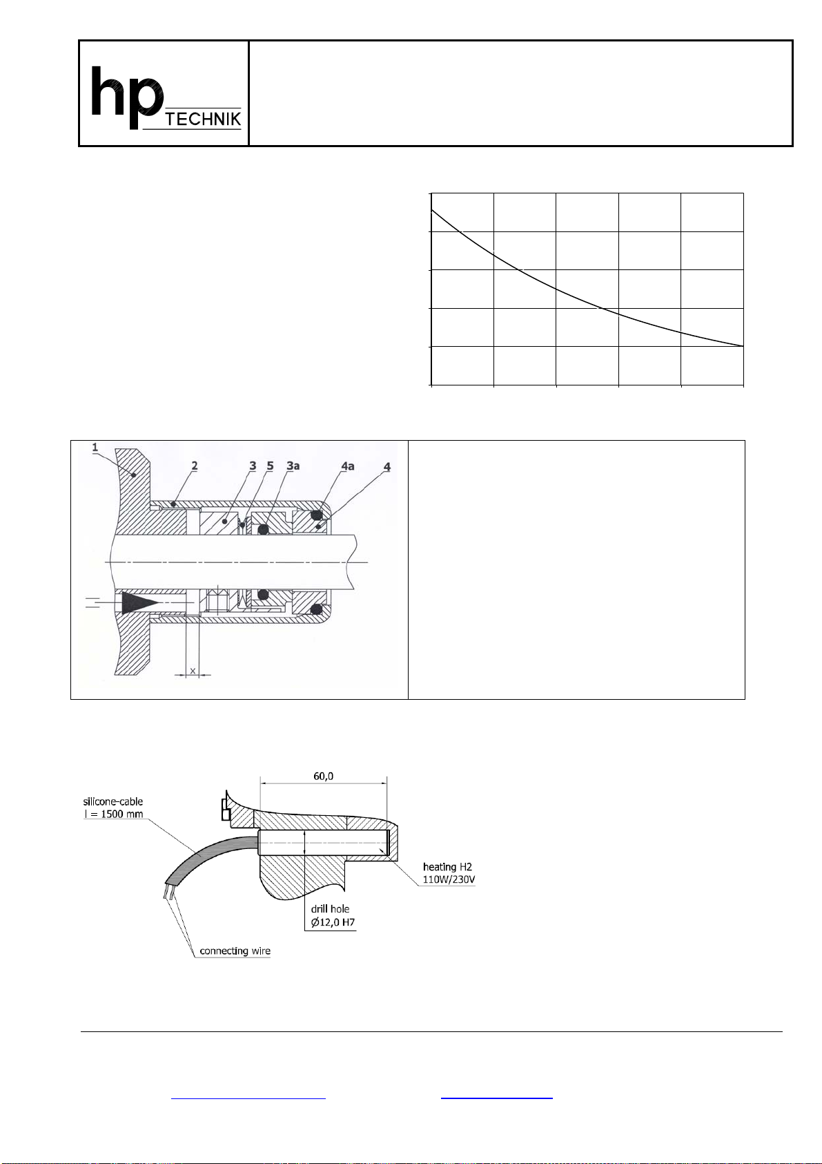
S = nozzle connection
R = return/runback (not separately highlighted)
9. Make sure that the return line leads back to the tank. Any blockage in this line will keep the
pump’s pressure control devices from functioning.
10. Clean all pipes/lines of dirt and/or of metal particles before connecting them to the pump.
11. First fill the pump’s suction connection -A- with oil. Then attach the suction line to the
threaded connection -A-.
12. Connect the nozzle line to - S– and the return line to - R-.
13. Remove the cover screw plug for manometer 1. (Please refer to drawing.)
14. Open all shut-off valves along the lines and on the tank. Check whether there is enough oil
in the tank. Make sure that the pump’s and/or the system’s overflow/pressure relief valve is
completely relaxed as described in points 17, 18 and 19.
Initial Operation
15. Make sure that the pump rotates in the direction of the arrow. Connect the E-motor in
accordance with the electrical data on the plate and switch it on. As a precaution and to
protect the motor, be sure to use a protective motor switch equipped with an overload release!
16. Close the opening for manometer 1 with either the cover screw plug or with the manometer
itself as soon as the oil starts running out of the opening. (Please refer to the drawing.)
17. To put the desired operating pressure remove the covering screw first. (Please refer to the
drawing.)
18. Screw a manometer to the connection for manometer 1 and 2 - providing that this step has
not already been carried out.
19. Use a hexagon key to turn the slotted setting/adjusting cheese head screw which was under the
cover screw on the suction side of the pump.
Turn the setting screw to the right (clockwise) to increase the pressure.
Turn the setting screw to the left (counterclockwise) to decrease the pressure.
When setting the desired operating pressure, assure that a setting is chosen which is
within the permissible pressure range of the built-in pressure spring (a pressure stage
between 1 and 4).
Pressure Range Factory Setting
1: from 1 - 4 bar 2 bar
2: from 2 - 9 bar 6 bar
3: from 6 - 25 bar 15 bar
4: from 15 - 40 bar 15 bar
Attention! Setting a higher operating pressure (one that exceeds the designated pressure
range) will result in the pressure spring blocking and in pressure surges, which,
in turn, will rapidly lead to pump failure.
2/5
hp-TECHNIK GmbH Industriepumpen-Förderaggregate und Anlagenbau
Gablonzer Straße 21 D-76185 Karlsruhe Germany Tel.: 0721/ 9 56 18 - 0
Postfach 21 10 10 D-76160 Karlsruhe Germany FAX: 0721/ 9 56 18 - 28