----
6 – 06/2015
·Before switching on the pump, check that all locking valves in the pipes and check whether the pump has
sufficient medium is available.
·Ensure that the pump is operated in the intended rotational direction (engraved arrow). Connect the
motor according to the information on the type place and switch it on. Preventively provide a motor
protection switch with overload function!
·The presetting of the pump pressure occurs a closed pressure line.
·For pressure regulation, the plug screw (see figure 1) must be removed.
·After removing the cover screw, the pressure regulating screw with hexagon socket (6mm size) is visible.
Use a hexagon wrench to:
- turn it to the right to increase pressure
- turn it to the left to decrease pressure
·When adjusting the desired operational pressure, observe that it may only be set within the permissible
pressure range.
Attention! Setting an operational pressure exceeding the pressure range will cause the spring
to lock and lead to pressure surges and thus to pump outage after a short time.
·When the pressure is set, the pressure adjustment cover screw and its sealing must be replaced oil-tight.
·The pump shaft is sealed to the outside with a mechanical seal made of the materials carbon / SiC and
Viton elastomer.
·The free shaft end has a diameter of 12 mm and is equipped with a groove and spring pursuant to DIN
6885-A-4x4x20.
compliance with the max. pressure range may cause spring
blockage. These in turn causes pressure surges and thus pump
outage after a short time.
If the medium rotates within the pump for too long, this may cause
damage to the valve, overheating and, as a result, mechanical
damage.
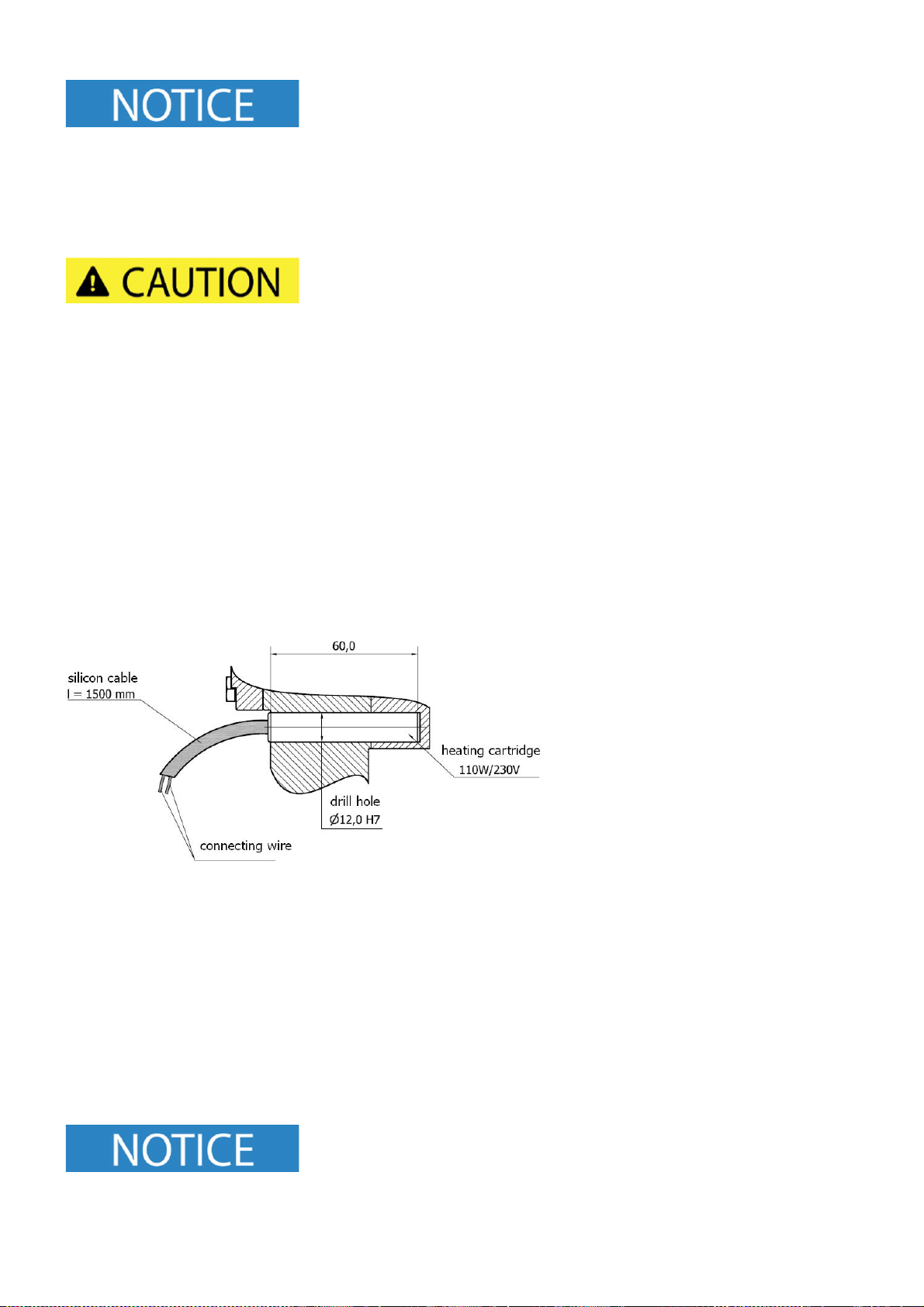
For highly viscous media, a pump heating is prerequisite. To avoid
cavitations and damage to the shaft sealings, the heating times must
be observed under any circumstances.
Because of heat expansion, all valves must be open when heating.
Pumps must never be used as a fix point for the connected pipes. Any forces and moments appearing, e.g.
·Tensions
·Expansion of pipe lines due to temperature influence or reaction forces must be avoided.
·To prevent possible heat expansion of pipe lines, we recommend installing compensators.
·The suction line must be designed so that the flow speed is between 0.5 und max. 1.0 m/sec.
·The pressure line must only reach a maximum of 2 – 2.5 m/sec.
·The suction line must be vacuum-tight and placed in a rising fashion.
·Ensure that the pump and pipe system is not contaminated, e.g. by purging.
·When testing the pipe system for tightness, the max. permissible shaft sealing supply pressure must not
be exceeded.