with an appropriate receptacle.
to connect this plug to
a
standard two contact system.
the adapter
is
used, the ground connection
is
brought out on
a
short wire. This ground lead should then be connected to
a
suitable ground for the protection of operating personnel.
An adapter may be used
When
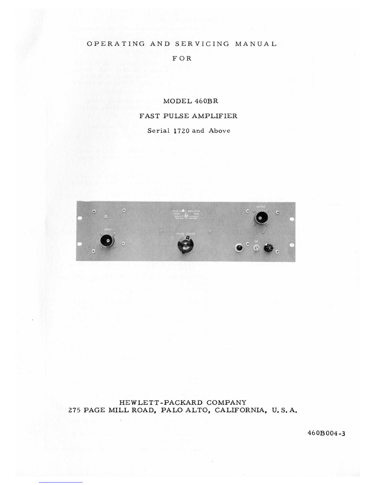
INPUT AND OUTPUT
The input and output jacks on the control panel, require special
200-ohm connectors and cables. (See paragraph
1-2).
2
-4 OPERATION
Connect the Model 460B to the power line, turn on the power
switch and the instrument
is
in operation.
To use
as
a
linear amplifier to amplify sine waves, etc.
,
or
pulses of either polarity, set the LINEAR-PULSE switch to the
LINEAR position.
position the output
is
limited to
16
volts peak into an open circuit
or
8
volts peak into
a
200-ohm load.
a
phase reversal between input and output
is
present and that
a
positive input pulse appears in the output
as
a
negative pulse.
When the LINEAR-PULSE switch
is
in this
It
must be remembered that
To realize the full output capabilities of the Model 46OB, the
LINEAR-PULSE switch must be in the PULSE position and
a
posi-
tive pulse of about
8
volts peak be supplied to the input.
In the PULSE position of the LINEAR-PULSE switch the amplifier
tubes are operated at higher than normal supply voltages.
grid bias
is
increased to keep tube dissipation within ratings.
Under these
conditions
(1-8
volt input) the rated tube dissipation
is
reached with
a
duty cycle of 10%. Lower driving voltages will
allow proportionally higher duty cycles, but the output voltage
will be lower.
The
See Figure
3.
In order to supply this 8-volt positive pulse to
a
Model 460B, the
units may be cascaded or used with one or more Model 46OA
Wide Band Amplifiers, see Figure 4.
In
general, when cascading
460 amplifiers, consideration must be given to the polarity
as
well
as
the amplitude of the pulse to be amplified. For maximum
deflection, the set-up must be arranged so that the input to the
last 460BR amplifier is positive and of approximately 8 volts peak
amplitude. This
is
easily done because the 460BR inverts
the
in-
put pulse. Hence, an additional 460B can be used when necessary
to invert pulse polarity. In most applications an input of about 4
volts
is
sufficient to give satisfactory deflection of
a
cathode-ray
tube. Certain precautions must be taken when cascading several
460
Amplifiers, see Paragraph 2-2, INSTALLATION.
-5-