1-3
Service Information
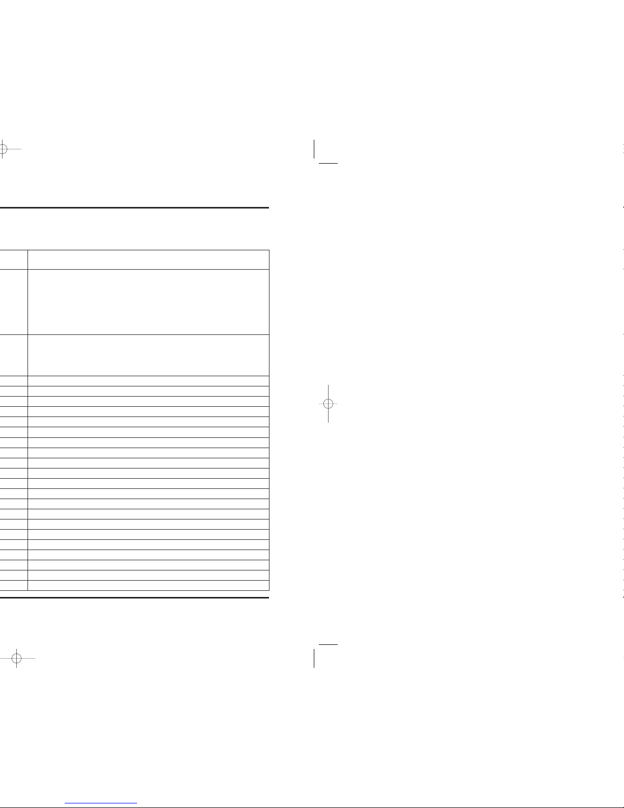
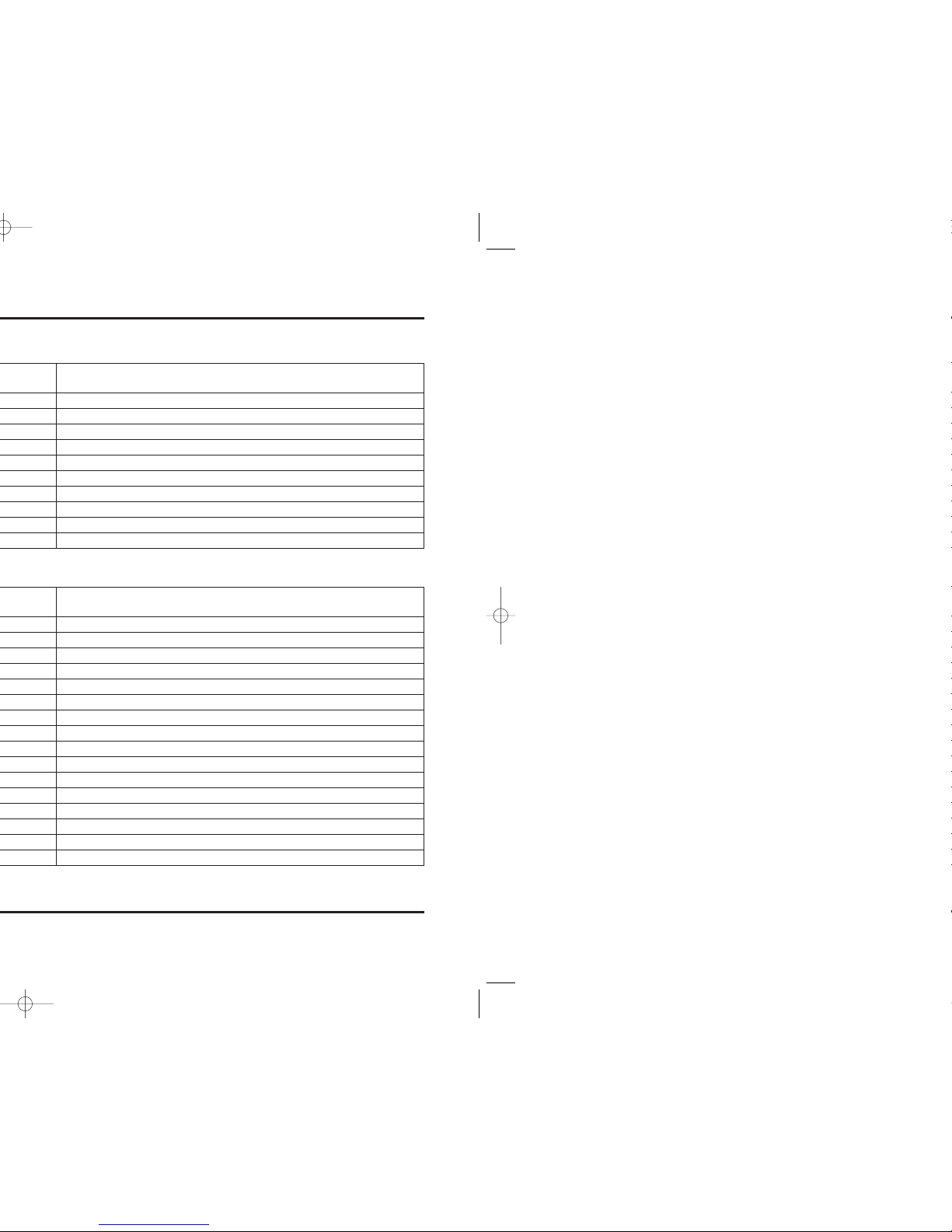
Item Thread/ Torque Remarks
pitch N•m (kgf•m, lbf•ft)
Flywheel bolt Standard M10 x 1.25 103 (10.5, 76) Apply oil; • When using the new crankshaft or flywheel:
Temporarily tighten 2 times with 103 N•m (10.5 kgf•m,
76 lbf•ft).
•Temporarily tighten 1 time when flywheel reinstallation
We recommend that the racing kit flywheel bolt (90003-NL9-000) is
used whenever the standard flwheel is installed (page 2-14).
When using the racing kit flywheel bolt, follow the racing kit
tightening method and torque value (see below).
Racing kit M10 x 1.25 15 (1.5, 11) + 60˚ Apply oil; • Temporarily tighten 3 times with 135 N•m (13.8 kgf•m,
100 lbf•ft).
•After tightening flywheel bolt with 15 N•m (1.5 kgf•m,
11 lbf•ft) + 60˚ , check the tightening torque is more than
128 N•m (13.0 kgf•m, 94 lbf•ft).
Cam sprocket bolt Standard M7 x 1.0 20 (2.0, 14) Apply oil
Racing kit M7 x 1.0 22 (2.2, 16) Apply oil
Camshaft position sensor rotor bolt M6 x 1.0 12 (1.2, 9) Apply oil
Cam chain tensioner bolt M6 x 1.0 9.8 (1.0, 7) Apply LOCKTITE 271
Cam chain guide bolt M6 x 1.0 12 (1.2, 9) Apply LOCKTITE 271
Oil pump assembly bolt M6 x 1.0 12 (1.2, 9) CT bolt
Oil pump driven sprocket bolt M6 x 1.0 15 (1.5, 11) Apply LOCKTITE 271
Oil filter cartridge M20 x 1.5 26 (2.7, 20) Apply oil
Throttle body insulator bolt M6 x 1.0 12 (1.2, 9) Apply oil
Thermostat cover bolt M6 x 1.0 12 (1.2, 9) CT bolt
Water pump cover bolt M6 x 1.0 12 (1.2, 9) CT bolt
Water pump impeller M6 x 1.0 12 (1.2, 9) Left hand thread
Clutch center lock nut M25 x 1.0 128 (13.0, 94) Apply oil
Clutch lifter plate bolt M6 x 1.0 12 (1.2, 9) Apply oil
Transmission bearing set plate bolt M6 x 1.0 14 (1.4, 10) Apply LOCKTITE 271
Lifter plate bolt M6 x 1.0 14 (1.4, 10) Apply oil
Drive sprocket bolt M10 x 1.25 54 (5.5, 40) Wire lock
Shift drum center bolt M8 x 1.25 23 (2.3, 17) Apply LOCKTITE 271
Shift drum stopper arm bolt M6 x 1.0 12 (1.2, 9) Apply oil
Shift return spring pin M8 x 1.25 23 (2.3, 17) Apply oil
Shift drum bearing set plate bolt M6 x 1.0 12 (1.2, 9) Apply LOCKTITE 271
01. Service Information_P1 06.2.20 6:52 PM Page 3