Service Information
1-4
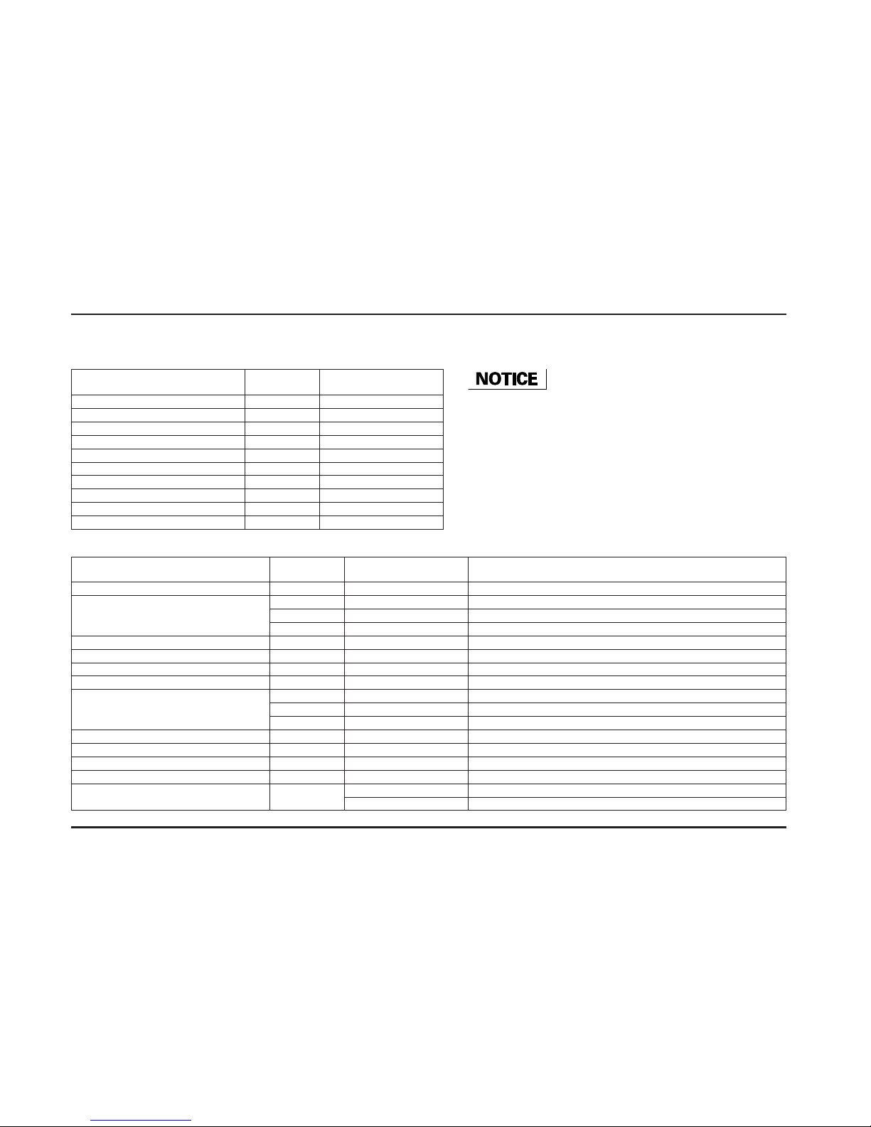
Item Thread/ Torque Remarks
pitch N•m (kgf•m, lbf•ft)
Starter clutch outer special bolt M10 x 1.25 83 (8.5, 61) Apply oil to the threads and seating surface
Flywheel bolt M10 x 1.25 103 (10.5, 76) Apply oil to the threads and seating surface
Cam sprocket knock bolt M7 x 1.0 20 (2.0, 14) Apply locking agent
Cam pulse generator rotor knock bolt M6 x 1.0 12 (1.2, 9) Apply locking agent
Cam chain tensioner A bolt M6 x 1.0 12 (1.2, 9) Apply locking agent
Cam chain tensioner B bolt M10 x 1.25 20 (2.0, 14) Apply locking agent
Cam chain guide bolt/washer M6 x 1.0 12 (1.2, 9)
Oil pump assembly bolt M6 x 1.0 12 (1.2, 9) CT bolt
Oil pump driven sprocket bolt M6 x 1.0 15 (1.5, 11) Apply locking agent
Oil filter cartridge M20 x 1.5 26 (2.7, 20) Apply oil to the threads and seating surface
Spark plug M10 x 1.0 16 (1.6, 12)
Oil filter boss M20 x 1.5 –
See page 1-5, apply locking agent to the threads of the crankcase side
Oil cooler bolt M20 x 1.5 59 (6.0, 43) Apply oil to the threads and seating surface, wire lock
ECT (Tw) sensor M12 x 1.5 23 (2.3, 17)
Primary fuel rail mounting bolt M5 x 1.0 5.1 (0.5, 3.6)
Secondary fuel rail mounting bolt M5 x 1.0 5.3 (0.5, 3.6)
IACV set plate screw M4 x 0.7 2.1 (0.2, 1.4)
Water pump assembly bolt M6 x 1.0 12 (1.2, 9) CT bolt
Thermostat housing cover bolt M6 x 1.0 12 (1.2, 9) CT bolt
Water pump impeller M6 x 1.0 12 (1.2, 9) Left hand thread
Drive sprocket bolt M10 x 1.25 54 (5.5, 40) Wire lock
Throttle body insulator bolt M6 x 1.0 12 (1.2, 9)
Insulator band M5 x 0.8 – See page 1-5
Clutch center lock nut M22 x 1.0 128 (13.1, 95) Apply oil to the threads and seating surface
Clutch spring bolt M6 x 1.0 12 (1.2, 9)
Shift drum center bolt M8 x 1.25 23 (2.3, 17) Apply locking agent
Shift drum stopper arm bolt M6 x 1.0 12 (1.2, 9) Apply locking agent
Shift spindle stopper pin M8 x 1.25 22 (2.2, 16)
Stator mounting socket bolt M6 x 1.0 12 (1.2, 9)
Mainshaft bearing set plate bolt M6 x 1.0 12 (1.2, 9) Apply locking agent
Shift drum bearing set plate bolt M6 x 1.0 12 (1.2, 9) Apply locking agent
Water pump impeller special bolt M6 x 1.0 13 (1.3, 9)
Oil jet pipe mounting bolt M6 x 1.0 12 (1.2, 9) Apply locking agent